EP0979765A2 - Method for transmitting the counting value from a counting point to a central evaluation device - Google Patents
Method for transmitting the counting value from a counting point to a central evaluation device Download PDFInfo
- Publication number
- EP0979765A2 EP0979765A2 EP99440222A EP99440222A EP0979765A2 EP 0979765 A2 EP0979765 A2 EP 0979765A2 EP 99440222 A EP99440222 A EP 99440222A EP 99440222 A EP99440222 A EP 99440222A EP 0979765 A2 EP0979765 A2 EP 0979765A2
- Authority
- EP
- European Patent Office
- Prior art keywords
- evaluation device
- central evaluation
- metering
- point
- communication network
- Prior art date
- Legal status (The legal status is an assumption and is not a legal conclusion. Google has not performed a legal analysis and makes no representation as to the accuracy of the status listed.)
- Granted
Links
Images
Classifications
-
- B—PERFORMING OPERATIONS; TRANSPORTING
- B61—RAILWAYS
- B61L—GUIDING RAILWAY TRAFFIC; ENSURING THE SAFETY OF RAILWAY TRAFFIC
- B61L1/00—Devices along the route controlled by interaction with the vehicle or vehicle train, e.g. pedals
- B61L1/16—Devices for counting axles; Devices for counting vehicles
- B61L1/168—Specific transmission details
-
- B—PERFORMING OPERATIONS; TRANSPORTING
- B61—RAILWAYS
- B61L—GUIDING RAILWAY TRAFFIC; ENSURING THE SAFETY OF RAILWAY TRAFFIC
- B61L1/00—Devices along the route controlled by interaction with the vehicle or vehicle train, e.g. pedals
- B61L1/16—Devices for counting axles; Devices for counting vehicles
- B61L1/161—Devices for counting axles; Devices for counting vehicles characterised by the counting methods
-
- B—PERFORMING OPERATIONS; TRANSPORTING
- B61—RAILWAYS
- B61L—GUIDING RAILWAY TRAFFIC; ENSURING THE SAFETY OF RAILWAY TRAFFIC
- B61L27/00—Central railway traffic control systems; Trackside control; Communication systems specially adapted therefor
- B61L27/20—Trackside control of safe travel of vehicle or vehicle train, e.g. braking curve calculation
-
- B—PERFORMING OPERATIONS; TRANSPORTING
- B61—RAILWAYS
- B61L—GUIDING RAILWAY TRAFFIC; ENSURING THE SAFETY OF RAILWAY TRAFFIC
- B61L2205/00—Communication or navigation systems for railway traffic
- B61L2205/02—Global system for mobile communication - railways (GSM-R)
Definitions
- the invention relates to a method for transmitting one from a metering point determined meter reading to a central evaluation device, the free or busy messages generated for a route section.
- the invention further relates to a Procedure for free notification of a route section and an electronic connection box for a point of delivery.
- Axle counters are used in rail traffic in particular in connection with track vacancy detection systems.
- Modern axle counters such as B. from an article by G. Poppe with the title field of application of the new microcomputer metering point Zp30C, ETR, 41 (1992), H. 7-8, pages 519 - 522, are known, consist of several metering points arranged along the route and a central evaluation device usually housed in a signal box.
- Each metering point comprises two rail contacts and a control circuit, which is referred to as an electronic junction box (EAK).
- EAK electronic junction box
- the metering points transmit their meter readings to the central evaluation device upon request.
- the evaluation device compares the incoming meter readings with one another, corrects them if necessary, and generates free or busy messages.
- the metering points do not transmit meter readings to the evaluation device, but rather in real time the output signals generated by the rail contact (possibly amplified). Only the central evaluation device generates counting pulses and counter readings from it.
- a railroad safety system is also known in which decentralized safety devices, to which one or more track elements are connected, communicate with locomotives in an event-oriented manner via public mobile radio networks.
- This known system is particularly suitable for regional trains and enables operation in which the locomotives request status reports by radio even with decentralized route protection devices (switches, track vacancy detection devices, etc.) affected by the intended journey.
- the status reports received in the locomotive are compared with reference data stored there. The driver is only shown a driver's license if there is a match.
- Central line security devices (signal boxes) are not required in this known system.
- the object of the invention is to provide a method for the transmission of a point of delivery to determine determined meter reading to a central evaluation device.
- the method should be particularly suitable for low-traffic secondary routes and neither high costs for the railway operator in terms of acquisition while still in operation cause.
- the meter reading is transmitted to the central evaluation device via a communication network which is switched is based.
- This communication network can be, for example public landline or a mobile network. Which network in individual cases to be preferred will depend on local conditions. Exists in the in the immediate vicinity of the point of delivery a connection to a public Landline, so it will. U. mainly for reasons of reliability and cost be the cheapest to connect the point of delivery to this landline. Often, however the metering points are far from public landlines. In these cases communication over a public cellular network may be preferable. Conceivable is also, communication lines of the track operator laid along the rail routes - often implemented as glass fibers - for this communication.
- the central one Evaluation device for example, in a signal box or in an operations control center located, relates the counter readings to one another and generates them Free or busy messages. If necessary, takes place in the central evaluation device an error correction also takes place. The free and busy messages generated are then displayed or processed in an interlocking logic. Since communication with the central evaluation device via radio or existing communication networks takes place, there is no effort for that Laying and maintenance of dedicated lines to be set up for this purpose. This is one of the main advantages of the solution according to the invention.
- Messages from the central evaluation device to the point of delivery are also sent transmitted via the communication network based on switching.
- everyone Metering point which should be addressable, has an address, which is basically is nothing more than a normal phone number. Security requirements can be matched by suitable coding of the data to be transmitted.
- the inventive method Procedure u. U. not as high train density as possible with the known communication via permanently available dedicated lines. Therefore, this method is particularly suitable for use on vehicles with less traffic Branch lines on. Since the profitability of such routes largely depends on the investments and operating expenses required for railway signaling depends, the invention can contribute to many previously unprofitable routes can be operated again profitably.
- the communication to the central evaluation device done via mobile radio it can be particularly useful for remote metering points be a local power supply, such as a battery or solar panel. Then neither communication nor power supply cables are required to be relocated.
- the central evaluation device AWE communicates with metering points ZP1 ... ZP3, whereby communication connections are only established if necessary.
- this communication link includes transmission paths a public telephone network PSTN.
- the metering points and the central Evaluation device AWE are here with conventional telephone connections equipped that allow a connection to be established if required.
- the operator of the railways can of course also use a telephone network non-public or a telephone or data network maintained by himself use. In general, any communication network comes into question here, which one guarantees a need-based connection establishment based on mediation. In this way, the cabling effort compared to solutions is fixed switched point-to-point connections significantly reduced.
- the communication connection is between the metering points ZP1 ... ZP3 and the central evaluation device AR a radio connection. It is essential here that there is no communication own, constantly available radio channel is reserved, but that, as in the above shown wired case, a channel is assigned only when needed. In An area with a large number of field elements can thus have one or a few Channels all communications are handled because of the existing Bandwidth scarcity brings significant cost advantages. Especially in Areas of low traffic routes are those due to the establishment of a connection or the channel assignment due to time delays acceptable.
- the radio connection is preferably a mobile radio connection.
- the electronic connection boxes of metering points ZP1 ... ZP3 are in this Case integrated mobile devices that dial into a public mobile network allow.
- the data arrive at a base station via the radio interface BTS and from there to a mobile switching center MSC, which sends the data to a line Network PSTN relayed.
- the central evaluation device AWE is directly connected to the PSTN network.
- the communication link in this case includes both transmission paths of a wired and also of a radio-based communication network.
- By including one (Mobile) radio connection is - apart from the connection of the electronic junction boxes with the rail contacts - no wiring required.
- a metering point only then in the Communication network dials in if after the last registered axis pass a specified period of time has passed. This means a departure from the process, as it is hard-wired from known, with a central evaluation device Meter points knows. Meter readings are transmitted there on request through the evaluation device. In contrast, in the method according to the invention communication takes place only after the end of a train journey. So that will achieves that the central evaluation device on the one hand immediately on every traffic event informs, but only a communication link for the period of time that is absolutely necessary for the transmission of the counting result is.
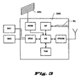
- Fig. 3 shows an embodiment of an electronic connection box EAK according to the invention in a schematic representation.
- the electronic junction box EAK is connected to rail contacts SK1 and SK2 via an interface IFSK.
- the signals picked up by the receiver coils of the rail contacts are fed to an evaluation circuit AS via this interface IFSK.
- the evaluation circuit AS has the task of driving the two rail contacts SK1 and SK2, generating counting pulses from the signals supplied via the rail contact interface IFSK and determining a counter reading therefrom.
- G. Hoffmann and H. Uebel with the title "New metering points (Zp 30) for axle counters", Signal + Draht 77 (1985) 4, pages 72-77.
- a second interface IFGSM provides the connection to the communication network
- the communication network is a public mobile radio network according to the GSM standard.
- the interface is therefore known as such GSM transceiver part executed.
- the communication network is a landline, for example, the IFGSM interface can be a simple X.25 interface, as is often the case in public data networks for packet-switched data communication used.
- the evaluation circuit AS is connected to a timer circuit TIM.
- This Timer circuit TIM is designed so that when one of the evaluation circuit is received AS supplied counting pulse a timer is started. The timer runs as long until the next count pulse is received and the timer is reset. Exceeds the timer has a predetermined value, e.g. B. 15 seconds, it is assumed that the end of the rail vehicle or the train set the rail contacts happened. The timer then issues a send command to cause that the determined meter reading is transmitted to the central evaluation device becomes.
- the time period after its elapse a send command is issued, not fixed once, but instead from the timer circuit after evaluating the chronological sequence of the previously received Count pulses set.
- the reasoning behind it is that it depends on the speed of the passing rail vehicle depends on when you fail to arrive of counting pulses with a very high probability can assume that no axes pass the rail contacts. For example, at the counting impulses for a fast moving train association at short intervals on each other. The timer circuit evaluates these time intervals and, for example, provides determined that the longest occurring interval does not exceed 1 second. From this size, the time period is then calculated, after which a Send command is issued. For example, the calculation can be done in a simple Multiplication by a fixed value, such as 5, exist. This means five seconds the send command is issued after the last registered axis pass becomes. With a slow train, on the other hand, with a train between two axles can pass several seconds, the calculated value will be correspondingly higher lie.
- the electronic junction box EAK relates to an advantageous embodiment the electrical energy required from a local power supply.
- this is designed as a rechargeable battery ACCU.
- a solar panel SOL is provided for loading the rechargeable battery.
- the electronic junction box EAK has a memory SP with input means KL. Your own address and address are stored in this memory can be stored in the central evaluation device.
- the addresses can be, for example are normal phone numbers.
- the input means KL can be used as Wire jumpers or, as indicated in Fig. 3, be designed as a card reader. With A card reader can be particularly easily integrated into the electronic Junction box EAK addresses entered. Such card readers are preferred also available in the central evaluation facilities to find the addresses of the to enter metering points arranged along the rail route. On the cards codes can also be stored, with the aid of which the data transmission can also be carried out can be backed up to any existing data backup measures.
- the central evaluation device in addition in regular time intervals establishes a connection to the metering points and meter readings queries. If the metering points are equipped with means for carrying out self-tests , they are preferably used as part of the regular meter reading queries initiated and their result transmitted to the evaluation device. In this way, defects in metering points can be made within the required disclosure period identify.
Abstract
Description
Die Erfindung betrifft ein Verfahren zur Übermittlung eines von einem Zählpunkt ermittelten Zählerstands an eine zentrale Auswerteeinrichtung, die Frei- oder Besetztmeldungen für einen Streckenabschnitt erzeugt. Die Erfindung betrifft ferner ein Verfahren zur Freimeldung eines Streckenabschnitts sowie einen elektronischen Anschlußkasten für einen Zählpunkt.The invention relates to a method for transmitting one from a metering point determined meter reading to a central evaluation device, the free or busy messages generated for a route section. The invention further relates to a Procedure for free notification of a route section and an electronic connection box for a point of delivery.
Im Schienenverkehr werden insbesondere im Zusammenhang mit Gleisfreimeldeeinrichtungen Achszähler eingesetzt. Moderne Achszähler, wie sie z. B. aus einem Aufsatz von G. Poppe mit dem Titel Einsatzbereich des neuen Mikrorechner-Zählpunktes Zp30C, ETR, 41 (1992), H. 7-8, Seiten 519 - 522, bekannt sind, bestehen aus mehreren entlang der Strecke angeordneten Zählpunkten und einer üblicherweise in einem Stellwerk untergebrachten zentralen Auswerteeinrichtung. Jeder Zählpunkt umfaßt zwei Schienenkontakte sowie eine Ansteuerschaltung, die man als Elektronischen Anschlußkasten (EAK) bezeichnet. Die Zählpunkte übermitteln der zentralen Auswerteeinrichtung auf deren Anforderung hin ihre Zählerstände. Die Auswerteeinrichtung vergleicht die eingehenden Zählerstände miteinander, korrigiert sie gegenbenenfalls und generiert Frei- oder Besetztmeldungen. Bei einfacher ausgeführten Achszählern übermitteln die Zählpunkte an die Auswerteeinrichtung keine Zählerstände, sondern in Echtzeit die vom Schienenkontakt erzeugten Ausgangssignale (ggf. verstärkt). Erst die zentrale Auswerteeinrichtung erzeugt daraus Zählimpulse und Zählerstände. Axle counters are used in rail traffic in particular in connection with track vacancy detection systems. Modern axle counters, such as B. from an article by G. Poppe with the title field of application of the new microcomputer metering point Zp30C, ETR, 41 (1992), H. 7-8, pages 519 - 522, are known, consist of several metering points arranged along the route and a central evaluation device usually housed in a signal box. Each metering point comprises two rail contacts and a control circuit, which is referred to as an electronic junction box (EAK). The metering points transmit their meter readings to the central evaluation device upon request. The evaluation device compares the incoming meter readings with one another, corrects them if necessary, and generates free or busy messages. In the case of simple axle counters, the metering points do not transmit meter readings to the evaluation device, but rather in real time the output signals generated by the rail contact (possibly amplified). Only the central evaluation device generates counting pulses and counter readings from it.
Aus einem Aufsatz von H. Materne und A. Baer mit dem Titel Funkgestützte integrale Leit-, Informations- und Sicherungstechnik für Regionalbahnen, ZEV + DET Glas. Ann. 120 (1996) Nr. 11/12, Seiten 461 - 467, ist ferner ein Eisenbahnsicherungssystem bekannt, bei dem dezentrale Sicherungseinrichtungen, an die ein oder mehrere Fahrwegelemente angeschlossen sind, ereignisorientiert über öffentliche Mobilfunknetze mit Triebfahrzeugen kommunizieren. Dieses bekannte System ist besonders für Regionalbahnen geeignet und ermöglicht einen Betrieb, bei dem die Triebfahrzeuge selbst bei von der vorgesehenen Fahrt betroffenen dezentralen Streckensicherungseinrichtungen (Weichen, Gleisfreimeldeeinrichtungen etc.) Zustandsmeldungen über Funk anfordern. Die im Triebfahrzeug eingegangenen Zustandsmeldungen werden mit dort abgelegten Referenzdaten verglichen. Nur wenn eine Übereinstimmung vorliegt, wird dem Triebfahrzeugführer eine Fahrerlaubnis angezeigt. Zentrale Strekkensicherungseinrichtungen (Stellwerke) sind bei diesem bekannten System nicht erforderlich.From an essay by H. Materne and A. Baer entitled Radio-based integral control, information and security technology for regional railways, ZEV + DET glass. Ann. 120 (1996) No. 11/12, pages 461-467, a railroad safety system is also known in which decentralized safety devices, to which one or more track elements are connected, communicate with locomotives in an event-oriented manner via public mobile radio networks. This known system is particularly suitable for regional trains and enables operation in which the locomotives request status reports by radio even with decentralized route protection devices (switches, track vacancy detection devices, etc.) affected by the intended journey. The status reports received in the locomotive are compared with reference data stored there. The driver is only shown a driver's license if there is a match. Central line security devices (signal boxes) are not required in this known system.
Aufgabe der Erfindung ist es, ein Verfahren zur Übermittlung des von einem Zählpunkt ermittelten Zählerstands an eine zentrale Auswerteeinrichtung anzugeben. Das Verfahren soll besonders für verkehrsärmere Nebenstrecken geeignet sein und weder in der Anschaffung noch im laufenden Betrieb hohe Kosten für den Bahnbetreiber verursachen.The object of the invention is to provide a method for the transmission of a point of delivery to determine determined meter reading to a central evaluation device. The The method should be particularly suitable for low-traffic secondary routes and neither high costs for the railway operator in terms of acquisition while still in operation cause.
Diese Aufgabe wird von der Erfindung gelöst, die die in Anspruch 1 aufgeführten Merkmale hat. Erfindungsgemäß erfolgt die Übermittlung des Zählerstands an die zentralen Auswerteeinrichtung über ein Kommunikationsnetz, welches auf Vermittlung beruht. Bei diesem Kommunikationsnetz kann es sich beispielsweise um ein öffentliches Festnetz oder um ein Mobilfunknetz handeln. Welches Netz im Einzelfall vorzuziehen ist, wird von den örtlichen Gegebenheiten abhängen. Besteht in der unmittelbaren Nähe des Zählpunktes eine Anschlußmöglichkeit an ein öffentliches Festnetz, so wird es u. U. vor allem aus Gründen der Zuverlässig und der Kosten am günstigsten sein, den Zählpunkt an dieses Festnetz anzuschließen. Häufig jedoch befinden sich die Zählpunkte weitab von öffentlichen Festnetzen. In diesen Fällen wird eine Kommunikation über ein öffentliches Mobilfunknetz vorzuziehen sein. Denkbar ist auch, entlang der Schienenstrecken verlegte Kommunikationsleitungen des Fahrwegbetreibers - häufig als Glasfasern ausgeführt - für diese Kommunikation zu nutzen.This object is achieved by the invention, which are listed in claim 1 Has characteristics. According to the invention, the meter reading is transmitted to the central evaluation device via a communication network which is switched is based. This communication network can be, for example public landline or a mobile network. Which network in individual cases to be preferred will depend on local conditions. Exists in the in the immediate vicinity of the point of delivery a connection to a public Landline, so it will. U. mainly for reasons of reliability and cost be the cheapest to connect the point of delivery to this landline. Often, however the metering points are far from public landlines. In these cases communication over a public cellular network may be preferable. Conceivable is also, communication lines of the track operator laid along the rail routes - often implemented as glass fibers - for this communication.
Allen Varianten ist gemeinsam, daß keine Zählimpulse, sondern ein Zählerstand vom Zählpunkt direkt zur zentralen Auswerteeinrichtung übertragen wird. Die zentrale Auswerteeinrichtung, die sich beispielsweise in einem Stellwerk oder in einer Betriebsleitstelle befindet, setzt die Zählerstände miteinander in Beziehung und erzeugt Frei- oder Besetztmeldungen. Gegebenenfalls findet in der zentralen Auswerteeinrichtung auch eine Fehlerkorrektur statt. Die erzeugten Frei- und Besetztmeldungen werden anschließend zur Anzeige gebracht oder in einer Stellwerkslogik weiterverarbeitet. Da die Kommunikation mit der zentralen Auswerteeinrichtung über Funk oder bereits vorhandene Kommunikationsnetze erfolgt, entsteht kein Aufwand für das Verlegen und die Unterhaltung von eigens zu diesem Zweck einzurichtenden Standleitungen. Hierin besteht einer der wesentlichen Vorteile der erfindungsgemäßen Lösung.All variants have in common that no counts, but a counter reading from Point of delivery is transferred directly to the central evaluation device. The central one Evaluation device, for example, in a signal box or in an operations control center located, relates the counter readings to one another and generates them Free or busy messages. If necessary, takes place in the central evaluation device an error correction also takes place. The free and busy messages generated are then displayed or processed in an interlocking logic. Since communication with the central evaluation device via radio or existing communication networks takes place, there is no effort for that Laying and maintenance of dedicated lines to be set up for this purpose. This is one of the main advantages of the solution according to the invention.
Für die Nutzung des Kommunikationsnetzes entstehen aber dennoch Kosten, deren Höhe üblicherweise von der Dauer der aufgebauten Verbindung abhängen. Um auch diese laufenden Kosten möglichst gering zu halten, ist außerdem vorgesehen, daß ein Zählpunkt sich erst dann in das Kommunikationsnetz einwählt, wenn nach dem letzten registrierten Achsdurchgang eine festgelegte Zeitspanne verstrichen ist. Dadurch wird erreicht, daß eine Verbindung nur nach Abschluß einer Zugfahrt durch den Zählpunkt aufgebaut wird.However, there are costs for the use of the communication network The height usually depends on the duration of the connection. Too To keep these running costs as low as possible, it is also envisaged that a Metering point only dials into the communication network if after the last one a defined period of time has elapsed. Thereby is achieved that a connection only after completion of a train journey through the Point of delivery is established.
Mitteilungen von der zentralen Auswerteeinrichtung an den Zählpunkt werden ebenfalls über das auf Vermittlung beruhende Kommunikationsnetz übertragen. Jeder Zählpunkt, welcher ansprechbar sein soll, hat dazu eine Adresse, die grundsätzlich nichts anderes als eine normale Telefonnummer ist. Sicherheitsanforderungen kann durch eine geeignete Codierung der zu übertragenden Daten entsprochen werden. Messages from the central evaluation device to the point of delivery are also sent transmitted via the communication network based on switching. Everyone Metering point, which should be addressable, has an address, which is basically is nothing more than a normal phone number. Security requirements can be matched by suitable coding of the data to be transmitted.
Da der Aufbau der Kommunikationsverbindung Zeit benötigt, sind bei dem erfindungsgemäßen Verfahren u. U. keine so hohen Zugfolgedichten möglich wie bei der bekannten Kommunikation über dauerhaft zur Verfügung stehende Standleitungen. Daher bietet sich dieses Verfahren besonders für den Einsatz auf schwächer befahrenen Nebenstrecken an. Da die Rentabilität solcher Strecken im hohen Maße von den für die Eisenbahnsignaltechnik erforderlichen Investitionen und Betriebsausgaben abhängt, kann die Erfindung dazu beitragen, daß viele bislang unrentable Strecken wieder gewinnbringend betrieben werden können.Since it takes time to set up the communication connection, the inventive method Procedure u. U. not as high train density as possible with the known communication via permanently available dedicated lines. Therefore, this method is particularly suitable for use on vehicles with less traffic Branch lines on. Since the profitability of such routes largely depends on the investments and operating expenses required for railway signaling depends, the invention can contribute to many previously unprofitable routes can be operated again profitably.
Wenn, wie oben angeführt, die Kommunikation zur zentralen Auswerteeinrichtung über Mobilfunk erfolgt, so kann es insbesondere bei abgelegenen Zählpunkten sinnvoll sein, eine lokale Stromversorgung, etwa eine Batterie oder ein Solarpanel, vorzusehen. Es brauchen dann weder Kommunikations- noch Stromversorgungskabel verlegt zu werden.If, as mentioned above, the communication to the central evaluation device done via mobile radio, it can be particularly useful for remote metering points be a local power supply, such as a battery or solar panel. Then neither communication nor power supply cables are required to be relocated.
Die Erfindung wird nachfolgend anhand der Ausführungsbeispiele und der Zeichnungen eingehend erläutert. Es zeigen:
- Fig. 1:
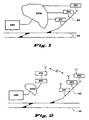
- Schematische Darstellung zur Erläuterung eines Ausführungsbeispiels der Erfindung, bei der Zählpunkte ZP1...ZP3 über ein öffentliches Telefonnetz PSTN mit einer zentralen Auswerteeinrichtung AWE kommuniziert;
- Fig. 2:
- Schematische Darstellung zur Erläuterung eines anderen Ausführungsbeispiels der Erfindung, bei der Zählpunkte ZP1...ZP3 über ein Mobilfunknetz mit einer zentralen Auswerteeinrichtung AWE kommuniziert;
- Fig. 3:
- Darstellung eines elektronischen Anschlußkastens nach Anspruch 4. Bei dem in Fig. 1 gezeigten Ausschnitt aus einem Schienennetz zweigt eine Nebenstrecke NS von einer Hauptstrecke HS ab. Entlang der Nebenstrecke NS sind Zählpunkte ZP1...ZP3 angeordnete. Die sicherheitstechnische Überwachung und Steuerung des gezeigten Streckenbereichs findet in einer zentralen Auswerteeinrichtung AWE statt. Diese kann beispielsweise in einem (Block)Stellwerk untergebracht sein.
- Fig. 1:
- Schematic representation to explain an embodiment of the invention, in which metering points ZP1 ... ZP3 communicate with a central evaluation device AWE via a public telephone network PSTN;
- Fig. 2:
- Schematic representation for explaining another embodiment of the invention, in which metering points ZP1 ... ZP3 communicate with a central evaluation device AWE via a mobile radio network;
- Fig. 3:
- Representation of an electronic junction box according to claim 4. In the section of a rail network shown in FIG. 1, a branch line NS branches off from a main line HS. Metering points ZP1 ... ZP3 are arranged along the branch line NS. The safety-related monitoring and control of the route area shown takes place in a central evaluation device AWE. This can, for example, be accommodated in a (block) signal box.
Die zentrale Auswerteeinrichtung AWE kommuniziert mit Zählpunkten ZP1...ZP3, wobei Kommunikationsverbindungen nur bei Bedarf aufgebaut werden. Bei dem in Fig. 1 dargestellten Beispiel umfaßt diese Kommunikationsverbindung Übertragungswege eines öffentlichen Telefonnetzes PSTN. Die Zählpunkte und die zentrale Auswerteeinrichtung AWE sind also hier mit herkömmlichen Telefonanschlüssen ausgestattet, die einen Verbindungsaufbau bei Bedarf ermöglichen. Anstelle des öffentlichen Telefonnetzes kann der Betreiber der Schienenwege natürlich auch ein nicht öffentliches oder ein von ihm selbst unterhaltenes Telefon- oder Datennetz verwenden. Ganz allgemein kommt hier jedes Kommunikationsnetz in Frage, welches einen bedarfsweisen, auf Vermittlung beruhenden Verbindungsaufbau gewährleistet. Auf diese Weise ist der Verkabelungsaufwand gegenüber Lösungen mit fest geschalteten Punkt-zu-Punkt-Verbindungen erheblich vermindert.The central evaluation device AWE communicates with metering points ZP1 ... ZP3, whereby communication connections are only established if necessary. At the in 1 illustrated example, this communication link includes transmission paths a public telephone network PSTN. The metering points and the central Evaluation device AWE are here with conventional telephone connections equipped that allow a connection to be established if required. Instead of the public The operator of the railways can of course also use a telephone network non-public or a telephone or data network maintained by himself use. In general, any communication network comes into question here, which one guarantees a need-based connection establishment based on mediation. In this way, the cabling effort compared to solutions is fixed switched point-to-point connections significantly reduced.
Bei dem in Fig. 2 dargestellten Ausführungsbeispiel ist die Kommunikationsverbindung zwischen den Zählpunkten ZP1...ZP3 und der zentralen Auswerteeinrichtung AWE eine Funkverbindung. Wesentlich ist hier, daß für die Kommunikation kein eigener, ständig verfügbarer Funkkanal reserviert ist, sondern daß, wie auch im oben dargestellten leitungsgebundenen Fall, ein Kanal nur bei Bedarf zugewiesen wird. In einem Gebiet mit einer Vielzahl von Feldelementen können so über einen oder wenige Kanäle die gesamte Kommunikation abgewickelt werden, was wegen der bestehenden Bandbreiteknappheit deutliche Kostenvorteile mit sich bringt. Vor allem im Bereich von schwach befahrenen Strecken sind die durch den Verbindungsaufbau bzw. die Kanalzuweisung bedingten Zeitverzögerungen hinnehmbar.In the exemplary embodiment shown in FIG. 2, the communication connection is between the metering points ZP1 ... ZP3 and the central evaluation device AR a radio connection. It is essential here that there is no communication own, constantly available radio channel is reserved, but that, as in the above shown wired case, a channel is assigned only when needed. In An area with a large number of field elements can thus have one or a few Channels all communications are handled because of the existing Bandwidth scarcity brings significant cost advantages. Especially in Areas of low traffic routes are those due to the establishment of a connection or the channel assignment due to time delays acceptable.
Vorzugsweise handelt es sich bei der Funkverbindung um eine Mobilfunkverbindung. In den elektronischen Anschlußkästen der Zählpunkte ZP1...ZP3 sind in diesem Fall Mobilfunkgeräte integriert, die ein Einwählen in ein öffentliches Mobilfunknetz gestatten. Über die Funkschnittstelle gelangen die Daten zu einer Basisstation BTS und von dort zu einer Mobilvermittlungsstelle MSC, die die Daten an ein leitungsgebundenes Netz PSTN weitervermittelt. Die zentrale Auswerteeinrichtung AWE ist unmittelbar an das Netz PSTN angebunden. Die Kommunikationsverbindung umfaßt in diesem Fall sowohl Übertragungswege eines leitungsgebundenen als auch eines funkgestützten Kommunikationsnetzes. Durch die Einbeziehung einer (Mobil-)Funkverbindung ist - abgesehen von der Verbindung der elektronischen Anschlußkästen mit den Schienenkontakten - keinerlei Verkabelung erforderlich.The radio connection is preferably a mobile radio connection. In the electronic connection boxes of metering points ZP1 ... ZP3 are in this Case integrated mobile devices that dial into a public mobile network allow. The data arrive at a base station via the radio interface BTS and from there to a mobile switching center MSC, which sends the data to a line Network PSTN relayed. The central evaluation device AWE is directly connected to the PSTN network. The communication link in this case includes both transmission paths of a wired and also of a radio-based communication network. By including one (Mobile) radio connection is - apart from the connection of the electronic junction boxes with the rail contacts - no wiring required.
Erfindungsgemäß ist außerdem vorgesehen, daß ein Zählpunkt sich erst dann in das Kommunikationsnetz einwählt, wenn nach dem letzten registrierten Achsdurchgang eine festgelegte Zeitspanne verstrichen ist. Dies bedeutet eine Abkehr vom Ablauf, wie man ihn von bekannten, mit einer zentrale Auswerteeinrichtung fest verdrahteten Zählpunkten kennt. Dort erfolgt die Übermittlung von Zählerständen auf Aufforderung durch die Auswerteeinrichtung. Bei dem erfindungsgemäßen Verfahren hingegen erfolgt eine Kommunikation erst nach Beendigung einer Zugfahrt. Damit wird erreicht, daß die zentrale Auswerteeinrichtung einerseit unverzüglich über jedes Befahrungsereignis informiert, andererseits aber eine Kommunikationsverbindung nur für die Zeitspanne besteht, die zur Übermittlung des Zählergebnisses unbedingt notwendig ist.According to the invention it is also provided that a metering point only then in the Communication network dials in if after the last registered axis pass a specified period of time has passed. This means a departure from the process, as it is hard-wired from known, with a central evaluation device Meter points knows. Meter readings are transmitted there on request through the evaluation device. In contrast, in the method according to the invention communication takes place only after the end of a train journey. So that will achieves that the central evaluation device on the one hand immediately on every traffic event informs, but only a communication link for the period of time that is absolutely necessary for the transmission of the counting result is.
Fig. 3 zeigt ein Ausführungsbeispiel für einen erfindungsgemäßen elektronischen Anschlußkasten EAK in schematischer Darstellung. Über eine Schnittstelle IFSK ist der elektronische Anschlußkasten EAK mit Schienenkontakten SK1 und SK2 verbunden. Die von den Empfängerspulen der Schienenkontakte abgegriffenen Signale werden über diese Schnittstelle IFSK einer Auswerteschaltung AS zugeführt. Die Auswerteschaltung AS hat die Aufgabe, die beiden Schienenkontakte SK1 und SK2 anzusteuern, aus den über die Schienenkontaktschnittstelle IFSK zugeführten Signalen Zählimpulse zu erzeugen und daraus einen Zählerstand zu ermitteln. Für den Aufbau einer solchen Schaltung wird auf einen Aufsatz von G. Hoffmann und H. Uebel mit dem Titel "Neue Zählpunkte (Zp 30) für Achszähler", Signal + Draht 77 (1985) 4, Seiten 72 - 77, verwiesen.Fig. 3 shows an embodiment of an electronic connection box EAK according to the invention in a schematic representation. The electronic junction box EAK is connected to rail contacts SK1 and SK2 via an interface IFSK. The signals picked up by the receiver coils of the rail contacts are fed to an evaluation circuit AS via this interface IFSK. The evaluation circuit AS has the task of driving the two rail contacts SK1 and SK2, generating counting pulses from the signals supplied via the rail contact interface IFSK and determining a counter reading therefrom. For the construction of such a circuit, reference is made to an article by G. Hoffmann and H. Uebel with the title "New metering points (Zp 30) for axle counters", Signal + Draht 77 (1985) 4, pages 72-77.
Eine zweite Schnittstelle IFGSM stellt die Verbindung zum Kommunikationsnetz dar. Im dargestellten Beispiel ist das Kommunikationsnetz ein öffentliches Mobilfunknetz nach dem GSM-Standard. Die Schnittstelle ist daher als an sich bekanntes GSM-Sendeempfangsteil ausgeführt. Falls das Kommunikationsnetz ein Festnetz ist, so kann die Schnittstelle IFGSM beispielsweise eine einfache X.25-Schnittstelle sein, wie man sie häufig in öffentlichen Datennetzen für die paketvermittelte Datenkommmunikation verwendet.A second interface IFGSM provides the connection to the communication network In the example shown, the communication network is a public mobile radio network according to the GSM standard. The interface is therefore known as such GSM transceiver part executed. If the communication network is a landline, for example, the IFGSM interface can be a simple X.25 interface, as is often the case in public data networks for packet-switched data communication used.
Die Auswerteschaltung AS steht mit einer Timerschaltung TIM in Verbindung. Diese Timerschaltung TIM ist so ausgeführt, daß bei Eingang eines von der Auswerteschaltung AS zugeführten Zählimpulses ein Timer gestartet wird. Der Timer läuft solange, bis der nächste Zählimpuls eingeht und den Timer wieder zurücksetzt. Überschreitet der Timer einen vorab festgelegten Wert, z. B. 15 Sekunden, so wird davon ausgegangen, daß das Ende des Schienenfahrzeugs oder des Zugverbands die Schienenkontakte passiert hat. Der Timer setzt daraufhin einen Sendebefehl ab, um zu veranlassen, daß der ermittelte Zählerstand an die zentrale Auswerteeinrichtung übermittelt wird.The evaluation circuit AS is connected to a timer circuit TIM. This Timer circuit TIM is designed so that when one of the evaluation circuit is received AS supplied counting pulse a timer is started. The timer runs as long until the next count pulse is received and the timer is reset. Exceeds the timer has a predetermined value, e.g. B. 15 seconds, it is assumed that the end of the rail vehicle or the train set the rail contacts happened. The timer then issues a send command to cause that the determined meter reading is transmitted to the central evaluation device becomes.
Bei einem vorteilhaften Ausführungsbeispiel wird die Zeitspanne, nach deren Verstreichen ein Sendebefehl abgesetzt wird, nicht einmalig fest vorgegeben, sondern von der Timerschaltung nach Auswertung der zeitlichen Abfolge der bislang eingegangenen Zählimpulse festgelegt. Dahinter steht die Überlegung, daß es von der Geschwindigkeit des passierenden Schienenfahrzeugs abhängt, ab wann man bei Ausbleiben von Zählimpulsen mit sehr hoher Wahrscheinlichkeit davon ausgehen kann, daß keine Achsen mehr die Schienenkontakte passieren. So folgen beispielsweise bei einem schnell fahrenden Zugverband die Zählimpulse in kurzen zeitlichen Abständen aufeinander. Die Timerschaltung wertet diese zeitlichen Abstände aus und stellt beispielsweise fest, daß der längste vorkommende Abstand 1 Sekunde nicht überschreitet. Aus dieser Größe wird nun die Zeitspanne berechnet, nach deren Verstreichen ein Sendebefehl abgesetzt wird. Die Berechnung kann beispielsweise in einer einfachen Multiplikation mit einem festen Wert, etwa 5, bestehen. Dies bedeutet, daß fünf Sekunden nach dem letzten registrierten Achsdurchgang der Sendebefehl abgesetzt wird. Bei einem langsamen Zug hingegen, bei dem zwischen zwei Achsdurchgängen mehrere Sekunden verstreichen können, wird der berechnete Wert entsprechend höher liegen.In an advantageous embodiment, the time period after its elapse a send command is issued, not fixed once, but instead from the timer circuit after evaluating the chronological sequence of the previously received Count pulses set. The reasoning behind it is that it depends on the speed of the passing rail vehicle depends on when you fail to arrive of counting pulses with a very high probability can assume that no axes pass the rail contacts. For example, at the counting impulses for a fast moving train association at short intervals on each other. The timer circuit evaluates these time intervals and, for example, provides determined that the longest occurring interval does not exceed 1 second. From this size, the time period is then calculated, after which a Send command is issued. For example, the calculation can be done in a simple Multiplication by a fixed value, such as 5, exist. This means five seconds the send command is issued after the last registered axis pass becomes. With a slow train, on the other hand, with a train between two axles can pass several seconds, the calculated value will be correspondingly higher lie.
Der elektronische Anschlußkasten EAK bezieht bei einem vorteilhaften Ausführungsbeispiel die benötigte elektrische Energie von einer lokalen Stromversorgung. In Fig. 3 ist diese als wiederaufladbare Batterie AKKU ausgeführt. Zum Ladern der wiederaufladbaren Batterie AKKU ist ein Solarpanel SOL vorgesehen.The electronic junction box EAK relates to an advantageous embodiment the electrical energy required from a local power supply. In Fig. 3 this is designed as a rechargeable battery ACCU. For loading the rechargeable battery, a solar panel SOL is provided.
Außerdem verfügt der elektronische Anschlußkasten EAK über einen Speicher SP mit Eingabemitteln KL. In diesem Speicher sind die eigene Adresse sowie die Adresse der zentralen Auswerteeinrichtung ablegbar. Bei den Adressen kann es sich beispielsweise um normale Telefonnummern handeln. Die Eingabemittel KL können als Drahtbrücken oder, wie in Fig. 3 angedeutet, als Kartenleser ausgeführt sein. Mit einem Kartenleser lassen sich auf besonders einfache Weise in den elektronischen Anschlußkasten EAK Adressen eingegeben. Derartige Kartenleser sind vorzugsweise auch in den zentralen Auswerteeinrichtungen vorhanden, um dort die Adressen der entlang der Schienenstrecke angeordneten Zählpunkte einzugeben. Auf den Karten können auch Codes gespeichert sein, mit deren Hilfe die Datenübertragung zusätzlich zu evtl. bereits vorhandenen Datensicherungsmaßnahmen gesichert werden kann.In addition, the electronic junction box EAK has a memory SP with input means KL. Your own address and address are stored in this memory can be stored in the central evaluation device. The addresses can be, for example are normal phone numbers. The input means KL can be used as Wire jumpers or, as indicated in Fig. 3, be designed as a card reader. With A card reader can be particularly easily integrated into the electronic Junction box EAK addresses entered. Such card readers are preferred also available in the central evaluation facilities to find the addresses of the to enter metering points arranged along the rail route. On the cards codes can also be stored, with the aid of which the data transmission can also be carried out can be backed up to any existing data backup measures.
Aus Sicherheitsgründen sollte vereinbart sein, daß ein Streckenabschnitt nur dann freigegeben wird, wenn alle beteiligten Zählpunkte innerhalb eines definierten Zeitfensters ihre Zählerstände an die zentrale Auswerteeinrichtung übermittelt haben. Falls nicht von allen Zählpunkten eine Mitteilung innerhalb dieses Zeitfensters vorliegt, ergreift die zentrale Auswerteeinrichtung die Initiative und wählt diejenigen Zählpunkte an, deren letzte Zählstandsübermittlung zu lange zurückliegt. Außerdem kann vorgesehen sein, daß vor dem endgültigen Freimelden des Streckenabschnitts nochmals auf Anstoß durch die zentrale Auswerteeinrichtung eine Funktionsüberprüfung der beteiligten Zählpunkte stattfindet.For safety reasons it should be agreed that a section of the route is only then is released if all metering points involved are within a defined time window have transmitted their meter readings to the central evaluation device. If there is not a message from all metering points within this time window, the central evaluation unit takes the initiative and selects it Metering points whose last meter reading was sent too long ago. Moreover can be provided that before the final free declaration of the route section a functional check once again triggered by the central evaluation device of the metering points involved.
Im Hinblick auf einzuhaltende Ausfalloffenbarungszeiten kann überdies vorgesehen sein, daß die zentrale Auswerteeinrichtung zusätzlich von sich aus in regelmäßigen zeitlichen Abständen eine Verbindung zu den Zählpunkten aufbaut und Zählerstände abfragt. Falls die Zählpunkte mit Mitteln zur Durchführung von Selbsttests ausgestattet sind, so werden diese vorzugsweise im Rahmen der regelmäßigen Zählerstandsabfragen angestoßen und deren Ergebnis mit an die Auswerteeinrichtung übermittelt. Auf diese Weise lassen sich Defekte in Zählpunkten innerhalb der geforderten Ausfalloffenbarungszeit identifizieren.With regard to failure disclosure times to be complied with can also be provided be that the central evaluation device in addition in regular time intervals establishes a connection to the metering points and meter readings queries. If the metering points are equipped with means for carrying out self-tests , they are preferably used as part of the regular meter reading queries initiated and their result transmitted to the evaluation device. In this way, defects in metering points can be made within the required disclosure period identify.
Claims (8)
dadurch gekennzeichnet,
characterized by
dadurch gekennzeichnet, daß
characterized in that
gekennzeichnet durch
marked by
Applications Claiming Priority (2)
| Application Number | Priority Date | Filing Date | Title |
|---|---|---|---|
| DE19836421 | 1998-08-12 | ||
| DE19836421A DE19836421A1 (en) | 1998-08-12 | 1998-08-12 | Method for transmitting a meter reading determined from a metering point to a central evaluation device |
Publications (3)
| Publication Number | Publication Date |
|---|---|
| EP0979765A2 true EP0979765A2 (en) | 2000-02-16 |
| EP0979765A3 EP0979765A3 (en) | 2002-05-15 |
| EP0979765B1 EP0979765B1 (en) | 2005-04-27 |
Family
ID=7877227
Family Applications (1)
| Application Number | Title | Priority Date | Filing Date |
|---|---|---|---|
| EP99440222A Expired - Lifetime EP0979765B1 (en) | 1998-08-12 | 1999-08-12 | Method for transmitting the counting value from a counting point to a central evaluation device |
Country Status (4)
| Country | Link |
|---|---|
| EP (1) | EP0979765B1 (en) |
| AT (1) | ATE294090T1 (en) |
| DE (2) | DE19836421A1 (en) |
| ES (1) | ES2238819T3 (en) |
Cited By (3)
| Publication number | Priority date | Publication date | Assignee | Title |
|---|---|---|---|---|
| WO2010006926A1 (en) * | 2008-07-15 | 2010-01-21 | Siemens Aktiengesellschaft | Method and device for operating a railroad security system |
| EP2218624A2 (en) * | 2009-02-13 | 2010-08-18 | Siemens Aktiengesellschaft | Wheel sensor, rail assembly with at least one wheel sensor and method for operating a rail assembly |
| EP2674345A3 (en) * | 2012-06-11 | 2015-07-29 | Dirk Munder | Device for detecting conditions on track sections |
Families Citing this family (3)
| Publication number | Priority date | Publication date | Assignee | Title |
|---|---|---|---|---|
| DE102007038819B4 (en) * | 2007-08-16 | 2015-01-22 | Deutsches Zentrum für Luft- und Raumfahrt e.V. | Device for vehicle-side track vacancy and / or track occupancy message |
| ES2319062B1 (en) * | 2007-09-19 | 2010-02-03 | Lineas Y Cables, S.A. | RAIL PEDAL. |
| CN111376947A (en) * | 2020-04-01 | 2020-07-07 | 北京永列科技有限公司 | Axle counting system and wireless communication method thereof |
Citations (6)
| Publication number | Priority date | Publication date | Assignee | Title |
|---|---|---|---|---|
| DE2054748A1 (en) * | 1970-11-06 | 1972-07-06 | Sel | Process for evaluating direction-dependent axle counting pulses in railway safety systems |
| DE3223327A1 (en) * | 1982-06-19 | 1983-12-22 | Licentia Patent-Verwaltungs-Gmbh, 6000 Frankfurt | Reliable track clearing device |
| DE3431171A1 (en) * | 1984-08-24 | 1986-03-06 | Standard Elektrik Lorenz Ag, 7000 Stuttgart | RAILWAY DETECTING DEVICE WITH AXLE PAYMENT |
| DE19504493A1 (en) * | 1995-02-12 | 1996-08-14 | Atw Umweltanalytik Gmbh | Wireless measurement data exchange method e.g. for remote measurement values |
| DE19523726A1 (en) * | 1995-06-23 | 1997-01-02 | Siemens Ag | Trackside train end detection method for safety railway signalling |
| DE19733765A1 (en) * | 1997-08-05 | 1999-02-11 | Alsthom Cge Alcatel | Railway track field element and central monitor intercommunication assembly |
Family Cites Families (2)
| Publication number | Priority date | Publication date | Assignee | Title |
|---|---|---|---|---|
| DE3445115A1 (en) * | 1984-12-11 | 1986-06-12 | Verkehrsbetriebe Peine-Salzgitter Gmbh, 3320 Salzgitter | Arrangement for simplifying and improving safety of running trains |
| DE4223596A1 (en) * | 1992-07-17 | 1992-12-03 | Rutenbeck Wilhelm Gmbh & Co | Telephone remote interrogation and control circuit - has microprocessor coupled to installation bus system via bus coupler |
-
1998
- 1998-08-12 DE DE19836421A patent/DE19836421A1/en not_active Withdrawn
-
1999
- 1999-08-12 ES ES99440222T patent/ES2238819T3/en not_active Expired - Lifetime
- 1999-08-12 AT AT99440222T patent/ATE294090T1/en not_active IP Right Cessation
- 1999-08-12 DE DE59911968T patent/DE59911968D1/en not_active Expired - Lifetime
- 1999-08-12 EP EP99440222A patent/EP0979765B1/en not_active Expired - Lifetime
Patent Citations (6)
| Publication number | Priority date | Publication date | Assignee | Title |
|---|---|---|---|---|
| DE2054748A1 (en) * | 1970-11-06 | 1972-07-06 | Sel | Process for evaluating direction-dependent axle counting pulses in railway safety systems |
| DE3223327A1 (en) * | 1982-06-19 | 1983-12-22 | Licentia Patent-Verwaltungs-Gmbh, 6000 Frankfurt | Reliable track clearing device |
| DE3431171A1 (en) * | 1984-08-24 | 1986-03-06 | Standard Elektrik Lorenz Ag, 7000 Stuttgart | RAILWAY DETECTING DEVICE WITH AXLE PAYMENT |
| DE19504493A1 (en) * | 1995-02-12 | 1996-08-14 | Atw Umweltanalytik Gmbh | Wireless measurement data exchange method e.g. for remote measurement values |
| DE19523726A1 (en) * | 1995-06-23 | 1997-01-02 | Siemens Ag | Trackside train end detection method for safety railway signalling |
| DE19733765A1 (en) * | 1997-08-05 | 1999-02-11 | Alsthom Cge Alcatel | Railway track field element and central monitor intercommunication assembly |
Cited By (5)
| Publication number | Priority date | Publication date | Assignee | Title |
|---|---|---|---|---|
| WO2010006926A1 (en) * | 2008-07-15 | 2010-01-21 | Siemens Aktiengesellschaft | Method and device for operating a railroad security system |
| US8540192B2 (en) | 2008-07-15 | 2013-09-24 | Siemens Aktiengesellschaft | Method and apparatus for operation of railroad protection installation |
| EP2218624A2 (en) * | 2009-02-13 | 2010-08-18 | Siemens Aktiengesellschaft | Wheel sensor, rail assembly with at least one wheel sensor and method for operating a rail assembly |
| EP2218624A3 (en) * | 2009-02-13 | 2011-03-09 | Siemens Aktiengesellschaft | Wheel sensor, rail assembly with at least one wheel sensor and method for operating a rail assembly |
| EP2674345A3 (en) * | 2012-06-11 | 2015-07-29 | Dirk Munder | Device for detecting conditions on track sections |
Also Published As
| Publication number | Publication date |
|---|---|
| EP0979765B1 (en) | 2005-04-27 |
| ES2238819T3 (en) | 2005-09-01 |
| DE59911968D1 (en) | 2005-06-02 |
| DE19836421A1 (en) | 2000-02-17 |
| EP0979765A3 (en) | 2002-05-15 |
| ATE294090T1 (en) | 2005-05-15 |
Similar Documents
| Publication | Publication Date | Title |
|---|---|---|
| DE19509696C2 (en) | Procedure for mutual contact between trains and facility for carrying out the procedure | |
| DE102008045050A1 (en) | Method for automatic train control in European train control system track, involves using identical procedures for formation of telegrams to control balises for point-like automatic train control and wireless-based automatic train control | |
| EP2307256A1 (en) | Method and device for operating a railroad security system | |
| EP2178733B1 (en) | Method for achieving effortless incorporation of decentral field components in rail-bound traffic in a control system | |
| DE910551C (en) | Electric train detection system | |
| EP0979765B1 (en) | Method for transmitting the counting value from a counting point to a central evaluation device | |
| WO2002002385A1 (en) | System for acquiring, transmitting and outputting travel data | |
| DE4332888C2 (en) | Method and arrangement for determining and reporting the electrical status of voltage breakdown fuses | |
| EP1510430B1 (en) | Process of flexible responsibility allocation for control centers | |
| EP1118185B1 (en) | Communication system for radio-contolled driving | |
| EP0735381B1 (en) | Method and communication system for data transmission between two stations | |
| DE19733765A1 (en) | Railway track field element and central monitor intercommunication assembly | |
| DE4005354A1 (en) | METHOD AND DEVICE FOR WARNING PERSONS IN THE TRACK AREA OVER A HIGH-FREQUENCY MESSAGE CHANNEL | |
| DE3445115A1 (en) | Arrangement for simplifying and improving safety of running trains | |
| EP1396413B1 (en) | Method for operating assistance of track elements | |
| EP1101684A1 (en) | Method of clear track signalling by means of axle counting | |
| DE2247275C2 (en) | ARRANGEMENT IN RAILWAYS WITH LINE-SHAPED INFORMATION TRANSFER BETWEEN TRAIN AND TRACK | |
| EP0802871A1 (en) | Method and system for the safety-relevant collection, processing and visualization of data concerning the status of non-central/central control units on board rail traction units | |
| WO2017045863A1 (en) | Communication device and method for automatically exchanging messages in a railway system | |
| DE19817350A1 (en) | Communication apparatus for dynamically providing passenger information about rail transport | |
| EP1026062B1 (en) | Method for evaluating rail contact signals | |
| DE1455382C3 (en) | Circuit arrangement for the automatic monitoring of the traffic of sub-paving and trams | |
| DE102005037801A1 (en) | Railway system and method for forwarding data for a railway system | |
| DE1449079C (en) | Device for central location monitoring of vehicles in a traffic network, e.g. a city bus network | |
| DE2045797B2 (en) | Identification and location system for local service trains - deploys units along track to send audio signal combinations to central control for decoding |
Legal Events
| Date | Code | Title | Description |
|---|---|---|---|
| PUAI | Public reference made under article 153(3) epc to a published international application that has entered the european phase |
Free format text: ORIGINAL CODE: 0009012 |
|
| AK | Designated contracting states |
Kind code of ref document: A2 Designated state(s): AT BE CH CY DE DK ES FI FR GB GR IE IT LI LU MC NL PT SE |
|
| AX | Request for extension of the european patent |
Free format text: AL;LT;LV;MK;RO;SI |
|
| PUAL | Search report despatched |
Free format text: ORIGINAL CODE: 0009013 |
|
| AK | Designated contracting states |
Kind code of ref document: A3 Designated state(s): AT BE CH CY DE DK ES FI FR GB GR IE IT LI LU MC NL PT SE |
|
| AX | Request for extension of the european patent |
Free format text: AL;LT;LV;MK;RO;SI |
|
| RIC1 | Information provided on ipc code assigned before grant |
Free format text: 7B 61L 27/04 A, 7B 61L 1/16 B, 7B 61L 3/12 B |
|
| 17P | Request for examination filed |
Effective date: 20020409 |
|
| AKX | Designation fees paid |
Designated state(s): AT BE CH CY DE DK ES FI FR GB GR IE IT LI LU MC NL PT SE |
|
| GRAP | Despatch of communication of intention to grant a patent |
Free format text: ORIGINAL CODE: EPIDOSNIGR1 |
|
| GRAS | Grant fee paid |
Free format text: ORIGINAL CODE: EPIDOSNIGR3 |
|
| GRAA | (expected) grant |
Free format text: ORIGINAL CODE: 0009210 |
|
| AK | Designated contracting states |
Kind code of ref document: B1 Designated state(s): AT BE CH CY DE DK ES FI FR GB GR IE IT LI LU MC NL PT SE |
|
| PG25 | Lapsed in a contracting state [announced via postgrant information from national office to epo] |
Ref country code: NL Free format text: LAPSE BECAUSE OF FAILURE TO SUBMIT A TRANSLATION OF THE DESCRIPTION OR TO PAY THE FEE WITHIN THE PRESCRIBED TIME-LIMIT Effective date: 20050427 Ref country code: IE Free format text: LAPSE BECAUSE OF FAILURE TO SUBMIT A TRANSLATION OF THE DESCRIPTION OR TO PAY THE FEE WITHIN THE PRESCRIBED TIME-LIMIT Effective date: 20050427 Ref country code: FI Free format text: LAPSE BECAUSE OF FAILURE TO SUBMIT A TRANSLATION OF THE DESCRIPTION OR TO PAY THE FEE WITHIN THE PRESCRIBED TIME-LIMIT Effective date: 20050427 |
|
| REG | Reference to a national code |
Ref country code: GB Ref legal event code: FG4D Free format text: NOT ENGLISH |
|
| REG | Reference to a national code |
Ref country code: CH Ref legal event code: EP |
|
| REG | Reference to a national code |
Ref country code: IE Ref legal event code: FG4D Free format text: LANGUAGE OF EP DOCUMENT: GERMAN |
|
| GBT | Gb: translation of ep patent filed (gb section 77(6)(a)/1977) |
Effective date: 20050504 |
|
| REF | Corresponds to: |
Ref document number: 59911968 Country of ref document: DE Date of ref document: 20050602 Kind code of ref document: P |
|
| PG25 | Lapsed in a contracting state [announced via postgrant information from national office to epo] |
Ref country code: SE Free format text: LAPSE BECAUSE OF FAILURE TO SUBMIT A TRANSLATION OF THE DESCRIPTION OR TO PAY THE FEE WITHIN THE PRESCRIBED TIME-LIMIT Effective date: 20050727 Ref country code: GR Free format text: LAPSE BECAUSE OF FAILURE TO SUBMIT A TRANSLATION OF THE DESCRIPTION OR TO PAY THE FEE WITHIN THE PRESCRIBED TIME-LIMIT Effective date: 20050727 Ref country code: DK Free format text: LAPSE BECAUSE OF FAILURE TO SUBMIT A TRANSLATION OF THE DESCRIPTION OR TO PAY THE FEE WITHIN THE PRESCRIBED TIME-LIMIT Effective date: 20050727 |
|
| PG25 | Lapsed in a contracting state [announced via postgrant information from national office to epo] |
Ref country code: LU Free format text: LAPSE BECAUSE OF NON-PAYMENT OF DUE FEES Effective date: 20050812 Ref country code: CY Free format text: LAPSE BECAUSE OF FAILURE TO SUBMIT A TRANSLATION OF THE DESCRIPTION OR TO PAY THE FEE WITHIN THE PRESCRIBED TIME-LIMIT Effective date: 20050812 Ref country code: AT Free format text: LAPSE BECAUSE OF NON-PAYMENT OF DUE FEES Effective date: 20050812 |
|
| PG25 | Lapsed in a contracting state [announced via postgrant information from national office to epo] |
Ref country code: MC Free format text: LAPSE BECAUSE OF NON-PAYMENT OF DUE FEES Effective date: 20050831 Ref country code: LI Free format text: LAPSE BECAUSE OF NON-PAYMENT OF DUE FEES Effective date: 20050831 Ref country code: CH Free format text: LAPSE BECAUSE OF NON-PAYMENT OF DUE FEES Effective date: 20050831 Ref country code: BE Free format text: LAPSE BECAUSE OF NON-PAYMENT OF DUE FEES Effective date: 20050831 |
|
| REG | Reference to a national code |
Ref country code: ES Ref legal event code: FG2A Ref document number: 2238819 Country of ref document: ES Kind code of ref document: T3 |
|
| PG25 | Lapsed in a contracting state [announced via postgrant information from national office to epo] |
Ref country code: PT Free format text: LAPSE BECAUSE OF FAILURE TO SUBMIT A TRANSLATION OF THE DESCRIPTION OR TO PAY THE FEE WITHIN THE PRESCRIBED TIME-LIMIT Effective date: 20051010 |
|
| NLV1 | Nl: lapsed or annulled due to failure to fulfill the requirements of art. 29p and 29m of the patents act | ||
| REG | Reference to a national code |
Ref country code: IE Ref legal event code: FD4D |
|
| ET | Fr: translation filed | ||
| PLBE | No opposition filed within time limit |
Free format text: ORIGINAL CODE: 0009261 |
|
| STAA | Information on the status of an ep patent application or granted ep patent |
Free format text: STATUS: NO OPPOSITION FILED WITHIN TIME LIMIT |
|
| REG | Reference to a national code |
Ref country code: CH Ref legal event code: PL |
|
| 26N | No opposition filed |
Effective date: 20060130 |
|
| BERE | Be: lapsed |
Owner name: ALCATEL Effective date: 20050831 |
|
| REG | Reference to a national code |
Ref country code: FR Ref legal event code: PLFP Year of fee payment: 18 |
|
| REG | Reference to a national code |
Ref country code: FR Ref legal event code: PLFP Year of fee payment: 19 |
|
| REG | Reference to a national code |
Ref country code: FR Ref legal event code: PLFP Year of fee payment: 20 |
|
| PGFP | Annual fee paid to national office [announced via postgrant information from national office to epo] |
Ref country code: DE Payment date: 20180821 Year of fee payment: 20 Ref country code: IT Payment date: 20180821 Year of fee payment: 20 Ref country code: FR Payment date: 20180828 Year of fee payment: 20 Ref country code: ES Payment date: 20180903 Year of fee payment: 20 |
|
| PGFP | Annual fee paid to national office [announced via postgrant information from national office to epo] |
Ref country code: GB Payment date: 20180820 Year of fee payment: 20 |
|
| REG | Reference to a national code |
Ref country code: DE Ref legal event code: R071 Ref document number: 59911968 Country of ref document: DE |
|
| REG | Reference to a national code |
Ref country code: GB Ref legal event code: PE20 Expiry date: 20190811 |
|
| PG25 | Lapsed in a contracting state [announced via postgrant information from national office to epo] |
Ref country code: GB Free format text: LAPSE BECAUSE OF EXPIRATION OF PROTECTION Effective date: 20190811 |
|
| REG | Reference to a national code |
Ref country code: ES Ref legal event code: FD2A Effective date: 20201110 |
|
| PG25 | Lapsed in a contracting state [announced via postgrant information from national office to epo] |
Ref country code: ES Free format text: LAPSE BECAUSE OF EXPIRATION OF PROTECTION Effective date: 20190813 |