EP0979706A2 - Machine-outil - Google Patents
Machine-outil Download PDFInfo
- Publication number
- EP0979706A2 EP0979706A2 EP99114201A EP99114201A EP0979706A2 EP 0979706 A2 EP0979706 A2 EP 0979706A2 EP 99114201 A EP99114201 A EP 99114201A EP 99114201 A EP99114201 A EP 99114201A EP 0979706 A2 EP0979706 A2 EP 0979706A2
- Authority
- EP
- European Patent Office
- Prior art keywords
- drum
- machine tool
- tool according
- drum axis
- holder
- Prior art date
- Legal status (The legal status is an assumption and is not a legal conclusion. Google has not performed a legal analysis and makes no representation as to the accuracy of the status listed.)
- Granted
Links
Images


Classifications
-
- B—PERFORMING OPERATIONS; TRANSPORTING
- B23—MACHINE TOOLS; METAL-WORKING NOT OTHERWISE PROVIDED FOR
- B23Q—DETAILS, COMPONENTS, OR ACCESSORIES FOR MACHINE TOOLS, e.g. ARRANGEMENTS FOR COPYING OR CONTROLLING; MACHINE TOOLS IN GENERAL CHARACTERISED BY THE CONSTRUCTION OF PARTICULAR DETAILS OR COMPONENTS; COMBINATIONS OR ASSOCIATIONS OF METAL-WORKING MACHINES, NOT DIRECTED TO A PARTICULAR RESULT
- B23Q1/00—Members which are comprised in the general build-up of a form of machine, particularly relatively large fixed members
- B23Q1/0009—Energy-transferring means or control lines for movable machine parts; Control panels or boxes; Control parts
- B23Q1/0018—Energy-transferring means or control lines for movable machine parts; Control panels or boxes; Control parts comprising hydraulic means
- B23Q1/0027—Energy-transferring means or control lines for movable machine parts; Control panels or boxes; Control parts comprising hydraulic means between moving parts between which an uninterrupted energy-transfer connection is maintained
- B23Q1/0036—Energy-transferring means or control lines for movable machine parts; Control panels or boxes; Control parts comprising hydraulic means between moving parts between which an uninterrupted energy-transfer connection is maintained one of those parts being a tool
-
- B—PERFORMING OPERATIONS; TRANSPORTING
- B23—MACHINE TOOLS; METAL-WORKING NOT OTHERWISE PROVIDED FOR
- B23Q—DETAILS, COMPONENTS, OR ACCESSORIES FOR MACHINE TOOLS, e.g. ARRANGEMENTS FOR COPYING OR CONTROLLING; MACHINE TOOLS IN GENERAL CHARACTERISED BY THE CONSTRUCTION OF PARTICULAR DETAILS OR COMPONENTS; COMBINATIONS OR ASSOCIATIONS OF METAL-WORKING MACHINES, NOT DIRECTED TO A PARTICULAR RESULT
- B23Q11/00—Accessories fitted to machine tools for keeping tools or parts of the machine in good working condition or for cooling work; Safety devices specially combined with or arranged in, or specially adapted for use in connection with, machine tools
- B23Q11/0042—Devices for removing chips
- B23Q11/0053—Devices for removing chips using the gravity force
-
- B—PERFORMING OPERATIONS; TRANSPORTING
- B23—MACHINE TOOLS; METAL-WORKING NOT OTHERWISE PROVIDED FOR
- B23Q—DETAILS, COMPONENTS, OR ACCESSORIES FOR MACHINE TOOLS, e.g. ARRANGEMENTS FOR COPYING OR CONTROLLING; MACHINE TOOLS IN GENERAL CHARACTERISED BY THE CONSTRUCTION OF PARTICULAR DETAILS OR COMPONENTS; COMBINATIONS OR ASSOCIATIONS OF METAL-WORKING MACHINES, NOT DIRECTED TO A PARTICULAR RESULT
- B23Q39/00—Metal-working machines incorporating a plurality of sub-assemblies, each capable of performing a metal-working operation
- B23Q39/04—Metal-working machines incorporating a plurality of sub-assemblies, each capable of performing a metal-working operation the sub-assemblies being arranged to operate simultaneously at different stations, e.g. with an annular work-table moved in steps
- B23Q39/042—Metal-working machines incorporating a plurality of sub-assemblies, each capable of performing a metal-working operation the sub-assemblies being arranged to operate simultaneously at different stations, e.g. with an annular work-table moved in steps with circular arrangement of the sub-assemblies
-
- Y—GENERAL TAGGING OF NEW TECHNOLOGICAL DEVELOPMENTS; GENERAL TAGGING OF CROSS-SECTIONAL TECHNOLOGIES SPANNING OVER SEVERAL SECTIONS OF THE IPC; TECHNICAL SUBJECTS COVERED BY FORMER USPC CROSS-REFERENCE ART COLLECTIONS [XRACs] AND DIGESTS
- Y10—TECHNICAL SUBJECTS COVERED BY FORMER USPC
- Y10T—TECHNICAL SUBJECTS COVERED BY FORMER US CLASSIFICATION
- Y10T82/00—Turning
- Y10T82/25—Lathe
- Y10T82/2511—Vertical
-
- Y—GENERAL TAGGING OF NEW TECHNOLOGICAL DEVELOPMENTS; GENERAL TAGGING OF CROSS-SECTIONAL TECHNOLOGIES SPANNING OVER SEVERAL SECTIONS OF THE IPC; TECHNICAL SUBJECTS COVERED BY FORMER USPC CROSS-REFERENCE ART COLLECTIONS [XRACs] AND DIGESTS
- Y10—TECHNICAL SUBJECTS COVERED BY FORMER USPC
- Y10T—TECHNICAL SUBJECTS COVERED BY FORMER US CLASSIFICATION
- Y10T82/00—Turning
- Y10T82/25—Lathe
- Y10T82/2514—Lathe with work feeder or remover
- Y10T82/2516—Magazine type
- Y10T82/2518—Bar feeder
-
- Y—GENERAL TAGGING OF NEW TECHNOLOGICAL DEVELOPMENTS; GENERAL TAGGING OF CROSS-SECTIONAL TECHNOLOGIES SPANNING OVER SEVERAL SECTIONS OF THE IPC; TECHNICAL SUBJECTS COVERED BY FORMER USPC CROSS-REFERENCE ART COLLECTIONS [XRACs] AND DIGESTS
- Y10—TECHNICAL SUBJECTS COVERED BY FORMER USPC
- Y10T—TECHNICAL SUBJECTS COVERED BY FORMER US CLASSIFICATION
- Y10T82/00—Turning
- Y10T82/25—Lathe
- Y10T82/2524—Multiple
Definitions
- the invention relates to a machine tool Machine frame, one around a drum axis within one maximum angular range rotatable relative to the machine frame arranged drum with a plurality of at this held processing devices and rotatable with the drum, assigned to the processing devices Drives, a stationary control and supply device for the drives and a rotary supply unit, which on the one hand connected to the rotating drum as well on the other hand, stationary in relation to the machine frame held uninterrupted and by rotating the drum has deformable cable strands, which in the direction extend the drum axis.
- Such a machine tool is for example from the DE 196 22 475 known, in which the drum by one horizontal drum axis is rotatable and thus horizontal Direction one on one side of the drum extending arrangement of the wiring harnesses is possible.
- the invention is therefore based on the object of a machine tool to improve the generic type in such a way that the space required for the twistable wiring harnesses in Direction of the drum axis is as low as possible.
- This task is the beginning of a machine tool described type according to the invention solved in that the Cable strands into a breakthrough near the drum axis stretching in the drum.
- each wiring harness one in a first direction from a stationary one Holder to a freely rotatable around the drum axis Intermediate deflection extending first line section and one of the intermediate deflection in one to first direction opposite second direction to one with the drum rotating holder extending second Has wiring harness section.
- the first and second are particularly cheap Arrange wiring harness sections when the first Harness sections and the second harness sections at different radial distances from the Drum axis run, because then each of the wiring harness sections has enough space to twist or twist.
- the wiring harness sections in FIG Arrange a basic position of the drum when the first and the second line section of a line essentially in a running through the drum axis Level lie, so that a variety of Wiring strings with first and second wiring harness sections be arranged around the drum axis can.
- each wiring harness not just twisted about its longitudinal direction or twisted but also screw or to the drum axis helical shape with varying pitch.
- These surfaces can be, for example, a shell surface be elliptical prism. It has proven to be particularly cheap proved, however, if these surfaces are lateral surfaces of a Are circular cylinders.
- an intermediate holder rotatable about the drum axis are.
- first line section and the second line section is such twist that the angle of rotation per unit length of the first and the second line section about the same size are, that is, the stress on the wiring harness by twisting in the first and in the second line section is about the same size.
- Such a twist could be achieved, for example a rotary drive coupled to the rotation of the drum force the intermediate bracket.
- a rotary drive coupled to the rotation of the drum force the intermediate bracket.
- such is complex.
- a particularly simple solution provides that the intermediate holder is freely rotatable about the drum axis and that the twisting of the same when turning the drum automatically sets.
- the desired torsion ratio of the first wiring harness section and the second wiring harness section it is intended to ensure that at maximum rotation of the drum relative to the machine frame the intermediate holder is maximal relative to the machine frame rotated by an angle that the first Maximum partial angle assigned to the wiring harness section corresponds and in particular also relative to the drum rotated by an angle no more than that of the second Maximum partial angle assigned to the wiring harness section corresponds.
- the intermediate holder is movable in the direction of the drum axis is arranged so that there is the possibility of the wiring harnesses with their intermediate deflections on the intermediate bracket fix.
- the solution according to the invention is particularly favorable However, use it when the drum axis of the machine tool runs approximately in the vertical direction, since in in this case the shortening of the overall length according to the invention is essential to keep the machine height as low as possible hold.
- the first step is the alignment of the processing equipment any.
- Axes of the machining equipment still in horizontal direction or in any intermediate orientation between the horizontal and the vertical Order direction.
- One especially for handling the workpieces favorable solution provides that the processing facilities are arranged hanging in the machine tool.
- This solution has the advantage that, in particular, on the processing devices suspended workpieces an advantageous Chips fall and there is also the possibility a particularly favorable handling of the workpieces integrate that machining equipment in vertical Direction, preferably in the direction of a Z axis, movable are so that it deals with the machining facilities Pick up and put down workpieces.
- drum axis of the machine tool in runs approximately in the vertical direction can be advantageous by consistently taking advantage of the fact that the first Wiring harness sections hanging on the stationary holder are arranged so that gravity is used can be a preferred direction for an alignment of the to specify the first line section.
- the second line section on the with the drum rotating holder are arranged hanging so that here too gravity can be used to specify a preferred direction for the cable section.
- a particularly favorable solution in terms of construction of the Machine tool according to the invention with approximately vertical aligned drum axis provides that in the Machine frame starting from the stationary holder Space close to the drum axis in essentially vertical Direction extends to the drum, in which then the Wiring lines can be advantageously arranged.
- the wiring harnesses can then be advantageous Insert from above into such a room.
- the drum is additionally equipped with a Breakthrough near the axis of the drum is advantageous provided that the space close to the drum axis stretched into the breakthrough of the drum.
- the length or height of the rotary supply unit can keep themselves low, especially when the drum axis is close Space to near a lower end of the drum extends.
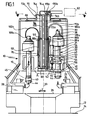
- An embodiment of a machine tool according to the invention shown in Fig. 1, comprises a whole with 10th designated machine frame, which with a base 12 stands on a footprint 14. On the base 12 rests on a machine stand designated as a whole with 16 which a spindle drum designated as a whole by 18 a drum axis 20 is rotatably supported, the drum axis 20 preferably approximately perpendicular to the footprint 14 runs.
- the spindle drum 18 is one with an end face 22 Working space 24 facing, which between the end face 22nd and an upper side 26 of the base frame 12.
- Working space 24 are stationary on the one hand on the base frame 12 arranged tool slide 28 is provided, which preferably in an X-axis running radially to the drum axis 20 are movable and several relative to the base 12 stationary, preferably at equal angular intervals Define spindle stations, two of which are shown in FIG. 1 opposite spindle stations are shown.
- Machining devices 30 are provided, which preferably with their quill 32 in the direction of a parallel to Drum axis 20 extending Z-axis slidably mounted are.
- Each of the work spindles 30 carries one together with this movable spindle drive 34 and an actuator 36 for a workpiece chuck 40, which on an end 42 of the work spindle facing the work area 30 is arranged and in which a workpiece 44 can be inserted is that about an approximately vertical spindle axis 45 for Machining in the spindle stations is rotatable.
- the quills 32 are spaced two apart arranged end plates 46 and 48 of the spindle drum 18 in Slidably guided in the direction of the Z axis and via an as Whole with 50 designated linear drive in this direction movable.
- the linear drive 50 comprises on the one hand in the Spindle drum 18 rotatably mounted and approximately parallel to Drum axis 20 extending threaded spindle 52 which a Z-axis drive 54 arranged on the spindle drum 18 is drivable.
- the threaded spindle 52 passes through one Spindle nut 56, which is fixed to the holder 58 each sleeve 32 of the respective work spindle 30 connected is so that by turning the threaded spindle 52nd the spindle nut 56 and with this the quill 32 in the direction the Z axis and thus movable parallel to the drum axis 20 is.
- Spindle drives 34 and actuators 36 of the Working spindles 30 and the Z-axis drives 54 take place via a rotary supply unit 60, which is a connection between one indicated only schematically by dashed lines
- Control and supply device 62 which is either stationary is arranged on the machine frame 10 or next to it, and of the rotatable spindle drum 18.
- the rotary supply unit 60 is in one Space 64 near drum axis 20 extending around drum axis 20 arranged and comprises one on the work space 24th opposite side of the spindle drum 18 provided Cover 66 of the machine stand 16 arranged stationary Holder 70, which, for example, in the form of a formed perpendicular to the drum axis 20 plate is.
- first wiring harness sections 72a, 72b and 72c which with their ends 74a, 74b and 74c on the stationary holder 70 immobile at least in the direction of the drum axis 20 are fixed.
- the first wiring harness sections 72a, 72b and 72c run in a basic position of the drum 18 to the machine frame 10 parallel to the drum axis 20 in Direction of the end face 22 of the spindle drum 18 in one central shaft 76 of the spindle drum 18 up to an intermediate holder 80 shown in FIGS. 1, 2 and 3 which the first wiring harness sections 72a, 72b and 72c with their intermediate holder ends 78a, 78b and 78c are fixed.
- These second wiring harness sections 82a, 82b and 82c then run in the basic position of the spindle drum 18 again starting approximately from the intermediate holder 80 parallel to the drum axis 20 in the direction of the cover 66 to to a rotatably connected to the spindle drum 18 and thus with this rotating holder 90, which preferably is also designed as a plate and for example in a central area between the intermediate holder 80 and the stationary holder 70 is arranged.
- the rotating holder 90 preferably sits on one of the ones Working space 24 opposite side of the spindle drum 18 extending sleeve 92 and the second harness sections 82a, 82b and 82c are with their rotating ends 88a, 88b and 88c held on the rotating holder 90.
- the guide tube in the Region of the lower end 102 a projecting radially outward Stop segment 108 which at its bow ends extending in the radial direction to the drum axis 20 Forms stop surfaces 110a and 110b, which limit the Rotation of the intermediate holder 80 in radial direction Direction to the drum axis 20 extending stop surfaces 112a and 112b of the flange segment 106 cooperate.
- the end faces 110a and 112a facing each other as well 110b and 112b are shown in FIG. 3 Basic position of the spindle drum 18 and thus also the Intermediate holder 80 at equal angular distances W1 from each other arranged.
- the guide tube 100 is also still with the lower end 102 by a centering body engaging in the guide tube 100 114 centered to the drum axis 20, the Centering body 114 via a the central shaft 76 of the Spindle drum in the area of the end face 22 closing the same End plate 116 centered on the spindle drum 18 held and rotatably connected to this.
- the centering body 114 also has a support flange 118, which runs annularly to the drum axis 20 and on which the intermediate holder 80 with an annular flange surface 120 can be placed in the basic position.
- centering body 114 is still with one Drum axis 20 provided cylindrical guide surface 122 which the intermediate holder 80 with a flange segment 124 is guided close, the flange segment 124 preferably flange segment 106 with respect to drum axis 20 is arranged opposite.
- the centering body 114 also has a radial one Comb arch 126 projecting outside over the cylindrical surface 122 which, in the radial direction to the drum axis 20 extending end surfaces 128a and 128b is provided, which also extending in the radial direction to the drum axis 20 End surfaces 130a and 130b of the flange segment 124 are arranged facing, in the basic position of the Intermediate holder 80 relative to the spindle drum 18, the end faces 128a and 130a and 128b and 130b equal angular distances W2 have each other.
- the intermediate holder 80 is in the solution according to the invention both with respect to the machine stand 16 and opposite the spindle drum 18 freely rotatable, although one Limitation of the maximum twist through the angular distances W1 and W2 is specified.
- the basic position of the spindle drum 18 relative to the Machine stand 16 is chosen so that starting from this Basic position of the spindle drum relative to the machine stand can be rotated by a maximum of 180 ° in a direction of rotation D1 and also in an opposite direction of rotation D2 maximum 180 °, that is, a total of one rotation of the Spindle drum 18 relative to the machine stand 16 by one An angle of less than 360 ° is possible.
- the basic position is chosen so that in this Wiring section sections 72a, 72b and 72c and 82a, 82b and 82c are not twisted, so that, for example, in the case of Harness sections 72a and 72b twist them by an angle of maximum 180 ° in the direction of rotation D1 and a maximum of 180 ° in the opposite direction of rotation D2 can be done.
- the solution according to the invention is the Provided that both a twist of the first Harness sections 72a and 72b as well as the second Harness sections 82a and 82b should be made to total the twisting of the first line section 72a, b and the second line section 82a, b to keep as low as possible.
- the twisting of the first line section should 72a, b and the second line section 82a, b be approximately the same size per unit length, so that the maximum twist of the intermediate holder end 78a, b of the first line section 72a, b relative to stationary end 74a, b to the relative rotation of the co-rotating end 88a, b of the second line section 82a, b relative to the intermediate holder end 84a, b behaves as the length of the first line section 72a, b between ends 74a, b and 78a, b to the Length of the second line section 82a, b between the ends 84a, b and 88a, b.
- the angular distances W1 are also maximum rotation and W2 dimensioned, namely so that they the intended correspond to maximum rotations, so that at maximum rotation the spindle drum 18 starting from the basic position in the direction of rotation D1, the first line section 72a, b are rotated by the angle W1 and the second line section 82a, b by the angle W2.
- Angle W1 and W2 is due to the end faces 110a and 112a and 128a and 130a the rotation of the intermediate holder 80 relative to the guide tube 100 and thus to the stationary holder 70 or relative to the centering body 114 and thus to the spindle drum 18 limited, so that at maximum rotation of the Spindle drum 18 in the direction D1 on the one hand the end faces 110a and 112a and on the other hand the end faces 128b and 130b abut one another and thus the intermediate holder 80 held in a rotational position relative to the basic position which is opposite the stationary holder 80 by the angle W1 is rotated and with respect to the spindle drum 18 Angle W2.
- a rotation in the direction of rotation D2 is in the same way possible, the rotation of the intermediate holder 80 at maximum rotated spindle drum 18 by the angle W1 the stationary holder 70 and the angle W2 the spindle drum 18 is done.
- the even twist of the first line section 72a, b and the second line section 82a, b per unit length also means that the first Harness sections 72a, b and the second harness sections 82a, b by substantially the same amount shorten, so that overall in addition to the rotation of the Intermediate holder 80 also a displacement of the same in Direction of the drum axis 20, namely to the stationary holder 70 out there.
- the guide tube 100 is like this trained that its end face 140 in the basic position of the intermediate holder 80 at a distance from a surface 142 the same stands, so that the intermediate holder 80 in the direction of stationary holder 70 can move, but still guided on the centering body 114 and on the guide tube 100 is.
- a fixation is preferred the ends 78a, b of the first wiring harness sections 72a, b and the ends 84a, b of the second wiring harness sections 82a, b on the intermediate holder 80 by means of the intermediate holders 80 brackets 144a, b and 146a, b realized, which each have the two ends 78a, b and 84a, b clamp at the same time and thus fix firmly.
- the ends 78a, b are connected to the ends 84a, b via an arch 150a which represents an intermediate deflection or 150b of the respective wiring harness, so that overall the wiring harness sections 72a, b and 82a, b over the arches 150a, b are connected to each other and by means of a continuous Harness 170 are realizable.
- the wiring harnesses 72a, b are preferably and 74a, b about electrical wiring harnesses in which preferably Single cores of the same, lying freely next to each other without a sheath are arranged for easier twisting of the wiring harnesses.
- the wiring harnesses 72c and 82c are, for example to hose lines for feeding fluidic Power to actuators 36, wherein a supplying wiring harness is provided, with which all Actuators 36 are connected, the Actuators still valves for switching the have fluidic energy, which is sensitive to torsion are.
- torsion sensitive Hose lines provided that in the region of the ends 74c and 78c and 84c and 88c each have rotary connections 160 are provided which allow torsion of the Avoid wiring harness sections 72c and 82c.
- This Slewing rings 160 are, for example, in the area of the ends 78c and 84c with a deflection channel 162 as an intermediate deflection 150c having deflecting body 164 connected, which is firmly mounted on the intermediate holder 80 and on which the rotary connections 160 are arranged.
- a wiring harness 170a is provided so that, as in Fig. 3 and 4, for example eight with eight spindles Wiring strands 170a of the rotary connection unit 60 are required are, the first wiring harness sections 72a on a to the drum axis 20 coaxial cylinder surface 172 in equal angular distances are arranged and essentially in this cylindrical surface 172 parallel to Extend drum axis 20 to intermediate bracket 80 (Figs. 3 and 4) and their second wiring harness sections 82a run in a cylindrical surface 173 (FIG. 3).
- each work spindle Z-axis drive 54 a variety of wiring harnesses 170b with first wiring harness sections 72b required, all on a further cylinder jacket surface 176 are arranged and in the area of the stationary Holder 70 also with brackets 178 at its ends 74b are fixed (Fig. 4).
- All second line segment sections 82a and 82b then lie also on cylinder surfaces 177 shown in FIG. 3, each with even larger radii than the cylinder surface 172 and 176.
- the first wiring harness sections 72c also run in FIG a cylinder surface 180 specially provided for this and also the corresponding second line section 82c run in a specially designed for this Cylinder jacket surface 181, which has a larger radius than the cylinder surface 180.
- the one designed as a fluid line also forms Harness 170c a U-shaped bend 182c Supply of a work spindle.
Landscapes
- Engineering & Computer Science (AREA)
- Mechanical Engineering (AREA)
- Machine Tool Units (AREA)
- Electrical Discharge Machining, Electrochemical Machining, And Combined Machining (AREA)
- Automatic Tool Replacement In Machine Tools (AREA)
Applications Claiming Priority (2)
| Application Number | Priority Date | Filing Date | Title |
|---|---|---|---|
| DE19835954A DE19835954A1 (de) | 1998-08-08 | 1998-08-08 | Werkzeugmaschine |
| DE19835954 | 1998-08-08 |
Publications (3)
| Publication Number | Publication Date |
|---|---|
| EP0979706A2 true EP0979706A2 (fr) | 2000-02-16 |
| EP0979706A3 EP0979706A3 (fr) | 2001-06-06 |
| EP0979706B1 EP0979706B1 (fr) | 2004-03-31 |
Family
ID=7876916
Family Applications (1)
| Application Number | Title | Priority Date | Filing Date |
|---|---|---|---|
| EP99114201A Expired - Lifetime EP0979706B1 (fr) | 1998-08-08 | 1999-07-23 | Machine-outil |
Country Status (3)
| Country | Link |
|---|---|
| US (1) | US6158312A (fr) |
| EP (1) | EP0979706B1 (fr) |
| DE (2) | DE19835954A1 (fr) |
Families Citing this family (7)
| Publication number | Priority date | Publication date | Assignee | Title |
|---|---|---|---|---|
| DE19916212C2 (de) * | 1999-04-10 | 2003-07-10 | Schuette Alfred H Gmbh & Co Kg | Mehrspindelige Werkzeugmaschine, insbesondere Mehrspindeldrehautomat |
| DE59913199D1 (de) * | 1999-12-01 | 2006-05-04 | Index Werke Kg Hahn & Tessky | Werkzeugmaschine |
| EP1251994B1 (fr) * | 2000-02-01 | 2008-08-06 | Emmegi S.A. Luxembourg, Lugano Branch | Systeme destine a la mise en oeuvre d'operations mecaniques |
| DE10153807A1 (de) * | 2001-11-05 | 2003-05-28 | Emag Maschfab Gmbh | Werkzeugmaschine |
| DE10333051A1 (de) * | 2003-07-18 | 2005-02-03 | Grob-Werke Burkhart Grob E.K. | Spanabhebende Bearbeitungsmaschine |
| DE102009048012A1 (de) * | 2009-10-02 | 2011-04-14 | Kapp Gmbh | Verfahren zum Betreiben einer Verzahnungs- oder Profilschleifmaschine und Verzahnungs- oder Profilschleifmaschine |
| US9120192B2 (en) * | 2012-03-27 | 2015-09-01 | Emag Holding Gmbh | Dual-spindle machining apparatus |
Citations (1)
| Publication number | Priority date | Publication date | Assignee | Title |
|---|---|---|---|---|
| DE19622475A1 (de) | 1996-06-05 | 1997-12-11 | Index Werke Kg Hahn & Tessky | Werkzeugmaschine |
Family Cites Families (18)
| Publication number | Priority date | Publication date | Assignee | Title |
|---|---|---|---|---|
| US1804971A (en) * | 1925-05-02 | 1931-05-12 | Bullard Co | Multiple spindle center turning machine |
| US2635325A (en) * | 1948-01-12 | 1953-04-21 | Rheem Mfg Co | Vertical automatic machine tool |
| US2668557A (en) * | 1950-03-21 | 1954-02-09 | American Tool Works Co | Conduit system for machine tools |
| US2568667A (en) * | 1950-04-08 | 1951-09-18 | Cleveland Hobbing Machine Co | Machine tool |
| US2892388A (en) * | 1951-07-24 | 1959-06-30 | Giddings & Lewis | Multiple line feed for translatable machine elements |
| US3260140A (en) * | 1963-11-26 | 1966-07-12 | William G Burge | Vertical boring mills |
| US4185366A (en) * | 1973-12-06 | 1980-01-29 | Wickman Machine Tool Sales Ltd. | Spindle drives for multi spindle lathes |
| GB1523876A (en) * | 1974-09-12 | 1978-09-06 | Wickmann Machine Tool Sales Lt | Multi spindle lathes |
| GB1559849A (en) * | 1975-12-13 | 1980-01-30 | Wickman Mach Tool Sales Ltd | Controls for molti spindle lathes |
| GB1594233A (en) * | 1977-02-19 | 1981-07-30 | Wickman Mach Tool Sales Ltd | Electrical controls for multispindle lathes |
| DE3025638C2 (de) * | 1980-07-07 | 1982-08-12 | Fa. Gottlieb Gühring, 7470 Ebingen | Rundschalttisch-Maschine |
| DE3275709D1 (en) * | 1981-12-28 | 1987-04-23 | Azypatent Ag | Machine with an intermittently rotating table for working and assembly of high-precision parts |
| WO1985000770A1 (fr) * | 1983-08-06 | 1985-02-28 | Index-Werke Komm.-Ges. Hahn & Tessky | Tour automatique multibroche |
| IT1216603B (it) * | 1988-04-20 | 1990-03-08 | Cucchi Pietro & C | Dispositivo di comando dell'avanzamento di barre metalliche, con distributore e piu' motori idraulici, perl'alimentazione di un tornio automatico a mandrini multipli. |
| DE3844337A1 (de) * | 1988-12-30 | 1990-07-05 | Index Werke Kg Hahn & Tessky | Werkzeugmaschine mit gekuehlter motorspindel |
| DE19504369A1 (de) * | 1995-02-10 | 1996-08-14 | Index Werke Kg Hahn & Tessky | Mehrspindelwerkzeugmaschine |
| DE19514058C2 (de) * | 1995-04-13 | 1998-04-30 | Emag Masch Vertriebs Serv Gmbh | Drehmaschine mit mehreren Spindeln |
| DE19615425C2 (de) * | 1996-04-19 | 1998-09-10 | Chiron Werke Gmbh | Werkzeugmaschine mit einem Drehtisch |
-
1998
- 1998-08-08 DE DE19835954A patent/DE19835954A1/de not_active Ceased
-
1999
- 1999-07-23 DE DE59909002T patent/DE59909002D1/de not_active Expired - Fee Related
- 1999-07-23 EP EP99114201A patent/EP0979706B1/fr not_active Expired - Lifetime
- 1999-08-06 US US09/369,967 patent/US6158312A/en not_active Expired - Fee Related
Patent Citations (1)
| Publication number | Priority date | Publication date | Assignee | Title |
|---|---|---|---|---|
| DE19622475A1 (de) | 1996-06-05 | 1997-12-11 | Index Werke Kg Hahn & Tessky | Werkzeugmaschine |
Also Published As
| Publication number | Publication date |
|---|---|
| US6158312A (en) | 2000-12-12 |
| EP0979706A3 (fr) | 2001-06-06 |
| DE19835954A1 (de) | 2000-02-17 |
| DE59909002D1 (de) | 2004-05-06 |
| EP0979706B1 (fr) | 2004-03-31 |
Similar Documents
| Publication | Publication Date | Title |
|---|---|---|
| EP1863604B1 (fr) | Dispositif de formage libre de profiles allonges, en particulier de tubes, et dispositif combine de formage libre et d'etirage de profiles allonges, en particulier de tubes | |
| EP1964651B1 (fr) | Bras de robot pour un robot industriel | |
| EP2070643B1 (fr) | Unité d'usinage pour une machine de forage et de fraisage | |
| DE3419877A1 (de) | Handhabungseinrichtung | |
| DE3631024C2 (fr) | ||
| DE3419849A1 (de) | Handhabungseinrichtung | |
| EP0649687B1 (fr) | Machine à cintrer les tubes | |
| EP0672480A1 (fr) | Système de transport | |
| DE102010028032B4 (de) | Werkzeugmaschine mit zusätzlichem Zuganker | |
| EP1459816B1 (fr) | Dispostif de cintrage avec outil de cintrage à plusieurs niveaux, unité à machoires de serrage et unité de support à glissières pour un tel dispositif de cintrage | |
| EP3943239B1 (fr) | Machine-outil et procédé de fonctionnement de la machine-outil | |
| DE3210630A1 (de) | Selbsttaetige zufuehrvorrichtung fuer stangenmaterial zu werkzeugmaschinen | |
| DE19850452A1 (de) | Haltevorrichtung für Schaltverbindungen und Rohrleitungen eines Industrieroboters | |
| DE10116994A1 (de) | Werkzeugmaschine | |
| EP3766640B1 (fr) | Pied magnétique | |
| DE19506721A1 (de) | Rohrbiegeeinrichtung | |
| EP0564842B1 (fr) | Machine-outil avec table tournante | |
| EP0979706B1 (fr) | Machine-outil | |
| DE102009046939B4 (de) | Werkzeugmaschine | |
| DE102007031503A1 (de) | Werkstückfördervorrichtung einer Werkzeugmaschine | |
| EP0811464B1 (fr) | Machine-outil | |
| DE3241844C1 (de) | Stanzmaschine mit Revolvertrommel | |
| DE69817570T2 (de) | Drehantrieb für einem arm, wie einen roboterarm, um eine vertikalachse und handhabungsroboter mit einem derartigen antrieb | |
| DE2123097B2 (de) | Werkzeughalter zur Halterung eines Spleißgeräts | |
| EP2289665A1 (fr) | Machine-outil dotée d'un dispositif de changement d'outil |
Legal Events
| Date | Code | Title | Description |
|---|---|---|---|
| PUAI | Public reference made under article 153(3) epc to a published international application that has entered the european phase |
Free format text: ORIGINAL CODE: 0009012 |
|
| AK | Designated contracting states |
Kind code of ref document: A2 Designated state(s): CH DE ES FR IT LI |
|
| AX | Request for extension of the european patent |
Free format text: AL;LT;LV;MK;RO;SI |
|
| PUAL | Search report despatched |
Free format text: ORIGINAL CODE: 0009013 |
|
| AK | Designated contracting states |
Kind code of ref document: A3 Designated state(s): AT BE CH CY DE DK ES FI FR GB GR IE IT LI LU MC NL PT SE |
|
| AX | Request for extension of the european patent |
Free format text: AL;LT;LV;MK;RO;SI |
|
| 17P | Request for examination filed |
Effective date: 20011203 |
|
| AKX | Designation fees paid |
Free format text: CH DE ES FR IT LI |
|
| GRAP | Despatch of communication of intention to grant a patent |
Free format text: ORIGINAL CODE: EPIDOSNIGR1 |
|
| GRAS | Grant fee paid |
Free format text: ORIGINAL CODE: EPIDOSNIGR3 |
|
| GRAA | (expected) grant |
Free format text: ORIGINAL CODE: 0009210 |
|
| AK | Designated contracting states |
Kind code of ref document: B1 Designated state(s): CH DE ES FR IT LI |
|
| PG25 | Lapsed in a contracting state [announced via postgrant information from national office to epo] |
Ref country code: FR Free format text: LAPSE BECAUSE OF FAILURE TO SUBMIT A TRANSLATION OF THE DESCRIPTION OR TO PAY THE FEE WITHIN THE PRESCRIBED TIME-LIMIT Effective date: 20040331 |
|
| REG | Reference to a national code |
Ref country code: CH Ref legal event code: EP |
|
| REF | Corresponds to: |
Ref document number: 59909002 Country of ref document: DE Date of ref document: 20040506 Kind code of ref document: P |
|
| REG | Reference to a national code |
Ref country code: CH Ref legal event code: NV Representative=s name: KIRKER & CIE SA |
|
| PG25 | Lapsed in a contracting state [announced via postgrant information from national office to epo] |
Ref country code: ES Free format text: LAPSE BECAUSE OF FAILURE TO SUBMIT A TRANSLATION OF THE DESCRIPTION OR TO PAY THE FEE WITHIN THE PRESCRIBED TIME-LIMIT Effective date: 20040712 |
|
| PLBE | No opposition filed within time limit |
Free format text: ORIGINAL CODE: 0009261 |
|
| STAA | Information on the status of an ep patent application or granted ep patent |
Free format text: STATUS: NO OPPOSITION FILED WITHIN TIME LIMIT |
|
| EN | Fr: translation not filed | ||
| 26N | No opposition filed |
Effective date: 20050104 |
|
| PGFP | Annual fee paid to national office [announced via postgrant information from national office to epo] |
Ref country code: IT Payment date: 20060731 Year of fee payment: 8 |
|
| PGFP | Annual fee paid to national office [announced via postgrant information from national office to epo] |
Ref country code: CH Payment date: 20061006 Year of fee payment: 8 |
|
| REG | Reference to a national code |
Ref country code: CH Ref legal event code: PL |
|
| PG25 | Lapsed in a contracting state [announced via postgrant information from national office to epo] |
Ref country code: LI Free format text: LAPSE BECAUSE OF NON-PAYMENT OF DUE FEES Effective date: 20070731 Ref country code: CH Free format text: LAPSE BECAUSE OF NON-PAYMENT OF DUE FEES Effective date: 20070731 |
|
| PGFP | Annual fee paid to national office [announced via postgrant information from national office to epo] |
Ref country code: DE Payment date: 20080822 Year of fee payment: 10 |
|
| PG25 | Lapsed in a contracting state [announced via postgrant information from national office to epo] |
Ref country code: IT Free format text: LAPSE BECAUSE OF NON-PAYMENT OF DUE FEES Effective date: 20070723 |
|
| PG25 | Lapsed in a contracting state [announced via postgrant information from national office to epo] |
Ref country code: DE Free format text: LAPSE BECAUSE OF NON-PAYMENT OF DUE FEES Effective date: 20100202 |