EP0979662B1 - Mundstück zur Verabreichung von Druckgasen an einen Verbraucher - Google Patents
Mundstück zur Verabreichung von Druckgasen an einen Verbraucher Download PDFInfo
- Publication number
- EP0979662B1 EP0979662B1 EP99115901A EP99115901A EP0979662B1 EP 0979662 B1 EP0979662 B1 EP 0979662B1 EP 99115901 A EP99115901 A EP 99115901A EP 99115901 A EP99115901 A EP 99115901A EP 0979662 B1 EP0979662 B1 EP 0979662B1
- Authority
- EP
- European Patent Office
- Prior art keywords
- mouthpiece
- vestibular shield
- gases
- user
- shield
- Prior art date
- Legal status (The legal status is an assumption and is not a legal conclusion. Google has not performed a legal analysis and makes no representation as to the accuracy of the status listed.)
- Expired - Lifetime
Links
Images


Classifications
-
- A—HUMAN NECESSITIES
- A61—MEDICAL OR VETERINARY SCIENCE; HYGIENE
- A61M—DEVICES FOR INTRODUCING MEDIA INTO, OR ONTO, THE BODY; DEVICES FOR TRANSDUCING BODY MEDIA OR FOR TAKING MEDIA FROM THE BODY; DEVICES FOR PRODUCING OR ENDING SLEEP OR STUPOR
- A61M16/00—Devices for influencing the respiratory system of patients by gas treatment, e.g. mouth-to-mouth respiration; Tracheal tubes
- A61M16/08—Bellows; Connecting tubes ; Water traps; Patient circuits
-
- A—HUMAN NECESSITIES
- A61—MEDICAL OR VETERINARY SCIENCE; HYGIENE
- A61M—DEVICES FOR INTRODUCING MEDIA INTO, OR ONTO, THE BODY; DEVICES FOR TRANSDUCING BODY MEDIA OR FOR TAKING MEDIA FROM THE BODY; DEVICES FOR PRODUCING OR ENDING SLEEP OR STUPOR
- A61M16/00—Devices for influencing the respiratory system of patients by gas treatment, e.g. mouth-to-mouth respiration; Tracheal tubes
- A61M16/04—Tracheal tubes
- A61M16/0488—Mouthpieces; Means for guiding, securing or introducing the tubes
- A61M16/049—Mouthpieces
- A61M16/0493—Mouthpieces with means for protecting the tube from damage caused by the patient's teeth, e.g. bite block
-
- A—HUMAN NECESSITIES
- A61—MEDICAL OR VETERINARY SCIENCE; HYGIENE
- A61M—DEVICES FOR INTRODUCING MEDIA INTO, OR ONTO, THE BODY; DEVICES FOR TRANSDUCING BODY MEDIA OR FOR TAKING MEDIA FROM THE BODY; DEVICES FOR PRODUCING OR ENDING SLEEP OR STUPOR
- A61M16/00—Devices for influencing the respiratory system of patients by gas treatment, e.g. mouth-to-mouth respiration; Tracheal tubes
- A61M16/04—Tracheal tubes
- A61M16/0488—Mouthpieces; Means for guiding, securing or introducing the tubes
- A61M16/049—Mouthpieces
- A61M16/0495—Mouthpieces with tongue depressors
-
- A—HUMAN NECESSITIES
- A61—MEDICAL OR VETERINARY SCIENCE; HYGIENE
- A61M—DEVICES FOR INTRODUCING MEDIA INTO, OR ONTO, THE BODY; DEVICES FOR TRANSDUCING BODY MEDIA OR FOR TAKING MEDIA FROM THE BODY; DEVICES FOR PRODUCING OR ENDING SLEEP OR STUPOR
- A61M16/00—Devices for influencing the respiratory system of patients by gas treatment, e.g. mouth-to-mouth respiration; Tracheal tubes
- A61M16/08—Bellows; Connecting tubes ; Water traps; Patient circuits
- A61M16/0816—Joints or connectors
- A61M16/0825—Joints or connectors with ball-sockets
Definitions
- This invention relates to a mouthpiece for the oral delivery of air in continuous positive airway pressure (CPAP) treatments of sleeping disorders such as sleep apnea.
- CPAP continuous positive airway pressure
- CPAP continuous positive airway pressure
- EP 818, 213 shows an apparatus for oral delivery of air in a CPAP treatment.
- the apparatus includes a mouthpiece adapted to fit inside the mouth between the roof of the mouth, the hard palate, and the tongue, and having a periphery which can be gripped between the teeth. It is thought by the applicants that this is significantly more intrusive than is necessary and is liable to movement and consequent discomfort (although not outright removal) under the relaxation of sleep. It has the additional disadvantage that with the user fully relaxed, such as in the case of sleep, a distension in the user's jaw and subsequent opening of the mouth can reduce the sealing effectiveness of the mouthpiece and reduce the efficacy of the CPAP treatment.
- WO 90/03199 discloses an orthodontic device which is adapted to be gripped between the jaws of a user and to accommodate the user's teeth within a series of upper and lower cavities.
- a base member of the mouthpiece is shaped and fits against the hard palate of the user.
- This mouthpiece again has the disadvantage of requiring custom orthodontic fitting.
- the mouthpiece is substantially rigid in the vestibule regions of the mouth. The mouthpiece is clamped in place by an outer shield which engages the outside of the user's lips.
- mouthpiece designs are shown for example by use in self contained underwater breathing apparatus systems, for example as depicted in United States Patent No. 4,862,909.
- This mouthpiece is a mouth guard type and is clamped between the teeth.
- a flange extends both in front of and behind the teeth.
- EP-A2-0 845 277 shows the features of the preamble of claim 1.
- Prior art mouthpieces are not well adapted for use in CPAP treatments because they are intended for conscious gripping by the user, and have been found subject to accidental removal with a user in a completely relaxed state such as sleep.
- the present invention overcomes this problem and present several other advantages which will become apparent upon a reading of the attached specification, in combination with a study of the drawings.
- the invention consists in a mouthpiece as defined in claim 1 with a generally rectangularly-shaped vestibular shield having an inner surface and an outer surface, said vestibular shield having a predetermined height which will overlap a user's teeth and gums when positioned in the mouth vestibule of a user, said vestibular shield having a central portion which will extend over a user's front teeth and gums when said central portion of said vestibular shield is positioned between the lips and the teeth of the user, and outer portions extending from said central portion which extend along and overlap at least a portion of the user's back teeth and gums when said outer portions of said vestibular shield are positioned between the cheeks and the teeth of the user; and gases passageway means extending from said outer surface of said vestibular shield to said inner surface of said vestibular shield for allowing the passage of said gases through said mouthpiece.
- the present disclosure provides a system for oral delivery of gases pressurised above ambient to a user and is especially suited for use in the oral delivery of air in continuous positive airway pressure (CPAP) treatments of sleeping disorders such as sleep apnea.
- CPAP continuous positive airway pressure
- the system includes a mouthpiece 1 which is connected by a connection 40 to a breathing circuit 41.
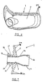
- FIG. 1 shows a first embodiment of the mouthpiece 1 of the present invention.
- the mouthpiece 1 is formed from a vestibular shield 2 which has a gases passage 3, see Figure 5, provided through a central portion 18 thereof.
- a gases inlet 14 is provided on a front or outer surface of the central portion 18 of the vestibular shield 2 and is aligned with the gases passageway 3 provided through the central portion 18 of the vestibular shield 2.
- a gases outlet 15 is provided on a rear or inner face of the central portion 18 of the vestibular shield 2 and is aligned with the gases passage 3 provided through the vestibular shield 2 and with the gases inlet 14.
- the vestibular shield 2 is a generally flat and generally rectangularly-shaped member in front elevation having a curved profile that reflects the curvature of a user's jaw and in turn the curvature of the labial vestibule region (the region between the lips 5,6 and the front teeth 7,8 and the front gums 9,10).
- the vestibular shield 2 is dimensioned such that outer portions 4 extend from the central portion 18 and around the sides of the labial vestibule into the buccal vestibule region (the region between the back teeth and the cheeks).
- the outer portions 4 of the vestibular shield 2 have rounded upper and lower edges 13.
- the vestibular shield 2 has a vertical dimension such that the upper and lower edges 11, 12 extend beyond the margins of the teeth 7, 8 to overlap the gums 9, 10 in the labial vestibule region.
- the vertical dimension is generally consistent along the horizontal length of the vestibular shield 2 such that the upper and lower edges 11, 12 of the vestibular shield extend beyond the margins of the back teeth in the buccal vestibule region to overlap the gums of the back teeth.
- the vertical and horizontal dimension of the vestibular shield 2 of the mouthpiece 1 is particularly significant in the CPAP application because the vestibular shield 2 provides a larger sealing area (in this case between the lips and the outer surface of the vestibular shield 2) than prior art oral devices.
- the vestibular shield 2 With the present mouthpiece 1, the vestibular shield 2 remains substantially sealed within the user's mouth even if the user is fully relaxed and the jaw becomes distended. Sealing of the mouthpiece 1 with the user's mouth is important because of the elevated pressure within the user's mouth during CPAP use. If an oral mouthpiece is not properly sealed within the user's mouth, which can occur with prior art mouthpieces, and sufficient air leaks result, the user can awaken.
- the shape and overall size of the present vestibular shield 2 in relation to a normal mouth opening size requires a conscious effort of lip manipulation by a user to configure the mouth opening for release of the mouthpiece 1 from the vestibule region.
- the vestibular shield 2 of the present invention fits comfortably within the mouth of a user. It is preferred that at least the vestibular shield 2 of the mouthpiece 1 is made from a material that is supple and very soft so that the vestibular shield 2 adapts readily to the form of the user's mouth without significant fitting. Silicone rubber has been found to be an appropriate material. In addition the general shape of the vestibular shield 2 fits naturally within the mouth vestibule, although at a generic level. Each of the upper and lower edges 11,12 of the vestibular shield 2 is provided with notches 16,17 respectively at a center position of the vestibular shield 2 which accommodate the frenal attachments to the upper and lower lips.
- the rounded upper and lower edges 13 of the outer portions 4 conform substantially to the shape of a normal buccal vestibule. If the vestibular shield 2 is made from silicone rubber, it tends to be difficult to trim outer portions 4 of the vestibular shield 2, if required, but it has been found that excellent performance across a range of mouth sizes can be achieved with only a limited selection of vestibular shield 2 sizes.
- a raised area 20 on the inner face of the vestibular shield 2 such raised area 20 having a generally flattened oval shape 21 so that in use, see Figure 5, the raised area 20 abuts against the teeth 7,8 of a user and thereby reduces pressure and potential wear against the gums 9,10 of the user.
- this raised region 20 rigidifies the vestibular shield 2 without effectively increasing the overall thickness, as the raised region 20 lies within what would otherwise be a cavity, and allows the mouthpiece 1 to have a reasonable overall stiffness in bending within its curvature. This reduces the ability for the mouthpiece 1 to be removed accidentally as removal requires deformation in the curvature, while having very supple peripheral outer portions 4 which is important for comfort and sealing efficiency.
- the gases inlet 14, gases passage 3 and the gases outlet 15 are in generally perpendicular alignment through the central portion 18 of the vestibular shield 2 and form a direct path through the vestibular shield 2.
- This configuration of the gases inlet 14, the gases passage 3 and the gases outlet 15 is preferred because of the simplicity of construction.
- This direct path gives less surface area and less flow impingement than more tortuous possible routes and therefore provides a slight reduction in pressure drop from the humidified gases stream passing through the passage during CPAP treatment.
- the gases outlet 15 is formed from a stub tube or conduit and may be integrally formed with the vestibular shield 2, as shown in the drawings, or may be a separate member which is attached by suitable means to the vestibular shield 2.
- the gases outlet 15 is preferably of a generally flattened oval shape and includes a short flange 30 along its upper surface and a short flange 31 along its lower surface such that in use, see Figure 5, a users upper and lower teeth can rest on the gases outlet 15 in the space between the respective flanges 30, 31 and the vestibular shield 2.
- the flange 30 on the upper surface of the gases outlet 15 is preferably laterally short and adjacent the rear edge 32 of the gases outlet 15, while the flange 31 on the lower surface of the gases outlet 15 is preferably curved, more laterally extensive and set back from the rear edge 32 of the gases outlet 15 to promote retention of the lower jaw in a forward position which reduces airway resistance. Retention of the lower jaw in a forward position is a preferred position, but not a necessary one to effect the invention.
- the gases inlet 14 is formed from a stub tube or conduit and may be integrally formed with the vestibular shield 2 or may be a separate member which is attached by suitable means to the vestibular shield 2. As shown in the drawings, the gases inlet 14 is formed from a conduit 34 that is inserted through the gases passage 3 and into the gases outlet 15.
- the inserted conduit 34 which forms the gases inlet 14 is preferably formed of a material which is significantly harder or stiffer than the surrounding supple material of which the vestibular shield 2 is formed. This provides a secure connection to the breathing circuit 41 and provides for durability of the mouthpiece 1.
- a moulded polyethylene tube may be used for the inserted conduit 34.
- the harder plastic material makes it possible to utilise standard breathing circuit connections at the gases inlet 14, and for this reason the inserted conduit 34 preferably merges from a generally flattened oval shape 35 at the outlet proximate to the exit of the gases outlet 15 to a circular shape 36 at the inlet.
- the inserted conduit 34 is preferably surrounded by the gases outlet 15 which is made of the more supple material, so that the surface 37 of the gases outlet 15 presented to the user is soft and pliable, while the hard plastic inserted conduit 34 ensures that the breathing passageway formed by the gases outlet 15 will not be accidentally collapsed by pressure from the jaws of the user.
- the gases inlet 14 extends between the lips 5, 6 of the user.
- One possible alternative configuration (not illustrated) of gases distribution through the mouthpiece 1 would be to route the gases from the centrally located gases inlet 14, through an internally located network of distribution passages to the outer portions 4 of the vestibular shield 2, whereupon the gases would exit though outlet apertures in the rear, or inner, surface of the vestibular shield 2.
- the apertures would be facing substantially inward towards the respective openings between the upper and lower jaw, behind the rearmost teeth when the jaw is closed.
- the vestibular shield 2 of the mouthpiece 1 is formed with a series of concentric ribs 29 at and following the periphery thereof.
- a person fitting the mouthpiece 1 for a user will trim back the periphery of the vestibular shield 2, for example by cutting with a sharp knife or scissors, removing one or more of the ribs 29, using the valleys between the ribs 29 as a guide, as necessary for achieving a comfortable fit of the vestibular shield 2 within the user's vestibule.
- the ribs 29 serve primarily as a guide for trimming, but also the valleys provide a further element of suppleness to the periphery of the vestibular shield 2.
- the mouthpiece 50 includes a vestibular shield 2 substantially in accordance with the earlier embodiments.
- a gases passageway extends through the vestibular shield from an inlet 51 to an outlet 52 in much the same way as with the earlier embodiments.
- In the preferred embodiment 51 is provided by a flattened oval-shaped connector 53.
- the outlet 52 has an even more laterally extended flattened oval shape 54.
- the major differences between the mouthpiece 50 and the embodiments described above are provided on the inner face of the vestibular shield.
- the mouthpiece 50 includes a tongue depressor 55 extending from the inner face of the vestibular shield 2. The operation of the tongue depressor will be described further on with reference to Figure 11.
- the tongue depressor includes a vertical stiffening flange 56 centrally located on its upper surface and extending from the gases outlet 52. In use gases flow easily around the stiffening flange 56 effectively bifurcating the gases outlet 52.
- the tongue depressor 55 further includes a pair of vertically extending spacers 57 which in use may abut against the roof of the wearer's mouth and ensure that the tongue cannot completely block the air passageway.
- the sealing effect of the vestibular shield 2 against the lips of the user is enhanced by providing teeth abutments of significantly increased thickness than the raised area 20 of the earlier embodiments.
- an upper teeth abutment 58 and a lower teeth abutment 59 are provided, with the lower teeth abutment 59 protruding further from the inner face of the vestibular shield 2 than the upper teeth abutment 58. This difference serves to match the typical over-bite of most users.
- the abutments 58 and 59 are not required to be wider than the gases outlet 52.
- a notch 60 is provided centrally in the upper edge of the vestibular shield 2 to accommodate the upper frenal attachment.
- a slight bead 61 is provided around the edge of the vestibular shield 2 for user comfort, with the vestibular shield 2 otherwise being very thin for additional suppleness.
- the mouthpiece 50 is preferably formed by over-moulding a soft and supple material part 70 over a stiffer material part 67.
- the passageway-forming insert preferably includes a pair of upper and lower vertical flanges 63 and 64 to fully engage within the supple material.
- the passageway-forming insert 67 includes the vertically extending stiffening flange 56 of the tongue depressor 55, together with a curved planar portion 71 forming the backbone of the tongue depressor 55.
- the vertically extending spacers 57 are of the soft and supple material and are part of the over-moulding 70, as are the upper and lower teeth abutments 58 and 59.
- connection 40 as provided in the present invention between the breathing circuit 41 and the mouthpiece 1 decouples the mouthpiece 1 from the breathing circuit 41.
- the connection 40 is effective in reducing the forces placed on the mouthpiece 1 by the breathing circuit 41 when the user moves around during sleep.
- the breathing circuit 41 is laid across the chest 43 of the user, and may be secured to the user's bed clothes or sleeping garments.
- the breathing circuit 41 is preferably laid on the chest of the user to take the weight of the breathing circuit 41 off of the mouthpiece 1.
- an L-shaped elbow 45 is incorporated in the connection 40.
- the elbow 45 may be incorporated in the mouthpiece 1, however, it is preferred that the mouthpiece 1 be kept small to provide for easier cleaning.
- the elbow 45 is formed at a right angle and provides a positive pressure on the mouthpiece 1 to maintain the mouthpiece 1 in the user's mouth.
- the elbow 45 may include a swivel joint.
- the connection 40 further includes an extremely flexible connecting tube 46 provided between the elbow 45 and the breathing circuit 41.
- the connecting tube 46 is preferably connected to the breathing circuit 41 by a swivel joint 48 for reasons described herein.
- the breathing circuit 41 while flexible, will necessarily be stiff enough to maintain its integrity over comparatively long tuns, while the connecting tube 46, being only a short length, for example 10 centimeters, merely has to span between the user's mouth and chest, and can thereby be made in a manner that would not be suitable for long runs. Furthermore, as a result of the short length of the connecting tube 46, the connecting tube 46 does not need to incorporate significant insulation or heating capability.
- the connecting tube 46 may be formed from a thin plastic membrane supported over a helical or double helical supporting ribs. In such a case, the support makes the connection tube 46 laterally flexible and resistant to torsion.
- the elbow swivel joint 45 allows for movement of the connection tube 46 relative to the mouthpiece 1.
- the swivel joint 48 allows for movement of the connection tube 46 relative to the breathing circuit 41. It is to be understood that one or both of the swivel joints 45, 48 could be eliminated, but the preferred embodiment includes swivel joint 48.
- the present invention provides a system including mouthpiece 1 for oral delivery of CPAP treatment which at once is low cost and effective.
- the mouthpiece 1 used in the present invention does not require custom orthodontic fitting as the mouthpiece 1 does not rely on accurate alignment with the user's teeth or the user's palate to provide location and retention within the user's mouth, but instead resides in the vestibule between the teeth and lips and the teeth and cheeks, and the lateral and vertical extension of the vestibular shield 2 requires that the user's lips be actively manipulated for the vestibular shield 2 to be removed.
- the improved connection 40 to the breathing circuit 41 reduces the forces which tend to pull at the mouthpiece 1.
Claims (29)
- Mundstück zum Zuführen von Gasen in die Mundhöhle eines Verwenders, welches einen im Allgemeinen rechteckförmigen Vorhofschild (2) umfasst, der eine innere Fläche und eine äußere Fläche aufweist, und Gasdurchgangsmittel (3), die sich von der äußeren Fläche des Vorhofschilds (2) zu der inneren Fläche des Vorhofschilds (2) erstrecken, um den Durchtritt von Gasen durch das Mundstück (1) zu erlauben, wobei der Vorhofschild (2) eine vorbestimmte Höhe aufweist, welche die Zähne und das Zahnfleisch eines Verwenders überlappt, wenn dieser im Mundvorhof eines Verwenders angeordnet ist, wobei der Vorhofschild (2) einen Mittelabschnitt (18) aufweist, der sich über die vorderen Zähne und das vordere Zahnfleisch erstreckt, wenn der Mittelabschnitt (18) des Vorhofschilds (2) zwischen den Lippen und den Zähnen des Verwenders angeordnet ist,
dadurch gekennzeichnet, dass der Vorhofschild vom Mittelabschnitt (18) ausgehende, äußere Abschnitte (4) aufweist, die sich entlang zumindest eines Abschnitts der hinteren Zähne und des hinteren Zahnfleischs des Verwenders erstrecken und diesen überlappen, wenn die äußeren Abschnitte (4) des Vorhofschilds (2) zwischen den Wangen und den Zähnen des Verwenders angeordnet sind; wobei der Vorhofschild (2) sich im Gebrauch dicht gegen die inneren Wände der Lippen und/oder der Wangen des Munds des Verwenders anlegt. - Mundstück gemäß Anspruch 1, welches ferner einen auf der inneren Fläche des Mittelabschnitts (18) des Vorhofschilds (2) vorgesehenen, erhöhten Abschnitt einschließt, wobei der erhöhte Abschnitt dann, wenn der Vorhofschild (2) im Mund eines Verwenders angeordnet ist, ausschließlich mit den Zähnen eines Verwenders in Kontakt tritt.
- Mundstück gemäß Anspruch 2, bei welchem der erhöhte Abschnitt (20) eine im Allgemeinen abgeflachte, ovale Gestalt aufweist.
- Mundstück gemäß Anspruch 2 oder Anspruch 3, bei welchem sich der erhöhte Abschnitt (20) entlang zumindest eines Abschnitts der äußeren Abschnitte (4) erstreckt.
- Mundstück gemäß einem der Ansprüche 1 bis 4, bei welchem der Mittelabschnitt (18) in seinem oberen Rand (11) eine zentral gelegene Kerbe (16) einschließt.
- Mundstück gemäß Anspruch 5, welches ferner in einem unteren Rand (12) des Mittelabschnitts (18) eine zentral gelegene Kerbe (17) einschließt.
- Mundstück gemäß einem der Ansprüche 1 bis 6, bei welchem der Vorhofschild (2) ein im Allgemeinen gebogenes Profil aufweist.
- Mundstück gemäß einem der Ansprüche 1 bis 7, bei welchem die Gasdurchgangsmittel (3) Gaseinlassmittel (14) einschließen, um das Verbinden des Mundstücks (1) mit einer Gaszuführung zu erlauben.
- Mundstück gemäß Anspruch 8, bei welchem die Gaseinlassmittel (14) mit dem Mittelabschnitt (18) des Vorhofschilds (2) verbunden sind.
- Mundstück gemäß Anspruch 9, bei welchem der Vorhofschild (2) aus einem biegsamen Material gebildet ist und die Gaseinlassmittel (14) ein Rohr (34) umfassen, welches aus einem steiferen Material gebildet ist als das biegsame Material, welches zum Bilden des Vorhofschilds (2) verwendet wird, wobei das Rohr (34) am Vorhofschild (2) befestigt ist.
- Mundstück gemäß einem der Ansprüche 1 bis 10, bei welchem die Gasdurchgangsmittel (3) Gasauslassmittel (15) einschließen, um das Ausstoßen von Gasen in den Mund eines Verwenders zu erlauben.
- Mundstück gemäß Anspruch 11, bei welchem die Gasauslassmittel (15) entlang des Mittelabschnitts (18) des Vorhofschilds (2) vorgesehen sind.
- Mundstück gemäß Anspruch 11, bei welchem die Gasdurchgangsmittel (3) Gaseinlassmittel (14) einschließen, um das Verbinden des Mundstücks (1) mit einer Gaszuführung zu erlauben.
- Mundstück gemäß Anspruch 13, bei welchem die Gasauslassmittel (15) zu den Gaseinlassmitteln (14) ausgerichtet sind.
- Mundstück gemäß Anspruch 14, bei welchem die Gaseinlassmittel (14) und die Gasauslassmittel (15) mit dem Mittelabschnitt (18) des Vorhofschilds (2) verbunden sind.
- Mundstück gemäß Anspruch 11, bei welchem die Gasauslassmittel (15) ein im Allgemeinen abgeflachtes, ovalförmiges Rohr (34) sind, welches von der inneren Fläche des Vorhofschilds (2) ausgeht.
- Mundstück gemäß Anspruch 16, bei welchem das im Allgemeinen abgeflachte, ovalförmige Rohr (34) eine obere Fläche und eine untere Fläche aufweist, und die Gasauslassmittel (15) entlang der oberen und/oder der unteren Fläche ferner einen Flansch einschließen, wobei der Flansch vom Vorhofschild (2) beabstandet ist.
- Mundstück gemäß Anspruch 16, bei welchem das im Allgemeinen abgeflachte, ovalförmige Rohr (34) eine obere Fläche und eine untere Fläche aufweist, und die Gasauslassmittel (15) ferner einen sich entlang der oberen Fläche erstreckenden, oberen Flansch (30) einschließen, wobei der obere Flansch (30) vom Vorhofschild (2) beabstandet ist, sowie einen sich entlang der unteren Fläche erstreckenden, unteren Flansch (31), wobei der untere Flansch (31) vom Vorhofschild (2) beabstandet ist.
- Mundstück gemäß Anspruch 18, bei welchem sich der obere Flansch (30) in Nachbarschaft eines hinteren Endes der Gasauslassmittel (15) befindet und der untere Flansch (31) vom hinteren Ende der Gasauslassmittel (15) beabstandet ist, wobei der untere Flansch gebogen ist.
- Mundstück gemäß einem der Ansprüche 1 bis 19, bei welchem die äußeren Abschnitte (4) des Vorhofschilds (2) auf sich eine Mehrzahl von Rippen (30) einschließen.
- Mundstück gemäß Anspruch 20, bei welchem die Rippen (30) auf der äußeren Fläche des Vorhofschilds (2) vorgesehen sind.
- Mundstück gemäß einem der Ansprüche 1 bis 21, bei welchem der Vorhofschild (2) aus einem biegsamen Material gebildet ist.
- Mundstück gemäß einem der Ansprüche 1 bis 22, bei welchem der Vorhofschild (2) im Allgemeinen flach ist.
- Mundstück gemäß einem der Ansprüche 1 bis 23, bei welchem jeder äußere Abschnitt (4) gerundete obere und untere Ränder (13) aufweist.
- Mundstück gemäß Anspruch 2 oder Anspruch 3, bei welchem der erhöhte Abschnitt einen oberen Anlageabschnitt (58) einschließt, um sich gegen die oberen Zähne anzulegen, sowie einen unteren Anlageabschnitt (59), um sich gegen die unteren Zähne anzulegen, und der untere Anlageabschnitt (59) weiter über die innere Fläche des Vorhofschilds (2) erhöht ist als der untere Anlageabschnitt (58).
- Mundstück gemäß einem der Ansprüche 1 bis 25, welches eine Zungenniederdrücksicherung (55) einschließt, die von der Innenseite des Vorhofschilds (2) ausgeht.
- Mundstück gemäß Anspruch 26, bei welchem die Zungenniederdrücksicherung (55) in ihrer unteren Fläche eine konkave Biegung aufweist und steifer ist als die äußeren Abschnitte (4) des Vorhofschilds.
- Mundstück gemäß Anspruch 26 oder Anspruch 27, welches einen oder mehrere sich vertikal erstreckende Abstandhalter (57) einschließt, die von der oberen Fläche der Zungenniederdrücksicherung (55) vorspringen.
- Mundstück gemäß einem der Ansprüche 26 bis 28, bei welchem der Gasdurchgang (3) durch einen Einsatz (67) vorgesehen ist, der aus im Wesentlichen steiferem Material gebildet ist als der Vorhofschild (2), wobei der Einsatz (67) sich durch den Vorhofschild (2) erstreckt, und die Zungenniederdrücksicherung (55) in sich eine Erweiterung des Einsatzes (67) einschließt, die hierfür eine Versteifung (71) bildet.
Applications Claiming Priority (2)
| Application Number | Priority Date | Filing Date | Title |
|---|---|---|---|
| NZ33135598 | 1998-08-13 | ||
| NZ33135598 | 1998-08-13 |
Publications (3)
| Publication Number | Publication Date |
|---|---|
| EP0979662A2 EP0979662A2 (de) | 2000-02-16 |
| EP0979662A3 EP0979662A3 (de) | 2001-09-19 |
| EP0979662B1 true EP0979662B1 (de) | 2007-02-28 |
Family
ID=19926880
Family Applications (1)
| Application Number | Title | Priority Date | Filing Date |
|---|---|---|---|
| EP99115901A Expired - Lifetime EP0979662B1 (de) | 1998-08-13 | 1999-08-12 | Mundstück zur Verabreichung von Druckgasen an einen Verbraucher |
Country Status (4)
| Country | Link |
|---|---|
| EP (1) | EP0979662B1 (de) |
| JP (1) | JP2000051357A (de) |
| AU (1) | AU746574B2 (de) |
| DE (1) | DE69935289T2 (de) |
Families Citing this family (12)
| Publication number | Priority date | Publication date | Assignee | Title |
|---|---|---|---|---|
| US6679257B1 (en) | 1998-08-13 | 2004-01-20 | Fisher & Paykel Limited | Breathing assistance apparatus |
| US6820617B2 (en) | 1998-08-13 | 2004-11-23 | Fisher & Paykel Limited | Breathing assistance apparatus |
| US6457471B1 (en) | 2000-06-30 | 2002-10-01 | Medihale Ltd. | Dual-purpose medical device for upper airway treatment and methods for using same |
| US6981502B2 (en) | 2004-04-01 | 2006-01-03 | Numask, Inc. | Respiratory mask having intraoral mouthpiece with large sealing area and multiple sealing configuration |
| JP2012509107A (ja) * | 2008-11-17 | 2012-04-19 | ザ メトロヘルス システム | 肺換気および粘液除去の組み合わせ装置および方法 |
| JP2013163003A (ja) * | 2012-02-13 | 2013-08-22 | Tagawa Mari | 人工呼吸用陽圧漏れ防止用具 |
| GB2515732B (en) * | 2013-06-20 | 2015-05-27 | Shu Chen Tsai | Respiratory tract bore opening keeping device |
| FR3007292A1 (fr) * | 2013-06-24 | 2014-12-26 | Tsai Shu Chen | Dispositif de maintien de l'ouverture des voies respiratoires |
| JP6225627B2 (ja) * | 2013-10-10 | 2017-11-08 | 住友ベークライト株式会社 | 内視鏡用マウスピース |
| EP2992919A1 (de) | 2014-09-04 | 2016-03-09 | Airway Medical Limited | Multifunktionale Luftwegvorrichtung |
| CN110584579A (zh) * | 2019-10-28 | 2019-12-20 | 南微医学科技股份有限公司 | 口腔开口器及医疗设备 |
| KR102413999B1 (ko) * | 2022-01-13 | 2022-06-27 | 김관현 | 발성 및 호흡 훈련용 마우스피스 및 이를 이용한 발성훈련방법 |
Citations (1)
| Publication number | Priority date | Publication date | Assignee | Title |
|---|---|---|---|---|
| US3139088A (en) * | 1961-01-17 | 1964-06-30 | Jr Ellis A Galleher | Oral inhaler or applicator with sealing means |
Family Cites Families (10)
| Publication number | Priority date | Publication date | Assignee | Title |
|---|---|---|---|---|
| US3670726A (en) * | 1969-09-23 | 1972-06-20 | Becton Dickinson Co | Breathing circuit |
| US4233972A (en) * | 1978-05-08 | 1980-11-18 | Wolfgang Hauff | Portable air filtering and breathing assist device |
| US4270531A (en) * | 1978-12-11 | 1981-06-02 | Blachly Paul H | Oropharyngeal airway and bite block assembly and method of use for closed pulmonary ventilation |
| SE464169B (sv) * | 1988-09-19 | 1991-03-18 | Foereningen Lim Infektionsklin | Munstycke foer anslutning till en respirator |
| US4862909A (en) | 1989-03-03 | 1989-09-05 | Kim Il Y | Drainage pan for liquid waste containers |
| US5333608A (en) * | 1992-09-30 | 1994-08-02 | Sherwood Medical Company | Endotracheal tube for face, chin and neck surgery |
| WO1996003173A1 (fr) * | 1993-01-18 | 1996-02-08 | Michel David | Embout respiratoire intra-buccal anatomique |
| FR2700473B1 (fr) * | 1993-01-18 | 1995-04-07 | Michel David | Embout respiratoire intra-buccal anatomique. |
| US5884625A (en) | 1996-07-09 | 1999-03-23 | Hart; William T. | Oral appliance for delivering gas to the retroglossal area |
| CA2222830C (en) * | 1996-12-02 | 2004-03-30 | Fisher & Paykel Limited | Humidifier sleep apnea treatment apparatus |
-
1999
- 1999-08-10 AU AU43458/99A patent/AU746574B2/en not_active Expired
- 1999-08-12 EP EP99115901A patent/EP0979662B1/de not_active Expired - Lifetime
- 1999-08-12 DE DE69935289T patent/DE69935289T2/de not_active Expired - Lifetime
- 1999-08-13 JP JP11229173A patent/JP2000051357A/ja active Pending
Patent Citations (1)
| Publication number | Priority date | Publication date | Assignee | Title |
|---|---|---|---|---|
| US3139088A (en) * | 1961-01-17 | 1964-06-30 | Jr Ellis A Galleher | Oral inhaler or applicator with sealing means |
Also Published As
| Publication number | Publication date |
|---|---|
| JP2000051357A (ja) | 2000-02-22 |
| AU4345899A (en) | 2000-03-09 |
| EP0979662A2 (de) | 2000-02-16 |
| AU746574B2 (en) | 2002-05-02 |
| DE69935289T2 (de) | 2007-11-22 |
| EP0979662A3 (de) | 2001-09-19 |
| DE69935289D1 (de) | 2007-04-12 |
Similar Documents
| Publication | Publication Date | Title |
|---|---|---|
| US11471639B2 (en) | Respiratory interface with elbow | |
| US6997186B2 (en) | Breathing assistance apparatus | |
| US6679257B1 (en) | Breathing assistance apparatus | |
| EP1729840B1 (de) | Atemmaske mit einem intraoralen mundstück mit grossem verschlussbereich und mehrfach-verschlusskonfiguration | |
| US6295988B1 (en) | Tongue lift and lip seal mouthpiece | |
| CN115400312A (zh) | 患者接口及面罩 | |
| EP0979662B1 (de) | Mundstück zur Verabreichung von Druckgasen an einen Verbraucher | |
| EP3823566B1 (de) | Orales gerät | |
| EP1075848B1 (de) | Mundstück mit extraoralen biegsamen Dichtungsmitteln | |
| KR20220044199A (ko) | 환자 인터페이스 | |
| AU2021107000A4 (en) | Mouthpiece for pap therapy |
Legal Events
| Date | Code | Title | Description |
|---|---|---|---|
| PUAI | Public reference made under article 153(3) epc to a published international application that has entered the european phase |
Free format text: ORIGINAL CODE: 0009012 |
|
| AK | Designated contracting states |
Kind code of ref document: A2 Designated state(s): AT BE CH CY DE DK ES FI FR GB GR IE IT LI LU MC NL PT SE Kind code of ref document: A2 Designated state(s): DE FR GB IT |
|
| AX | Request for extension of the european patent |
Free format text: AL;LT;LV;MK;RO;SI |
|
| PUAL | Search report despatched |
Free format text: ORIGINAL CODE: 0009013 |
|
| AK | Designated contracting states |
Kind code of ref document: A3 Designated state(s): AT BE CH CY DE DK ES FI FR GB GR IE IT LI LU MC NL PT SE |
|
| AX | Request for extension of the european patent |
Free format text: AL;LT;LV;MK;RO;SI |
|
| RIC1 | Information provided on ipc code assigned before grant |
Free format text: 7A 61M 16/06 A, 7A 61M 16/08 B, 7A 61M 16/04 B |
|
| 17P | Request for examination filed |
Effective date: 20011211 |
|
| AKX | Designation fees paid |
Free format text: DE FR GB IT |
|
| 17Q | First examination report despatched |
Effective date: 20040213 |
|
| RAP1 | Party data changed (applicant data changed or rights of an application transferred) |
Owner name: FISHER & PAYKEL HEALTHCARE LIMITED |
|
| RTI1 | Title (correction) |
Free format text: MOUTHPIECE, FOR DELIVERING PRESSURIZED GASES TO A USER |
|
| GRAP | Despatch of communication of intention to grant a patent |
Free format text: ORIGINAL CODE: EPIDOSNIGR1 |
|
| GRAS | Grant fee paid |
Free format text: ORIGINAL CODE: EPIDOSNIGR3 |
|
| GRAA | (expected) grant |
Free format text: ORIGINAL CODE: 0009210 |
|
| AK | Designated contracting states |
Kind code of ref document: B1 Designated state(s): DE FR GB IT |
|
| REG | Reference to a national code |
Ref country code: GB Ref legal event code: FG4D |
|
| REF | Corresponds to: |
Ref document number: 69935289 Country of ref document: DE Date of ref document: 20070412 Kind code of ref document: P |
|
| ET | Fr: translation filed | ||
| PLBE | No opposition filed within time limit |
Free format text: ORIGINAL CODE: 0009261 |
|
| STAA | Information on the status of an ep patent application or granted ep patent |
Free format text: STATUS: NO OPPOSITION FILED WITHIN TIME LIMIT |
|
| 26N | No opposition filed |
Effective date: 20071129 |
|
| REG | Reference to a national code |
Ref country code: FR Ref legal event code: PLFP Year of fee payment: 18 |
|
| PGFP | Annual fee paid to national office [announced via postgrant information from national office to epo] |
Ref country code: IT Payment date: 20160726 Year of fee payment: 18 |
|
| REG | Reference to a national code |
Ref country code: FR Ref legal event code: PLFP Year of fee payment: 19 |
|
| REG | Reference to a national code |
Ref country code: FR Ref legal event code: PLFP Year of fee payment: 20 |
|
| PG25 | Lapsed in a contracting state [announced via postgrant information from national office to epo] |
Ref country code: IT Free format text: LAPSE BECAUSE OF NON-PAYMENT OF DUE FEES Effective date: 20170812 |
|
| PGFP | Annual fee paid to national office [announced via postgrant information from national office to epo] |
Ref country code: FR Payment date: 20180824 Year of fee payment: 20 |
|
| PGFP | Annual fee paid to national office [announced via postgrant information from national office to epo] |
Ref country code: GB Payment date: 20180831 Year of fee payment: 20 |
|
| PGFP | Annual fee paid to national office [announced via postgrant information from national office to epo] |
Ref country code: DE Payment date: 20181031 Year of fee payment: 20 |
|
| REG | Reference to a national code |
Ref country code: DE Ref legal event code: R071 Ref document number: 69935289 Country of ref document: DE |
|
| REG | Reference to a national code |
Ref country code: GB Ref legal event code: PE20 Expiry date: 20190811 |
|
| PG25 | Lapsed in a contracting state [announced via postgrant information from national office to epo] |
Ref country code: GB Free format text: LAPSE BECAUSE OF EXPIRATION OF PROTECTION Effective date: 20190811 |