EP0978680A2 - Système de raccordement haute pression - Google Patents
Système de raccordement haute pression Download PDFInfo
- Publication number
- EP0978680A2 EP0978680A2 EP99114001A EP99114001A EP0978680A2 EP 0978680 A2 EP0978680 A2 EP 0978680A2 EP 99114001 A EP99114001 A EP 99114001A EP 99114001 A EP99114001 A EP 99114001A EP 0978680 A2 EP0978680 A2 EP 0978680A2
- Authority
- EP
- European Patent Office
- Prior art keywords
- connection system
- pressure connection
- channel
- area
- fluid channel
- Prior art date
- Legal status (The legal status is an assumption and is not a legal conclusion. Google has not performed a legal analysis and makes no representation as to the accuracy of the status listed.)
- Withdrawn
Links
- 239000012530 fluid Substances 0.000 claims abstract description 39
- 238000013461 design Methods 0.000 description 3
- 230000036316 preload Effects 0.000 description 2
- 230000015572 biosynthetic process Effects 0.000 description 1
- 238000004519 manufacturing process Methods 0.000 description 1
- 238000000034 method Methods 0.000 description 1
- 238000003801 milling Methods 0.000 description 1
- 238000003825 pressing Methods 0.000 description 1
- 239000000565 sealant Substances 0.000 description 1
- 239000007787 solid Substances 0.000 description 1
- 238000012360 testing method Methods 0.000 description 1
- 238000012549 training Methods 0.000 description 1
- 238000012546 transfer Methods 0.000 description 1
Images

Classifications
-
- F—MECHANICAL ENGINEERING; LIGHTING; HEATING; WEAPONS; BLASTING
- F16—ENGINEERING ELEMENTS AND UNITS; GENERAL MEASURES FOR PRODUCING AND MAINTAINING EFFECTIVE FUNCTIONING OF MACHINES OR INSTALLATIONS; THERMAL INSULATION IN GENERAL
- F16L—PIPES; JOINTS OR FITTINGS FOR PIPES; SUPPORTS FOR PIPES, CABLES OR PROTECTIVE TUBING; MEANS FOR THERMAL INSULATION IN GENERAL
- F16L41/00—Branching pipes; Joining pipes to walls
- F16L41/08—Joining pipes to walls or pipes, the joined pipe axis being perpendicular to the plane of a wall or to the axis of another pipe
- F16L41/082—Non-disconnectable joints, e.g. soldered, adhesive or caulked joints
Definitions
- the present invention relates to a high pressure connection system a first body comprising a first fluid channel and one second body comprising second fluid channel, wherein the first body is at least partially encompassed by the second body and in the Wall of the first body a first and in the wall of the second body a second connection channel for connecting the first fluid channel with the second fluid channel are formed. Furthermore, the invention is based on a high-pressure feed pump with a high-pressure connection system according to the invention directed.
- High-pressure connection systems of the type mentioned at the outset are, for example used when high pressure fluid from a Pipe, a cylinder or the like in an attached thereto High pressure room should be directed.
- the comprehensive high-pressure room second body usually encompasses the first body, for example the tube or the cylinder, being through in the body walls trained connecting channels the transfer of the fluid from the first body into the second body.
- the second connecting channel usually comprises an annulus, the with the second fluid channel, i.e. the high pressure space of the second body, connected is.
- the annulus is arranged so that the first Connection channel opens into the annulus, so that from the first Fluid channel of the first body exiting via the first connecting channel Fluid first flows into the annular space, completely filling it and from there into the second fluid channel forming the high-pressure space penetrates.
- connection point between the first and the second body are often not sufficient Has tightness.
- appropriate sealant is provided at the connection point, which should ensure the required tightness.
- the ring channel can be used first body comprehensive second body are so heavily loaded that this is permanently deformed, causing the connection point to leak becomes. This can also be the case if the one encompassing the first body second body is very solid, since the one in the second Body-formed ring channel a large area of attack for the fluid pressure forms. Due to this large area of attack, this can be under high Fluid under pressure will inflate this channel and cause a leak the junction between the two bodies.
- this object is achieved in that the first body is gripped by the second body under press fit that the Connection channels as to the outside of the first or the second Body-extending branch channels are formed, which are directly with each other are connected, and that the first and / or the second body in the Area of one formed on the outside of the first or second body Outlet opening of the first or the second fluid channel means to increase the press fit between the first and the second body generated contact pressure.
- the first and the second body is designed so that the second body is the first body grips under press fit. This can be done for example by ashrinking process or by pressing the first body into a corresponding Opening of the second body in the manner of a longitudinal press fit respectively.
- the press body forms the second body a pressure body that on the outside of the first body Applies compressive stress. This acts as an external preload Compressive stress on the first body relieves it of high tensions, when the fluid is under extremely high pressure through the two bodies is promoted.
- the second solution is based on the usual ring channel is dispensed with and the two connecting channels are designed as branch channels are immediate, i.e. without the interposition of a ring channel, are interconnected. In this way, the target area significantly reduced for the fluid pressure within the connecting channels, causing an inflation of the connecting channels, as is the case when using of a ring channel can be practically excluded.
- the third solution is that the contact pressure between the first and second body, due to the press fit arises, increased in the area of the outlet openings of the connecting channels becomes. This targeted increase in the contact pressure on the critical Junction between the first and the second body becomes the tightness of a high-pressure connection system designed according to the invention further improved.
- the connecting channels essentially aligned with each other.
- the outlet opening of the first and / or the second connecting channel forming area of the outside of the first and the second body opposite protruding from the adjoining outside. Due to the outward projecting design of the outside in the area of the outlet opening after creating the press fit in Area of this outlet opening increases the pressure preload, whereby the tightness of the connection point is also improved.
- the projecting area versus the turn then connect the set-back area to the outside, which in particular completely surrounds the outlet opening.
- Training is the exit opening of the first and / or region forming the second connecting channel as essentially cylindrical Cantilever with an essentially annular end face Contact area formed.
- This contact area can in particular much smaller than the area of the rest due to the press tension formed contact area between the first and the second body his.
- a recessed area ensures that directly in the area of the outlet openings of the connecting channels, i.e. in the area of the critical connection between the two Bodies, the contact area is reduced and thereby the contact surface the resulting contact pressure against that on the rest Contact area acting contact pressure is increased.
- the invention can be particularly advantageous High pressure connection system used in high pressure feed pumps as described, for example, in Swiss Patent Application No. 1997 1275/97 and in the corresponding EP patent application No. 98 108 103.7 are disclosed.
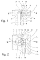
- FIG. 1 which shows a section along the line III-III from FIG. 2, shows a tubular first body 1 with an axially extending therein first fluid channel 2.
- the first body 1 is of a second in its upper end region Body 3 includes.
- the second body 3 has a concentric design Opening 4 into which the upper end of the first body 1 is inserted.
- the clear width of the opening 4 is somewhat smaller than the outer diameter of the upper end portion of the first body 1, so that it is arranged in the opening 4 in the press fit.
- Second connecting channel 6 formed with the outside 7 of the second body 3 is connected and there within the opening 4 opens into an outlet opening 8.
- the term "outside” is used in the present application for the opening 4 of the body 3 bounding surfaces used, since the "inside" boundary surfaces of the connecting channel lying within the body 3 6 and the fluid channel 5 can be understood.
- An outlet opening closes directly at the outlet opening 8 9 of a first connecting channel 10 in the form of a branch channel runs at least approximately flush with the second connecting channel 6 and connects the first fluid channel 2 to the outside of the first body 1.
- the first connection channel 10 extends from the the first fluid channel 2 radially at least approximately perpendicular to this Outside.
- the first fluid channel 2 consists of two channel sections 13, 13 ', wherein the outer channel section 13 has a larger cross-sectional area than the inner channel section 13 '. Furthermore, the exterior has Channel section 13 also has a larger cross-sectional area than the second connecting channel 6 a check valve can be arranged.
- connection point 12 defines that the required even at high pressures Must have tightness.
- a recessed part adjoins the contact surface 15 of the projection 14 Area 16 of the outside 11 of the body 1, which acts as a recess 17 is formed.
- the second body 3 is the first body 1 in Press fit completely, only through the recess 17 the full-area contact area between the first body 1 and the second body 3 is interrupted.
- FIG. 3 1 From the perspective representation of the body shown in FIG. 3 1 clearly shows the cylindrical projection 14 with the first connecting channel 10 and the outlet opening 9 comprising annular To recognize contact surface 15.
- the overhang 14 extends, for example, through Milling of the recessed area 16 can be generated.
- the contact surface 15 with an imaginary outer surface of a full-surface first body 1 coincides, it is also possible according to the invention, the contact surface 15 to protrude beyond the rest of the outside of the body 1. In this case, the reset area 16 can also be omitted.
Landscapes
- Engineering & Computer Science (AREA)
- General Engineering & Computer Science (AREA)
- Mechanical Engineering (AREA)
- Branch Pipes, Bends, And The Like (AREA)
- Quick-Acting Or Multi-Walled Pipe Joints (AREA)
Applications Claiming Priority (2)
| Application Number | Priority Date | Filing Date | Title |
|---|---|---|---|
| CH163498 | 1998-08-04 | ||
| CH163498 | 1998-08-04 |
Publications (2)
| Publication Number | Publication Date |
|---|---|
| EP0978680A2 true EP0978680A2 (fr) | 2000-02-09 |
| EP0978680A3 EP0978680A3 (fr) | 2000-02-16 |
Family
ID=4215046
Family Applications (1)
| Application Number | Title | Priority Date | Filing Date |
|---|---|---|---|
| EP99114001A Withdrawn EP0978680A3 (fr) | 1998-08-04 | 1999-07-19 | Système de raccordement haute pression |
Country Status (2)
| Country | Link |
|---|---|
| EP (1) | EP0978680A3 (fr) |
| JP (1) | JP2000055277A (fr) |
Family Cites Families (5)
| Publication number | Priority date | Publication date | Assignee | Title |
|---|---|---|---|---|
| GB1378848A (en) * | 1970-11-09 | 1974-12-27 | Secr Defence | Dynamic sealing devices |
| DE4327007A1 (de) * | 1992-08-13 | 1994-03-24 | Rexroth Mannesmann Gmbh | Hydraulische Drucksteuerung eines Verbrauchers |
| DE9415871U1 (de) * | 1994-10-01 | 1995-11-02 | Mosmatic AG Maschinen- und Apparatefabrik, Necker | Winkeldrehgelenk mit verbesserter Abdichtung |
| DE19607521C1 (de) * | 1996-02-28 | 1997-04-10 | Juergen Dipl Ing Guido | Kraftstoff-Verteilerrohr |
| FR2756609B1 (fr) * | 1996-11-30 | 2002-02-15 | Usui Kokusai Sangyo Kk | Structure de liaison pour le montage de connecteurs de derivation sur un collecteur commun |
-
1999
- 1999-07-19 EP EP99114001A patent/EP0978680A3/fr not_active Withdrawn
- 1999-07-30 JP JP11216893A patent/JP2000055277A/ja active Pending
Also Published As
| Publication number | Publication date |
|---|---|
| JP2000055277A (ja) | 2000-02-22 |
| EP0978680A3 (fr) | 2000-02-16 |
Similar Documents
| Publication | Publication Date | Title |
|---|---|---|
| AT401417B (de) | Schiebehülsen-verbindung für kunststoffrohre | |
| DE69708480T2 (de) | Rohrverbindung | |
| EP2054558B1 (fr) | Dispositif de drainage | |
| DE3245667A1 (de) | Druckbegrenzungsventil fuer hfa-fluessigkeiten | |
| WO2018050881A1 (fr) | Clapet antiretour, élément de conduite haute pression et pompe à carburant à haute pression | |
| DE102012108566A1 (de) | Fluidische Steckereinheit und Verbindungseinrichtung für Flüssigkeit führende Komponenten, insbesondere für die Hochleistungsflüssigkeitschromatographie | |
| DE4002558C2 (de) | Hydraulikzylinder | |
| DE2632456A1 (de) | Absenkbare einspritzvorrichtung fuer einen doppelrohr-bohrstrang | |
| EP4390207B1 (fr) | Pièce d'accouplement pour un accouplement hydraulique | |
| EP1725797A1 (fr) | Soupape | |
| EP1135614A1 (fr) | Clapet de non retour pilote destine a un systeme de portes pressions | |
| DE19544901C2 (de) | Absperrvorrichtung für eine Fluidleitung, insbesondere Kugelhahn | |
| DE102005049110B4 (de) | Dichtkraftverstärkter Rohrtrenner | |
| DE3407727C2 (fr) | ||
| DE2846250A1 (de) | Kombinationsventil | |
| EP1077780A1 (fr) | Lance d'elargissement assemblee | |
| DE102022127145A1 (de) | Fluiddruckunterstützte Dichtung für ein Wegeventil und Wegeventil | |
| DE3507866A1 (de) | Ventil | |
| DE3206555A1 (de) | 3/2-wegeventil | |
| EP1564472A1 (fr) | Raccord pour tuyaux flexibles | |
| DE3040800A1 (de) | Hydroventil | |
| EP4345352B1 (fr) | Connecteur médical avec joint radial à faible espace mort | |
| DE10331381A1 (de) | Pressverbindung und Stützhülse für eine Pressverbindung | |
| EP3839316A1 (fr) | Pièce d'accouplement pour un accouplement de tuyau | |
| WO2001057394A1 (fr) | Soupape d'injection de carburant pour moteurs a combustion interne |
Legal Events
| Date | Code | Title | Description |
|---|---|---|---|
| PUAI | Public reference made under article 153(3) epc to a published international application that has entered the european phase |
Free format text: ORIGINAL CODE: 0009012 |
|
| PUAL | Search report despatched |
Free format text: ORIGINAL CODE: 0009013 |
|
| AK | Designated contracting states |
Kind code of ref document: A2 Designated state(s): AT BE CH CY DE DK ES FI FR GB GR IE IT LI LU MC NL PT SE |
|
| AX | Request for extension of the european patent |
Free format text: AL;LT;LV;MK;RO;SI |
|
| AK | Designated contracting states |
Kind code of ref document: A3 Designated state(s): AT BE CH CY DE DK ES FI FR GB GR IE IT LI LU MC NL PT SE |
|
| AX | Request for extension of the european patent |
Free format text: AL;LT;LV;MK;RO;SI |
|
| AKX | Designation fees paid | ||
| STAA | Information on the status of an ep patent application or granted ep patent |
Free format text: STATUS: THE APPLICATION IS DEEMED TO BE WITHDRAWN |
|
| 18D | Application deemed to be withdrawn |
Effective date: 20000817 |
|
| REG | Reference to a national code |
Ref country code: DE Ref legal event code: 8566 |