EP0978337B1 - Verfahren zum Entfernen von Schmiermittel von aus Metallpulver gepressten Formteilen - Google Patents
Verfahren zum Entfernen von Schmiermittel von aus Metallpulver gepressten Formteilen Download PDFInfo
- Publication number
- EP0978337B1 EP0978337B1 EP99306223A EP99306223A EP0978337B1 EP 0978337 B1 EP0978337 B1 EP 0978337B1 EP 99306223 A EP99306223 A EP 99306223A EP 99306223 A EP99306223 A EP 99306223A EP 0978337 B1 EP0978337 B1 EP 0978337B1
- Authority
- EP
- European Patent Office
- Prior art keywords
- atmosphere
- lubricating
- furnace
- compacts
- lubricant
- Prior art date
- Legal status (The legal status is an assumption and is not a legal conclusion. Google has not performed a legal analysis and makes no representation as to the accuracy of the status listed.)
- Expired - Lifetime
Links
- 239000000843 powder Substances 0.000 title claims abstract description 72
- 229910052751 metal Inorganic materials 0.000 title claims abstract description 62
- 239000002184 metal Substances 0.000 title claims abstract description 62
- 238000000034 method Methods 0.000 title claims description 36
- 239000000314 lubricant Substances 0.000 claims abstract description 150
- 239000007800 oxidant agent Substances 0.000 claims abstract description 95
- 230000001681 protective effect Effects 0.000 claims abstract description 71
- CURLTUGMZLYLDI-UHFFFAOYSA-N Carbon dioxide Chemical compound O=C=O CURLTUGMZLYLDI-UHFFFAOYSA-N 0.000 claims abstract description 66
- 230000001590 oxidative effect Effects 0.000 claims abstract description 62
- 238000005245 sintering Methods 0.000 claims abstract description 60
- 239000012159 carrier gas Substances 0.000 claims abstract description 36
- 239000001569 carbon dioxide Substances 0.000 claims abstract description 33
- 229910002092 carbon dioxide Inorganic materials 0.000 claims abstract description 33
- 238000013461 design Methods 0.000 claims abstract description 30
- 239000000203 mixture Substances 0.000 claims abstract description 28
- 230000003993 interaction Effects 0.000 claims abstract description 16
- -1 moisture Substances 0.000 claims abstract description 6
- IJGRMHOSHXDMSA-UHFFFAOYSA-N Atomic nitrogen Chemical compound N#N IJGRMHOSHXDMSA-UHFFFAOYSA-N 0.000 claims description 130
- 238000010438 heat treatment Methods 0.000 claims description 76
- 229910052757 nitrogen Inorganic materials 0.000 claims description 65
- VNWKTOKETHGBQD-UHFFFAOYSA-N methane Chemical compound C VNWKTOKETHGBQD-UHFFFAOYSA-N 0.000 claims description 46
- 239000001257 hydrogen Substances 0.000 claims description 37
- 229910052739 hydrogen Inorganic materials 0.000 claims description 37
- UFHFLCQGNIYNRP-UHFFFAOYSA-N Hydrogen Chemical compound [H][H] UFHFLCQGNIYNRP-UHFFFAOYSA-N 0.000 claims description 33
- 239000003345 natural gas Substances 0.000 claims description 22
- QGZKDVFQNNGYKY-UHFFFAOYSA-N Ammonia Chemical compound N QGZKDVFQNNGYKY-UHFFFAOYSA-N 0.000 claims description 20
- 239000007789 gas Substances 0.000 claims description 19
- 238000002156 mixing Methods 0.000 claims description 16
- OKTJSMMVPCPJKN-UHFFFAOYSA-N Carbon Chemical compound [C] OKTJSMMVPCPJKN-UHFFFAOYSA-N 0.000 claims description 14
- 229910052799 carbon Inorganic materials 0.000 claims description 14
- XEEYBQQBJWHFJM-UHFFFAOYSA-N Iron Chemical compound [Fe] XEEYBQQBJWHFJM-UHFFFAOYSA-N 0.000 claims description 13
- OKKJLVBELUTLKV-UHFFFAOYSA-N Methanol Chemical compound OC OKKJLVBELUTLKV-UHFFFAOYSA-N 0.000 claims description 12
- PXHVJJICTQNCMI-UHFFFAOYSA-N Nickel Chemical compound [Ni] PXHVJJICTQNCMI-UHFFFAOYSA-N 0.000 claims description 10
- 229910021529 ammonia Inorganic materials 0.000 claims description 10
- ATUOYWHBWRKTHZ-UHFFFAOYSA-N Propane Chemical compound CCC ATUOYWHBWRKTHZ-UHFFFAOYSA-N 0.000 claims description 8
- 229910052802 copper Inorganic materials 0.000 claims description 6
- 239000010949 copper Substances 0.000 claims description 6
- 229910052759 nickel Inorganic materials 0.000 claims description 6
- RYGMFSIKBFXOCR-UHFFFAOYSA-N Copper Chemical compound [Cu] RYGMFSIKBFXOCR-UHFFFAOYSA-N 0.000 claims description 4
- 150000002431 hydrogen Chemical class 0.000 claims description 4
- 229910052750 molybdenum Inorganic materials 0.000 claims description 4
- RKISUIUJZGSLEV-UHFFFAOYSA-N n-[2-(octadecanoylamino)ethyl]octadecanamide Chemical compound CCCCCCCCCCCCCCCCCC(=O)NCCNC(=O)CCCCCCCCCCCCCCCCC RKISUIUJZGSLEV-UHFFFAOYSA-N 0.000 claims description 4
- 239000001294 propane Substances 0.000 claims description 4
- XLYOFNOQVPJJNP-UHFFFAOYSA-N water Substances O XLYOFNOQVPJJNP-UHFFFAOYSA-N 0.000 claims description 4
- 239000004698 Polyethylene Substances 0.000 claims description 3
- 229910052796 boron Inorganic materials 0.000 claims description 3
- 229920000573 polyethylene Polymers 0.000 claims description 3
- 239000001993 wax Substances 0.000 claims description 3
- WHXSMMKQMYFTQS-UHFFFAOYSA-N Lithium Chemical compound [Li] WHXSMMKQMYFTQS-UHFFFAOYSA-N 0.000 claims description 2
- HCHKCACWOHOZIP-UHFFFAOYSA-N Zinc Chemical group [Zn] HCHKCACWOHOZIP-UHFFFAOYSA-N 0.000 claims description 2
- 229910052804 chromium Inorganic materials 0.000 claims description 2
- 229910052744 lithium Inorganic materials 0.000 claims description 2
- 230000035515 penetration Effects 0.000 claims description 2
- 229910052721 tungsten Inorganic materials 0.000 claims description 2
- 229910052720 vanadium Inorganic materials 0.000 claims description 2
- 229910052725 zinc Inorganic materials 0.000 claims description 2
- 239000011701 zinc Substances 0.000 claims description 2
- 229910052742 iron Inorganic materials 0.000 claims 5
- ZOKXTWBITQBERF-UHFFFAOYSA-N Molybdenum Chemical compound [Mo] ZOKXTWBITQBERF-UHFFFAOYSA-N 0.000 claims 2
- WPBNNNQJVZRUHP-UHFFFAOYSA-L manganese(2+);methyl n-[[2-(methoxycarbonylcarbamothioylamino)phenyl]carbamothioyl]carbamate;n-[2-(sulfidocarbothioylamino)ethyl]carbamodithioate Chemical compound [Mn+2].[S-]C(=S)NCCNC([S-])=S.COC(=O)NC(=S)NC1=CC=CC=C1NC(=S)NC(=O)OC WPBNNNQJVZRUHP-UHFFFAOYSA-L 0.000 claims 2
- 239000011733 molybdenum Substances 0.000 claims 2
- ZOXJGFHDIHLPTG-UHFFFAOYSA-N Boron Chemical compound [B] ZOXJGFHDIHLPTG-UHFFFAOYSA-N 0.000 claims 1
- VYZAMTAEIAYCRO-UHFFFAOYSA-N Chromium Chemical compound [Cr] VYZAMTAEIAYCRO-UHFFFAOYSA-N 0.000 claims 1
- NINIDFKCEFEMDL-UHFFFAOYSA-N Sulfur Chemical compound [S] NINIDFKCEFEMDL-UHFFFAOYSA-N 0.000 claims 1
- 239000005864 Sulphur Substances 0.000 claims 1
- KMWBBMXGHHLDKL-UHFFFAOYSA-N [AlH3].[Si] Chemical compound [AlH3].[Si] KMWBBMXGHHLDKL-UHFFFAOYSA-N 0.000 claims 1
- CJZGTCYPCWQAJB-UHFFFAOYSA-L calcium stearate Chemical class [Ca+2].CCCCCCCCCCCCCCCCCC([O-])=O.CCCCCCCCCCCCCCCCCC([O-])=O CJZGTCYPCWQAJB-UHFFFAOYSA-L 0.000 claims 1
- 235000013539 calcium stearate Nutrition 0.000 claims 1
- 239000011651 chromium Substances 0.000 claims 1
- 229910017052 cobalt Inorganic materials 0.000 claims 1
- 239000010941 cobalt Substances 0.000 claims 1
- GUTLYIVDDKVIGB-UHFFFAOYSA-N cobalt atom Chemical compound [Co] GUTLYIVDDKVIGB-UHFFFAOYSA-N 0.000 claims 1
- BHEPBYXIRTUNPN-UHFFFAOYSA-N hydridophosphorus(.) (triplet) Chemical compound [PH] BHEPBYXIRTUNPN-UHFFFAOYSA-N 0.000 claims 1
- WFKWXMTUELFFGS-UHFFFAOYSA-N tungsten Chemical compound [W] WFKWXMTUELFFGS-UHFFFAOYSA-N 0.000 claims 1
- 239000010937 tungsten Substances 0.000 claims 1
- LEONUFNNVUYDNQ-UHFFFAOYSA-N vanadium atom Chemical compound [V] LEONUFNNVUYDNQ-UHFFFAOYSA-N 0.000 claims 1
- 239000003570 air Substances 0.000 abstract description 38
- 238000012360 testing method Methods 0.000 description 80
- 238000002474 experimental method Methods 0.000 description 67
- 239000004071 soot Substances 0.000 description 44
- 230000007704 transition Effects 0.000 description 19
- 238000001816 cooling Methods 0.000 description 11
- 230000000052 comparative effect Effects 0.000 description 10
- 230000015572 biosynthetic process Effects 0.000 description 9
- 238000009826 distribution Methods 0.000 description 9
- 238000009792 diffusion process Methods 0.000 description 6
- 229930195733 hydrocarbon Natural products 0.000 description 6
- 150000002430 hydrocarbons Chemical class 0.000 description 6
- 239000010935 stainless steel Substances 0.000 description 6
- 229910001220 stainless steel Inorganic materials 0.000 description 6
- 238000010408 sweeping Methods 0.000 description 5
- OCKGFTQIICXDQW-ZEQRLZLVSA-N 5-[(1r)-1-hydroxy-2-[4-[(2r)-2-hydroxy-2-(4-methyl-1-oxo-3h-2-benzofuran-5-yl)ethyl]piperazin-1-yl]ethyl]-4-methyl-3h-2-benzofuran-1-one Chemical compound C1=C2C(=O)OCC2=C(C)C([C@@H](O)CN2CCN(CC2)C[C@H](O)C2=CC=C3C(=O)OCC3=C2C)=C1 OCKGFTQIICXDQW-ZEQRLZLVSA-N 0.000 description 4
- QVGXLLKOCUKJST-UHFFFAOYSA-N atomic oxygen Chemical compound [O] QVGXLLKOCUKJST-UHFFFAOYSA-N 0.000 description 4
- 230000003247 decreasing effect Effects 0.000 description 4
- 238000010586 diagram Methods 0.000 description 4
- 239000012530 fluid Substances 0.000 description 4
- 229910052760 oxygen Inorganic materials 0.000 description 4
- 239000001301 oxygen Substances 0.000 description 4
- 238000003825 pressing Methods 0.000 description 4
- 239000006227 byproduct Substances 0.000 description 3
- 239000011261 inert gas Substances 0.000 description 3
- 230000008569 process Effects 0.000 description 3
- 239000000047 product Substances 0.000 description 3
- 230000002829 reductive effect Effects 0.000 description 3
- 229910000831 Steel Inorganic materials 0.000 description 2
- 229910052782 aluminium Inorganic materials 0.000 description 2
- 230000004888 barrier function Effects 0.000 description 2
- 239000003054 catalyst Substances 0.000 description 2
- 230000008859 change Effects 0.000 description 2
- 238000005094 computer simulation Methods 0.000 description 2
- 238000005261 decarburization Methods 0.000 description 2
- 230000000694 effects Effects 0.000 description 2
- 238000002309 gasification Methods 0.000 description 2
- 239000012535 impurity Substances 0.000 description 2
- 238000012423 maintenance Methods 0.000 description 2
- 229910052748 manganese Inorganic materials 0.000 description 2
- 230000036961 partial effect Effects 0.000 description 2
- 229910052698 phosphorus Inorganic materials 0.000 description 2
- 230000000704 physical effect Effects 0.000 description 2
- 238000004663 powder metallurgy Methods 0.000 description 2
- 239000010970 precious metal Substances 0.000 description 2
- 229910052710 silicon Inorganic materials 0.000 description 2
- 239000010959 steel Substances 0.000 description 2
- XOOUIPVCVHRTMJ-UHFFFAOYSA-L zinc stearate Chemical class [Zn+2].CCCCCCCCCCCCCCCCCC([O-])=O.CCCCCCCCCCCCCCCCCC([O-])=O XOOUIPVCVHRTMJ-UHFFFAOYSA-L 0.000 description 2
- OYPRJOBELJOOCE-UHFFFAOYSA-N Calcium Chemical compound [Ca] OYPRJOBELJOOCE-UHFFFAOYSA-N 0.000 description 1
- 239000004215 Carbon black (E152) Substances 0.000 description 1
- UGFAIRIUMAVXCW-UHFFFAOYSA-N Carbon monoxide Chemical compound [O+]#[C-] UGFAIRIUMAVXCW-UHFFFAOYSA-N 0.000 description 1
- 229910000975 Carbon steel Inorganic materials 0.000 description 1
- 239000004605 External Lubricant Substances 0.000 description 1
- 229910017112 Fe—C Inorganic materials 0.000 description 1
- 229910001030 Iron–nickel alloy Inorganic materials 0.000 description 1
- 229910018106 Ni—C Inorganic materials 0.000 description 1
- 230000002411 adverse Effects 0.000 description 1
- 238000005275 alloying Methods 0.000 description 1
- 229910052791 calcium Inorganic materials 0.000 description 1
- 239000011575 calcium Substances 0.000 description 1
- 229910002091 carbon monoxide Inorganic materials 0.000 description 1
- 239000010962 carbon steel Substances 0.000 description 1
- 238000004140 cleaning Methods 0.000 description 1
- 238000002485 combustion reaction Methods 0.000 description 1
- 238000007796 conventional method Methods 0.000 description 1
- 238000000354 decomposition reaction Methods 0.000 description 1
- 230000007423 decrease Effects 0.000 description 1
- 238000007599 discharging Methods 0.000 description 1
- 229910002804 graphite Inorganic materials 0.000 description 1
- 239000010439 graphite Substances 0.000 description 1
- 238000001764 infiltration Methods 0.000 description 1
- 230000008595 infiltration Effects 0.000 description 1
- 238000004519 manufacturing process Methods 0.000 description 1
- 238000002844 melting Methods 0.000 description 1
- 230000008018 melting Effects 0.000 description 1
- 229910044991 metal oxide Inorganic materials 0.000 description 1
- 150000004706 metal oxides Chemical class 0.000 description 1
- QIQXTHQIDYTFRH-UHFFFAOYSA-N octadecanoic acid Chemical compound CCCCCCCCCCCCCCCCCC(O)=O QIQXTHQIDYTFRH-UHFFFAOYSA-N 0.000 description 1
- 230000003647 oxidation Effects 0.000 description 1
- 238000007254 oxidation reaction Methods 0.000 description 1
- 238000012856 packing Methods 0.000 description 1
- 230000000149 penetrating effect Effects 0.000 description 1
- 238000012545 processing Methods 0.000 description 1
- 238000012552 review Methods 0.000 description 1
- 229910052717 sulfur Inorganic materials 0.000 description 1
- 238000012546 transfer Methods 0.000 description 1
- 230000008016 vaporization Effects 0.000 description 1
Images


Classifications
-
- B—PERFORMING OPERATIONS; TRANSPORTING
- B22—CASTING; POWDER METALLURGY
- B22F—WORKING METALLIC POWDER; MANUFACTURE OF ARTICLES FROM METALLIC POWDER; MAKING METALLIC POWDER; APPARATUS OR DEVICES SPECIALLY ADAPTED FOR METALLIC POWDER
- B22F3/00—Manufacture of workpieces or articles from metallic powder characterised by the manner of compacting or sintering; Apparatus specially adapted therefor ; Presses and furnaces
- B22F3/10—Sintering only
- B22F3/1017—Multiple heating or additional steps
- B22F3/1021—Removal of binder or filler
- B22F3/1025—Removal of binder or filler not by heating only
-
- B—PERFORMING OPERATIONS; TRANSPORTING
- B22—CASTING; POWDER METALLURGY
- B22F—WORKING METALLIC POWDER; MANUFACTURE OF ARTICLES FROM METALLIC POWDER; MAKING METALLIC POWDER; APPARATUS OR DEVICES SPECIALLY ADAPTED FOR METALLIC POWDER
- B22F3/00—Manufacture of workpieces or articles from metallic powder characterised by the manner of compacting or sintering; Apparatus specially adapted therefor ; Presses and furnaces
- B22F3/10—Sintering only
- B22F3/1017—Multiple heating or additional steps
- B22F3/1021—Removal of binder or filler
-
- C—CHEMISTRY; METALLURGY
- C22—METALLURGY; FERROUS OR NON-FERROUS ALLOYS; TREATMENT OF ALLOYS OR NON-FERROUS METALS
- C22C—ALLOYS
- C22C1/00—Making non-ferrous alloys
- C22C1/04—Making non-ferrous alloys by powder metallurgy
-
- C—CHEMISTRY; METALLURGY
- C22—METALLURGY; FERROUS OR NON-FERROUS ALLOYS; TREATMENT OF ALLOYS OR NON-FERROUS METALS
- C22C—ALLOYS
- C22C33/00—Making ferrous alloys
- C22C33/02—Making ferrous alloys by powder metallurgy
-
- F—MECHANICAL ENGINEERING; LIGHTING; HEATING; WEAPONS; BLASTING
- F27—FURNACES; KILNS; OVENS; RETORTS
- F27B—FURNACES, KILNS, OVENS OR RETORTS IN GENERAL; OPEN SINTERING OR LIKE APPARATUS
- F27B9/00—Furnaces through which the charge is moved mechanically, e.g. of tunnel type; Similar furnaces in which the charge moves by gravity
- F27B9/30—Details, accessories or equipment specially adapted for furnaces of these types
- F27B9/3005—Details, accessories or equipment specially adapted for furnaces of these types arrangements for circulating gases
- F27B9/3011—Details, accessories or equipment specially adapted for furnaces of these types arrangements for circulating gases arrangements for circulating gases transversally
-
- F—MECHANICAL ENGINEERING; LIGHTING; HEATING; WEAPONS; BLASTING
- F27—FURNACES; KILNS; OVENS; RETORTS
- F27D—DETAILS OR ACCESSORIES OF FURNACES, KILNS, OVENS OR RETORTS, IN SO FAR AS THEY ARE OF KINDS OCCURRING IN MORE THAN ONE KIND OF FURNACE
- F27D7/00—Forming, maintaining or circulating atmospheres in heating chambers
- F27D7/02—Supplying steam, vapour, gases or liquids
-
- B—PERFORMING OPERATIONS; TRANSPORTING
- B22—CASTING; POWDER METALLURGY
- B22F—WORKING METALLIC POWDER; MANUFACTURE OF ARTICLES FROM METALLIC POWDER; MAKING METALLIC POWDER; APPARATUS OR DEVICES SPECIALLY ADAPTED FOR METALLIC POWDER
- B22F3/00—Manufacture of workpieces or articles from metallic powder characterised by the manner of compacting or sintering; Apparatus specially adapted therefor ; Presses and furnaces
- B22F3/02—Compacting only
- B22F2003/023—Lubricant mixed with the metal powder
-
- B—PERFORMING OPERATIONS; TRANSPORTING
- B22—CASTING; POWDER METALLURGY
- B22F—WORKING METALLIC POWDER; MANUFACTURE OF ARTICLES FROM METALLIC POWDER; MAKING METALLIC POWDER; APPARATUS OR DEVICES SPECIALLY ADAPTED FOR METALLIC POWDER
- B22F2999/00—Aspects linked to processes or compositions used in powder metallurgy
Definitions
- the present invention relates to the field of powder metallurgy and in particular to the treatment of powder metal compacts.
- Powder metallurgy is becoming increasingly important for producing near net shape simple- and complex- geometry components, especially carbon steel components, used by the automobile and appliance industries. It involves pressing metal powders to make green compacts and sintering them at high temperatures in the presence of a protective atmosphere.
- Small amounts of a lubricant such as metal stearates (zinc, lithium and calcium), ethylene bisstearamide (EBS), and polyethylene waxes, is usually added to metal powders prior to pressing green compacts.
- a lubricant reduces interparticle friction and improves powder flow, compressibility and packing density. It also helps in reducing friction between the metal powder and die wall, thereby decreasing force required to eject compacts from the die, thus reducing die wear and prolonging die life.
- the pre-heating zone of the continuous furnace is used to preheat components to a predetermined temperature.
- the high heating zone is used to sinter components, and the cooling zone is used to cool sintered components prior to discharging them from the continuous furnace.
- the protective atmosphere used for sintering is produced and supplied by, for example, endothermic generators, nitrogen mixed with endothermically generated atmosphere, dissociated ammonia, nitrogen mixed with an atmosphere produced by dissociating ammonia, or by simply blending pure nitrogen with hydrogen, blending nitrogen with hydrogen and an enriching gas such as natural gas or propane, or blending nitrogen with methanol.
- the protective atmosphere is introduced into the continuous furnace in a transition zone located between the high heating and cooling zones of the furnace. Endothermic atmospheres containing nitrogen ( ⁇ 40 vol. %), hydrogen ( ⁇ 40 vol. %), carbon monoxide ( ⁇ 20 vol.
- Atmospheres produced by dissociating ammonia contain hydrogen (-75 vol. %), nitrogen ( ⁇ 25 vol. %), and impurities in the form of undissociated ammonia, oxygen, and moisture.
- Lubricant is usually removed by (1) heating powder metal green compacts to a temperature ranging from 400°F (200°C) to 1450°F (790°C), (2) melting and vaporizing the lubricant, (3) diffusing lubricant vapours from the interior to the surface of compacts, and (4) sweeping vapours away from the surface or decomposing them into smaller and more volatile components (or hydrocarbons) as soon as they diffuse out to the surface of compacts.
- Lubricant can be removed from compacts prior to sintering in an external lubricant removal furnace (or de-lubricating furnace) or in the preheating zone of a continuous furnace simply by sweeping vapours away from compacts with a protective atmosphere.
- an effective sweeping of lubricant vapours from the surface of compacts with a protective atmosphere reduces partial pressure of vapours close to the surface of compacts, thereby (a) increasing rate of diffusion of vapours from the interior to the surface of compacts and (b) improving efficiency of removing lubricant.
- An effective sweeping of vapours from the surface of compacts requires very high flow rate of a protective atmosphere, making the use of high protective atmosphere flow rate economically unattractive.
- the use of a separate de-lubricating furnace is not desirable because it is expensive and it requires extra floor space which is generally not available in existing plants.
- Lubricant can alternatively be removed by decomposing lubricant vapours to smaller and more volatile components as soon as they diffuse out to the surface of compacts. Decomposition of vapours to more volatile components or products as soon as they (vapours) diffuse out to the surface decreases partial pressure of lubricant vapours close to the surface of compacts, thereby accelerating the de-lubricating process. This can, once again, be accomplished in a separate de-lubricating furnace or in the pre-heating zone of a continuous furnace. For example, lubricant has been removed from compacts in a separate de-lubricating furnace by treating lubricant vapours with high temperature combustion by-products such as carbon dioxide and moisture.
- the rate of lubricant removal from the surface of compacts under normal operating conditions can be increased by using a high concentration of hydrogen in the protective atmosphere.
- the use of a high hydrogen concentration in the protective atmosphere is believed to increase overall diffusivity of lubricant vapours in the atmosphere. It is also believed that hydrogen facilitates gasification of a part of undesirable soot, if it forms on the surface of the compact.
- an extremely high concentration of hydrogen (25 vol. % or more) is required to make a meaningful change in the diffusivity of lubricant vapours in the protective atmosphere.
- an extremely high concentration of hydrogen (50 vol. % or more) is required to make a meaningful change in gasification of soot formed on the surface of compacts. Since hydrogen is expensive, it is not economically attractive to use such high concentrations of hydrogen in the protective atmosphere.
- Another method to increase the rate of lubricant vapours removal from the surface of compacts is by decomposing lubricant vapours to smaller and more volatile components (or hydrocarbons) as soon as they diffuse out to the surface of compacts.
- This can in theory be done by reacting and decomposing lubricant vapours with an oxidizing agent such as moisture, carbon dioxide, air or mixtures thereof.
- oxidizing agents also facilitate in gasifying undesirable soot (if formed) from the surface of compacts.
- oxidizing agents are oxidizing to steel components both in the high heating and cooling zones of a continuous furnace. Consequently, it is not desirable to add them to the main protective atmosphere flow.
- They can alternatively be introduced directly into the pre-heating zone of a continuous furnace to avoid oxidation of sintered components in the high heating and cooling zones of a sintering furnace.
- they can be introduced directly into the pre-heating zone of a continuous furnace mixed with a carrier gas such as nitrogen or a protective atmosphere.
- carrier gas such as nitrogen or a protective atmosphere.
- the present invention pertains to a new method and apparatus for introducing an oxidant mixed with a carrier gas into the pre-heating zone for effectively removing lubricant from powder metal compacts prior to sintering them at high temperatures.
- the method of the invention involves mixing a controlled amount of a gaseous oxidizing agent such as moisture, carbon dioxide, air or mixtures thereof with a carrier gas and introducing the mixture into the pre-heating zone of a continuous furnace usually as a series of jets through a device or devices to provide interaction between the oxidant and lubricant vapours.
- a gaseous oxidizing agent such as moisture, carbon dioxide, air or mixtures thereof
- Interaction between lubricant vapours and an oxidant is unexpectedly found to (1) accelerate removal of lubricant from powder metal compacts prior to sintering them at high temperatures by decomposing lubricant vapours into smaller and more volatile hydrocarbons, (2) produce sintered components with close to soot- and residue-free surfaces and with desired physical properties, (3) prolong life of furnace components including muffle and belt, and (4) reduce downtime, maintenance, and operating costs.
- the amount of an oxidizing agent mixed with a carrier gas is controlled in such a way that it is high enough to be effective in removing most of the lubricant from the compacts, but not high enough to oxidize compacts.
- the flow rate of an oxidizing agent and carrier gas mixture introduced as a series of jets through the device according to the invention is selected in such a way that the momentum of these jets is high enough to penetrate streamlines of the main protective atmosphere flow in the pre-heating zone of the furnace and provide interaction between the oxidizing agent and lubricant vapours.
- the present invention is a method for removing lubricants from powder metal compacts containing a lubricant used to form said powder metal compacts, comprising pre-heating said powder metal compacts to a temperature of at least 400°F (200°C) but no greater than 1500°F (820°C) under a protective atmosphere, introducing a de-lubricating atmosphere of a carrier gas mixed with an oxidizer selected from air, water vapour, carbon dioxide and mixtures of two or more thereof during said pre-heating characterised in that the de-lubricating atmosphere is introduced when said compacts have reached a temperature of between 400°F (200°C) and 1500°F (820°C), and contacts the surface of the compacts by penetration through the protective atmosphere to provide interaction between the oxidant and lubricant vapours at said surfaces without oxidising the surface.
- the present invention is a method of removing lubricants from powder metal compacts treated by heating in a continuous sintering furnace having a pre-heating zone and a high temperature sintering zone through which said compacts move in sequence and wherein said pre-heating and sintering zones are maintained under a protective atmosphere, characterised in that a de-lubricating atmosphere consisting of a carrier gas with an oxidizer selected from air, water vapour, carbon dioxide, and mixtures of two or more thereof is introduced into said pre-heating zone at a point in said zone when said powder metal compacts are at a temperature of between 400°F (200°C) and 1500°F (820°C), said de-lubricating atmosphere being introduced as a flow of atmosphere transverse to movement of said powder compacts through said furnace and at a flow rate sufficient to provide interaction between said oxidizer and lubricant vapour, said oxidizer being present in an amount to accelerate lubricant removal from said powder compacts without oxidizing said powder compacts.
- lubricant from green compacts in the pre-heating zone of a continuous furnace is believed to depend on a number of factors including heating rate of green compacts, operating temperature of the pre-heating zone, flow rate of the main protective atmosphere employed, and height of the furnace. It is believed that lubricant starts to vaporize and lubricant vapours start to diffuse out of green compacts as the compacts are heated in the pre-heating zone of a continuous furnace.
- the diffusion rate of lubricant vapours from green compacts increases with an increase in temperature up to a certain temperature, beyond which lubricant vapours start to pyrolyze or carbonize within the main body of compacts, thereby incorporating undesirable by-products or residue, such as (a) metal, metal oxide and carbon when metal stearate is used as a lubricant or (b) carbon when ethylene bisstearamide or polyethylene wax is used as a lubricant, into the main body of compacts.
- undesirable by-products or residue such as (a) metal, metal oxide and carbon when metal stearate is used as a lubricant or (b) carbon when ethylene bisstearamide or polyethylene wax is used as a lubricant.
- lubricant vapours from green compacts The diffusion of lubricant vapours from green compacts is believed to depend on how fast lubricant vapours are removed from the surface of compacts. If lubricant vapours are not removed quickly from the surface of compacts, they form a barrier on the surface. They reduce overall diffusion rate of lubricant vapours from compacts and result in improper removal of lubricant from compacts. In addition, lubricant vapours start to pyrolyze or carbonize on the surface of compacts, producing undesirable by-products such as soot and residue on the surface. The formation of soot and residue on the surface are not desirable because they require post cleaning steps, thereby increasing overall processing cost.
- Interaction between the oxidant and lubricant vapours is unexpectedly found to (1) accelerate removal of lubricant from powder metal compacts prior to sintering them at high temperatures by decomposing lubricant vapours into smaller and more volatile hydrocarbons, (2) produce sintered components with close to soot- and residue-free surface and with desired physical properties, (3) prolong life of furnace components including muffle and belt, and (4) reduce downtime, maintenance, and operating costs.
- the amount of an oxidizing agent mixed with a carrier gas is controlled in such a way that it is high enough to be effective in removing the lubricant from the compacts, but not high enough to oxidize surface of compacts.
- the flow rate of the mixture of an oxidizing agent and carrier gas introduced into the preheating zone as a series of jets through a device is selected in such a way that the momentum of these jets is high enough to penetrate streamlines of the main protective atmosphere flow in the furnace and provide interaction between the oxidizing agent and lubricant vapours.
- a continuous furnace 10 such as shown in Figure 1, equipped with a pre-heating zone 12, a high heating zone 14, and a cooling zone 16 is most suitable for de-lubricating and sintering powder metal compacts.
- the continuous furnace 10 is preferably equipped with a feed vestibule 26 at an entry end 24.
- the discharge vestibule (not shown) downstream of the cooling zone 16 is preferably fitted with curtains to prevent air infiltration.
- the main protective atmosphere is introduced into the furnace through an inlet port or multiple inlet ports (shown by arrow) 19 placed in the transition zone 20, which is located between high heating zone 14 and cooling zone 16 of the furnace 10. It can alternatively be introduced through a port located in the heating zone or the cooling zone, or through multiple ports located in the heating and cooling zones.
- the protective atmosphere for sintering can be produced and supplied by endothermic generators, nitrogen mixed with endothermically generated atmosphere, dissociated ammonia, nitrogen mixed with atmosphere produced by dissociating ammonia, or by simply blending pure nitrogen with hydrogen, blending nitrogen with hydrogen and an enriching gas such as natural gas or propane, or blending nitrogen with methanol.
- a mixture of an oxidizing agent and a carrier gas, according to the present invention, is introduced into the pre-heating zone 12 of the furnace which pre-heating zone is capable of operating at a maximum temperature of 1600°F (870°C), more preferably of 1500°F (820°C).
- the mixture is introduced into the pre-heating zone 12 at a location or locations shown by arrow 22 where the temperature of the parts being treated (compacts) is maintained between 400°F (200°C) and 1500°F (820°C), preferably from 600°F (310°C) to 1450°F (790°C), more preferably from 1000°F (530°C) to 1450°F (790°C).
- the mixture is introduced into the pre-heating zone through a diffuser or multiple diffusers described below.
- the carrier gas can be selected from nitrogen or a protective atmosphere.
- the protective atmosphere can be selected from endothermically generated atmosphere, nitrogen mixed with endothermically generated atmosphere, atmosphere generated by dissociating ammonia, nitrogen mixed with atmosphere generated by dissociating ammonia or by simply blending pure nitrogen with hydrogen, blending nitrogen with hydrogen and an enriching gas such as natural gas or propane, or blending nitrogen with methanol.
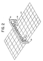
- the diffuser such as shown as 30 in Figure 2 is designed to have a number of holes that are preferably equally spaced and equal in diameter indicated by arrows 32. It is designed to cover the entire width of the furnace or at least the entire width of the conveyor belt used in the furnace 10.
- the diffuser device 30 can be made out of a steel pipe having a round, square, rectangular, triangular, or oval cross-section.
- the diffuser is designed to provide equal distribution of the flow of the oxidizing agent and carrier gas mixture through each hole and across the width of the furnace belt.
- the oxidizing agent and carrier gas mixture is dispensed as a series of jets through these holes.
- the diffuser or device 30 can be inserted into pre-heating zone 12 of furnace 10 through the side walls. It is placed close to the furnace ceiling.
- the holes 32 in the diffuser 30 can be pointed straight down toward the stainless steel mesh furnace belt 34. Preferably, they are pointed down with a small offset angle, e.g. between 10° and 15° from a vertical axis (perpendicular to the axis of the pipe). The offset angle is preferably oriented so that the holes or orifices face toward the entry end 24 of furnace 10.
- the oxidizing agent and carrier gas mixture can be introduced into one end 36 of diffuser 30 with the other end 38 of the diffuser capped or plugged.
- the diffuser is preferably fabricated from stainless steel.
- DDC diffuser design criterion
- the distance between holes it is desirable to select the distance between holes in such a way that the de-lubricating atmosphere introduced as a series of jets form a de-lubricating atmosphere curtain covering the entire width of the furnace or the entire width of the conveyor belt. It is preferable to select the distance between holes to provide some overlap of jets close to the compacts being treated in the furnace.
- the flow rate of the oxidant and carrier gas mixture (de-lubricating atmosphere) through a hole depends upon the momentum of jet required not only to penetrate streamlines of the main protective atmosphere flow but also to provide effective interaction between the oxidizing agent and lubricant vapours.
- the flow rate of the de-lubricating atmosphere through a hole also depends upon the strength of streamlines of the main protective atmosphere flow.
- the flow rate through a hole required to penetrate streamlines of main protective atmosphere flow and provide interaction with the lubricant vapours has to be increased with an increase in the main protective atmosphere flow rate. It can be calculated by knowing the strength of the main protective atmosphere flow through the preheating zone of the furnace. For example, it can be calculated from the momentum ratio R which is the ratio of the de-lubricating atmosphere jet momentum to the momentum of the main protective atmosphere flow. In order to penetrate streamlines of main protective atmosphere flow and provide interaction with the lubricant vapours, the value of momentum ratio should be above 50, preferably above 100, and more preferably above 125.
- de-lubricating atmosphere flow rate through a hole required to penetrate streamlines of the main protective atmosphere flow and provide interaction with the lubricant vapours has to be increased with increases in the height of the furnace.
- the total flow rate of de-lubricating atmosphere required can be calculated by multiplying the flow rate through a hole by the total number of holes in the diffuser. It is important to note that the flow rate through a hole in the diffuser should meet both the Reynolds number and momentum ratio requirements.
- the amount of an oxidizing agent added to the carrier gas depends on the total flow rate of the oxidant and carrier gas mixture employed. The amount is selected in such a way that it is high enough to accelerate lubricant removal, but not high enough to oxidize the surfaces of the compact. The right amount of an oxidant can be determined and selected by conducting a few de-lubricating trials.
- the oxidizing agent used to accelerate removal of lubricant can be selected from moisture, carbon dioxide, air or mixtures thereof.
- the amount of oxidizing agent added to the carrier gas depends on the total flow rate of the oxidizing agent and carrier gas stream mixture used. Specifically, a small amount of oxidizing agent is needed with high total flow rate and a large amount of oxidizing agent is needed with low total flow rate.
- moisture can be added by humidifying the carrier gas. It can also be added by reacting carrier gas containing a predetermined amount of oxygen with hydrogen in the presence of a precious metal catalyst.
- the amount or concentration of moisture in the total (moisture plus carrier gas) stream usually is at least 0.25 vol. % but at most 3 vol. %, preferably greater than 0.4 vol. %, more preferably greater than 0.6 vol. %, even more preferably greater than 1.0 vol. %.
- the amount or concentration of carbon dioxide in the total (carbon dioxide plus carrier gas) stream usually is at least 2 vol. % but at most 30 vol. %, preferably greater than 5 vol. %, more preferably greater than 10 vol. %, even more preferably greater than 15 vol. %.
- the amount or concentration of air in the total (air plus carrier gas) stream usually is at least 0.5 vol. % but at most 5 vol. %, preferably greater than 1 vol. %, more preferably greater than 2 vol. %, even more preferably greater than 3 vol. %.
- Metal powders that can be treated or de-lubricated according to the present invention include Fe and mixtures of Fe as the major component with a minor component selected from Cr, Ni, Mo, Co, Cu, Mn, V, W, C, B, Al, Si, P, S and mixtures thereof.
- the metal powder can be Fe-C with up to 1 wt. % carbon, Fe-Cu-C with up to 20 wt. % copper and 1 wt. % carbon, Fe-Ni with up to 50 wt. % nickel, Fe-Mo-Mn-Cu-Ni-C with up to 1 wt. % Mo, Mn, and carbon each and up to 2 wt.
- Ni and Cu each, and Fe-Cr-Mo-Co-Mn-V-W-C with varying concentrations of alloying elements depending upon the final properties of the sintered product desired.
- Other elements such as B, Al, Si, P, & S, can optionally be added to metal powders to obtain the desired properties in the final sintered product.
- These powders can be mixed with up to 2 wt. % lubricant to help in pressing components from them.
- the furnace had a 18" (45 cm) wide stainless steel mesh belt to transport test bars in and out of the furnace.
- test bars were pre-heated and de-lubricated in the pre-heating zone 12 and sintered in the high heating zone 14 of furnace 10 using a fixed belt speed and temperatures in the pre-heating 12 and high heating 14 zones of furnace 10. Likewise, a fixed time and temperature cycle was used in the high heating zone of the furnace to sinter test bars.
- the test bars were 0.25 inch (0.63 cm) high, 0.50 inch (1.27 cm) wide and 1.25 inch (3.18 cm) long. They were pressed to 6.8 g/cm 3 green density from Hoeganaes A1000 atomized iron powder.
- the powder was premixed with 0.75 wt. % zinc stearate as a lubricant and 0.9 wt. % graphite to provide a carbon level between 0.7 and 0.8 wt. % in the sintered bars.
- the belt was fully loaded with parts while conducting de-lubricating and sintering experiments.
- a protective atmosphere containing a blend of nitrogen, 3 vol. % hydrogen and 0.4 vol. % natural gas (main protective atmosphere stream) was introduced, as shown by arrow 19 into the furnace 10 through the transition zone 20 shown in Figure 1.
- the same main protective atmosphere composition was used in all the Examples.
- the total flow rate of the protective atmosphere used for sintering was 1,256 standard cubic feet per hour ("SCFH") (35.57 standard cubic meters per hour (“SCMH”)) or 1,456 SCFH (41.23 SCMH).
- a de-lubricating atmosphere consisting of a nitrogen stream alone or mixed with moisture, carbon dioxide or air was introduced into the pre-heating zone 12 of the furnace 10 to assist in removing lubricant from powder metal test bars.
- the de-lubricating atmosphere was introduced into the pre-heating zone 12 of furnace 10 using either an improperly designed diffuser or a properly designed diffuser. This atmosphere was introduced into the preheating zone 12 of furnace 10 at a distance of about 9 feet (2.75 m) from the beginning of feed vestibule 26, as shown in Figure 1.
- the de-lubricating atmosphere was introduced at a point, as shown by arrow 22, in the pre-heating zone 12 where the temperature of test bars has reached 1400°F (760°C), as revealed by the temperature profile in the furnace shown by the plot of Figure 3.
- the total flow rate of the de-lubricating atmosphere was varied between 80 SCFH (2.25 SCMH) and 350 SCFH (9.9 SCMH).
- the moisture in the de-lubricating atmosphere was introduced by passing nitrogen through a humidifier (bubbler), or by blending nitrogen with controlled amounts of hydrogen and air and producing moisture by reacting the oxygen present in the air and hydrogen in the presence of a precious metal catalyst.
- the moisture level in the de-lubricating atmosphere was varied from 0.4 to 4.5 volume %.
- Carbon dioxide or air in the de-lubricating atmosphere was introduced simply by blending nitrogen with carbon dioxide or air.
- the concentration of carbon dioxide in de-lubricating atmosphere was varied from 5 to 80 volume %.
- the concentration of air in the de-lubricating atmosphere was varied from 1.25 to 26.6 volume %.
- the improperly designed diffuser was fabricated from a 1 inch (2.54 cm) diameter pipe. It contained sixteen 1/4 inch (0.63 cm) diameter holes that were equally spaced. These sixteen holes covered the entire width of the stainless steel belt. This improperly designed diffuser was already in the furnace, and was used on a daily basis. A quick design review of this diffuser revealed that it was not designed to provide uniform de-lubricating atmosphere flow through all sixteen holes. The value of DDC for this diffuser was calculated to be 1.0, which is significantly less than the minimum value of 1.4 recommended as an acceptable diffuser design criterion.
- a properly designed diffuser 30, as shown in Figure 2 was fabricated from a 1/2 inch (1.27 cm) stainless steel tube.
- Diffuser 30 contained twenty-two 1/16 inch (0.16 cm) diameter holes 32 that were equally spaced. The twenty-two holes 32 covered the entire width of the stainless steel belt 34. Holes 32 in the diffuser or device 30 were pointed down with a 15° off-set angle to a vertical line perpendicular to the belt 34 and with the holes pointed or oriented toward the front or entry end 24 of furnace 10. The value of DDC for this diffuser was calculated to be - 1.7, which met the diffuser design criteria.
- the de-lubricated and sintered test bars were evaluated for surface appearance, weight and dimensional changes, and apparent hardness of top and bottom surfaces. A few select test bars were evaluated metallographically and tested for transverse rupture strength. The effectiveness of an oxidant for removing lubricant was judged by a combination of surface appearance, apparent surface hardness and strength of the de-lubricated and sintered bars.
- a de-lubricating followed by sintering experiment was carried out in the continuous furnace described above. This experiment was carried out by introducing 1,456 SCFH (41.23 SCMH) of the main protective atmosphere containing nitrogen, 3 vol. % hydrogen and 0.4 vol. % natural gas into the furnace through the transition zone, as described earlier. No other gas including de-lubricating atmosphere was used in this experiment.
- the furnace was operated using the same parameters, including operating temperature and belt speed, as described earlier.
- a number of transverse rupture strength test bars described earlier were processed along with a full load of parts in the furnace.
- test bars sintered in this experiment were heavily covered with undesirable soot and dark residue, indicating improper removal of lubricant from the test bars in the preheating zone of the furnace.
- the results of this experiment confirmed that a de-lubricating atmosphere is needed to remove lubricant or sweep away lubricant vapours in the preheating zone of the furnace and avoid the formation of soot and residue.
- a de-lubricating followed by sintering experiment described in Example 1 was repeated by introducing 1,456 SCFH (41.23 SCMH) of the main protective atmosphere containing nitrogen, 3 vol. % hydrogen and 0.4 vol. % natural gas into the furnace through the transition zone 20.
- a de-lubricating atmosphere containing 80 SCFH (2.25 SCMH) of pure nitrogen was introduced into the preheating zone of the furnace through an improperly designed diffuser.
- the Reynolds number of the de-lubricating atmosphere introduced through the holes in the diffuser was ⁇ 490 and the value of momentum ratio was ⁇ 5, both of which did not meet the de-lubricating atmosphere flow introduction parameters specified earlier in the main body of the text.
- the design and location of an improperly designed diffuser were same as described earlier.
- the furnace was operated using the same operating parameters, including operating temperature and belt speed, as described earlier.
- a number of transverse rupture strength test bars described earlier were processed along with a full load of parts in the furnace.
- test bars sintered in this experiment were heavily covered with undesirable soot and dark residue, indicating improper removal of lubricant from the test bars in the preheating zone of the furnace.
- the results of this experiment showed that a low flow rate of a de-lubricating atmosphere containing no oxidant and the de-lubricating atmosphere introduced through an improperly designed diffuser are not good enough to remove or sweep lubricant vapours away from the surface of compacts in the preheating zone of the furnace and avoid the formation of soot and residue on the surface of compacts.
- Example 2A A de-lubricating followed by sintering experiment described in Example 2A was repeated using similar conditions with the exception of using 200 SCFH (5.66 SCMH) de-lubricating atmosphere containing pure nitrogen.
- the Reynolds number of the de-lubricating atmosphere introduced through the holes in the diffuser was -1,230 and the value of momentum ratio was -12, both of which did not meet the de-lubricating atmosphere flow introduction parameters specified earlier in the main body of the text.
- the furnace was operated using the same operating parameters, including operating temperature and belt speed, as described earlier. A number of transverse rupture strength test bars described earlier were processed along with a full load of parts in the furnace.
- test bars sintered in this experiment were heavily covered with undesirable soot and dark residue, indicating improper removal of lubricant from the test bars in the preheating zone of the furnace.
- the results of this experiment showed that a high flow rate of a de-lubricating atmosphere containing no oxidant and the de-lubricating atmosphere introduced through an improperly designed diffuser are not good enough to remove or sweep lubricant vapours away from the surface of compacts in the preheating zone of the furnace and avoid the formation of soot and residue on the surface of compacts.
- a de-lubricating followed by sintering experiment described in Example 1 was repeated by introducing 1,256 SCFH (35.57 SCMH) of the main protective atmosphere containing nitrogen, 3 vol. % hydrogen and 0.4 vol. % natural gas into the furnace 10 through the transition zone 20.
- a de-lubricating atmosphere containing 100 SCFH (2.83 SCMH) of pure nitrogen was introduced into the preheating zone 12 of the furnace 10 through a properly designed diffuser.
- the design and location of a properly designed diffuser were same as described above.
- the Reynolds number of the de-lubricating atmosphere introduced through the holes in the diffuser was ⁇ 1,790 and the value of momentum ratio was ⁇ 84.
- the de-lubricating atmosphere flow introduction parameter Reynolds number did not meet the minimum value specified earlier in the main body of the text.
- the furnace was operated using the same operating parameters, including operating temperature and belt speed, as described earlier. A number of transverse rupture strength test bars described earlier were processed along with a full load of parts in the furnace.
- test bars sintered in this experiment were heavily covered with undesirable soot and dark residue, indicating improper removal of lubricant from the test bars in the preheating zone of the furnace.
- the results of this experiment showed that a low flow of a de-lubricating atmosphere containing no oxidant is not good enough to remove or sweep lubricant vapours away from the surface of compacts in the preheating zone of the furnace and avoid the formation of soot and residue on the surface of compacts.
- a de-lubricating followed by sintering experiment such as described in Example 2C was repeated using similar conditions with the exception of using 200 SCFH (5.66 SCMH) de-lubricating atmosphere containing pure nitrogen.
- the Reynolds number of the de-lubricating atmosphere introduced through the holes in the diffuser was -3,580 and the value of momentum ratio was -165.
- the furnace was operated using the same operating parameters, including operating temperature and belt speed, as described earlier. A number of transverse rupture strength test bars described earlier were processed along with a full load of parts in the furnace.
- test bars sintered in this experiment were heavily covered with undesirable soot and dark residue, indicating improper removal of lubricant from the test bars in the preheating zone of the furnace.
- the results of this experiment showed that a high flow rate of a de-lubricating atmosphere containing no oxidant is not good enough to remove or sweep lubricant vapours away from the surface of compacts in the preheating zone of the furnace and avoid the formation of soot and residue on the surface of compacts.
- the results showed that a de-lubricating atmosphere containing no oxidant is not effective in removing lubricant even if it is introduced through a properly designed diffuser and using the right de-lubricating atmosphere flow introduction parameters.
- a de-lubricating followed by a sintering experiment such as described in Example 2A was repeated by introducing 1,456 SCFH (41.23 SCMH) of the main protective atmosphere containing nitrogen, 3 vol. % hydrogen and 0.4 vol. % natural gas into the furnace through the transition zone.
- a de-lubricating atmosphere containing 80 SCFH (2.25 SCMH) of nitrogen mixed with moisture was introduced into the preheating zone of the furnace through an improperly designed diffuser.
- the concentration of moisture in the de-lubricating gas was very high; about 4.5% by volume.
- the design and location of an improperly designed diffuser were same as described earlier.
- the Reynolds number of the de-lubricating atmosphere introduced through the holes in the diffuser was -490 and the value of momentum ratio was ⁇ 5, both of which did not meet the de-lubricating atmosphere flow introduction parameters specified above.
- the furnace was operated using the same operating parameters, including operating temperature and belt speed, as described earlier. A number of transverse rupture strength test bars described earlier were processed along with a full load of parts in the furnace.
- test bars sintered in this experiment were covered with undesirable soot and dark residue, indicating incomplete removal of lubricant from the test bars in the preheating zone of the furnace.
- the results of this experiment showed that a low flow rate of a de-lubricating atmosphere containing high concentration of an oxidant and the de-lubricating atmosphere introduced through an improperly designed diffuser with incorrect de-lubricating atmosphere introduction parameters are not good enough to remove lubricant from the surface of compacts in the preheating zone of the furnace and avoid the formation of soot and residue on the surface of compacts.
- a de-lubricating followed by a sintering experiment such as described in Example 3A was repeated using similar conditions with the exception of using 200 SCFH (5.66 SCMH) de-lubricating atmosphere containing nitrogen and 4.5 vol. % moisture.
- the Reynolds number of the de-lubricating atmosphere introduced through the holes in the diffuser was ⁇ 1,230 and the value of momentum ratio was ⁇ 12, both of which did not meet the de-lubricating atmosphere flow introduction parameters specified above.
- the furnace was operated using the same operating parameters including, operating temperature and belt speed, as described earlier. A number of transverse rupture strength test bars described earlier were processed along with a full load of parts in the furnace.
- test bars sintered in this experiment were heavily covered with undesirable soot and dark residue, indicating improper removal of lubricant from the test bars in the preheating zone of the furnace.
- the results of this experiment showed that a high flow rate of a de-lubricating atmosphere containing high concentration of an oxidant and the de-lubricating atmosphere introduced through an improperly designed diffuser with incorrect de-lubricating atmosphere introduction parameters are not good enough to remove lubricant from the surface of compacts in the preheating zone of the furnace and avoid the formation of soot and residue on the surface of compacts.
- a number of de-lubricating followed by sintering experiments similar to the one described in Example 2A were carried out by introducing 1,256 SCFH (35.57 SCMH) of the main protective atmosphere containing nitrogen, 3 vol. % hydrogen and 0.4 vol. % natural gas into the furnace through the transition zone.
- a de-lubricating atmosphere containing 75 SCFH (2.12 SCMH) of nitrogen mixed with moisture as an oxidant was introduced into the preheating zone of the furnace through a properly designed diffuser.
- the moisture content in the de-lubricating atmosphere used in these experiment was selected from 0.4, 1.0, 2.0 and 3.0% by volume.
- the design and location of a properly designed diffuser were same as described earlier.
- the Reynolds number of the de-lubricating atmosphere introduced through the holes in the diffuser was ⁇ 1,345 and the value of momentum ratio was ⁇ 63.
- the de-lubricating atmosphere flow introduction parameter Reynolds number did not meet the minimum value specified above.
- the furnace was operated using the same operating parameters, including operating temperature and belt speed, as described earlier. A number of transverse rupture strength test bars described earlier were processed along with a full load of parts in the furnace.
- test bars sintered with 0.4 vol. % moisture in the de-lubricating atmosphere were covered heavily with undesirable soot and dark residue, indicating improper removal of lubricant from the test bars in the preheating zone of the furnace.
- the presence of soot and dark residue on the surface of sintered test bars decreased somewhat with increasing moisture content in the de-lubricating atmosphere.
- the test bars sintered in the presence of a high moisture content (3 vol. % moisture) in the de-lubricating atmosphere were still covered with soot and dark residue.
- the results of these experiment indicated that a considerably higher than 3 vol. % moisture in the de-lubricating atmosphere would be needed to significantly improve removal of lubricant from compacts in the preheating zone of a sintering furnace.
- it is not practical to use more than 3 vol. % moisture in the de-lubricating atmosphere because moisture would start condensing in the transfer line.
- a number of de-lubricating followed by sintering experiments similar to the one described in Example 4A were carried out by introducing 1,256 SCFH (35.57 SCMH) of the main protective atmosphere containing nitrogen, 3 vol. % hydrogen and 0.4 vol. % natural gas into the furnace through the transition zone.
- a de-lubricating atmosphere containing 75 SCFH (2.12 SCMH) of nitrogen mixed with carbon dioxide as an oxidant was introduced into the preheating zone of the furnace through a properly designed diffuser.
- the amount of carbon dioxide in the de-lubricating atmosphere used in these experiments was selected from 13.33, 33.33, 53.33, 66.67, and 80% by volume.
- the design and location of a properly designed diffuser were same as described earlier.
- the Reynolds number of the de-lubricating atmosphere introduced through the holes in the diffuser was -1,345 and the value of momentum ratio was ⁇ 63.
- the de-lubricating atmosphere flow introduction parameter Reynolds number did not meet the minimum value specified above.
- the furnace was operated using the same operating parameters, including operating temperature and belt speed, as described earlier. A number of transverse rupture strength test bars described earlier were processed along with a full load of parts in the furnace.
- test bars sintered with 13.33 vol. % carbon dioxide in the de-lubricating atmosphere were covered heavily with undesirable soot and dark residue, indicating improper removal of lubricant from the test bars in the preheating zone of the furnace.
- the presence of soot and dark residue on the surface of sintered test bars decreased somewhat with increasing the amount of carbon dioxide in the de-lubricating atmosphere.
- the test bars sintered in the presence of very high amount of carbon dioxide (80 vol. % carbon dioxide) in the de-lubricating atmosphere were still covered with soot and dark residue. The results of these experiment indicated that a considerably higher amount of carbon dioxide than 80 vol. % in the de-lubricating atmosphere would be needed to significantly improve removal of lubricant from compacts in the preheating zone of a sintering furnace.
- a number of de-lubricating followed by sintering experiments similar to the one described in Example 4A were carried out by introducing 1,256 SCFH (35.57 SCMH) of the main protective atmosphere containing nitrogen, 3 vol. % hydrogen and 0.4 vol. % natural gas into the furnace through the transition zone.
- a de-lubricating atmosphere containing 75 SCFH (2.12 SCMH) of nitrogen mixed with air as an oxidant was introduced into the preheating zone of the furnace through a properly designed diffuser.
- the concentration of air in the de-lubricating atmosphere used in these experiment was selected from 3.33, 6.66, 10.0, and 26.64% by volume.
- the design and location of a properly designed diffuser were same as described earlier.
- the Reynolds number of the de-lubricating atmosphere introduced through the holes in the diffuser was ⁇ 1345 and the value of momentum ratio was ⁇ 63.
- the de-lubricating atmosphere flow introduction parameter Reynolds number did not meet the minimum value specified above.
- the furnace was operated using the same operating parameters, including operating temperature and belt speed, as described earlier. A number of transverse rupture strength test bars described earlier were processed along with a full load of parts in the furnace.
- test bars sintered with 3.33 vol. % air in the de-lubricating atmosphere were covered heavily with undesirable soot and dark residue, indicating improper removal of lubricant from the test bars in the preheating zone of the furnace.
- the presence of soot and dark residue on the surface of sintered test bars decreased somewhat with increasing the amount of air in the de-lubricating atmosphere.
- the test bars sintered in the presence of de-lubricating atmosphere containing 10 vol. % air were still covered with soot and dark residue. More importantly, there was no soot or dark residue present on the surface of bars sintered in the presence of a de-lubricating atmosphere containing 26.64 vol. % air. However, the use of 26.64 vol.
- Examples 4A to 4C showed that the use of low flow rate of de-lubricating atmosphere containing high concentrations of an oxidant is not effective in removing lubricant from powder metal compacts in the preheating zone of a sintering furnace. This is true even if a properly designed diffuser with incorrect de-lubricating atmosphere introduction parameters is used to introduce de-lubricating atmosphere in the preheating zone of the furnace.
- the data also showed that a high concentration of air in the de-lubricating atmosphere can be used to effectively remove lubricant from powder metal compacts, but at the expense of oxidizing surface of sintered components.
- the distribution of fluid flow in the preheating zone of the sintering furnace was simulated using a well known computational fluid dynamics software package to explain the reasons of improper lubricant removal even with the use of a high concentration of an oxidant in the de-lubricating atmosphere.
- the computer simulation showed that the main flow of the atmosphere in the preheating zone of the furnace follows a streamline pattern. It also showed that when a low flow rate of a de-lubricating atmosphere is introduced as a series of jets through a properly designed diffuser, the jets do not have enough momentum to penetrate the streamline flow pattern of the main atmosphere flow as shown in the flow distribution diagram of Figure 4.
- the de-lubricating atmosphere containing an oxidant does not get a chance to interact with lubricant vapours diffusing out of the surface of powder metal compacts and effectively remove lubricant vapours by decomposing them to smaller and more volatile components.
- the de-lubricating atmosphere eventually mixes with the main atmosphere flow, but by that time the concentration of an oxidant in the total stream has become very small to be effective in removing lubricant from powder metal compacts.
- the Reynolds number of the de-lubricating atmosphere introduced through the holes in the diffuser was -3,585 and the value of momentum ratio was -167, both of which met the minimum de-lubricating atmosphere flow introduction parameters specified earlier in the main body of the text.
- the furnace was operated using the same operating parameters, including operating temperature and belt speed, as described earlier. A number of transverse rupture strength test bars described earlier were processed along with a full load of parts in the furnace.
- test bars sintered with 0.4 vol. % moisture in the de-lubricating atmosphere were covered slightly with undesirable soot and dark residue, indicating improper removal of lubricant from the test bars in the preheating zone of the furnace.
- the test bars on the average showed close to 0.25% growth in linear dimensions that was well within the limits specified by the powder supplier.
- the apparent surface hardness of sintered bars varied between 61 to 66 HRB that was also well within the range specified by the powder supplier.
- the transverse rupture strength of sintered bars was close to 90,000 psi (620 MPa) which was also within the range specified by the powder supplier.
- the bulk carbon content in the sintered bars was between 0.7 to 0.8% by weight.
- Cross-sectional analysis of the bars revealed no surface decarburization.
- the results of these experiment clearly showed that a de-lubricating atmosphere containing more than 0.4 vol. % moisture can be effectively used to de-lubricate powder metal compacts in the preheating zone of a sintering furnace if introduced through a properly designed diffuser using the proper de-lubricating atmosphere introduction parameters.
- a number of de-lubricating followed by sintering experiments similar to the one described in Example 5A were carried out by introducing 1,256 SCFH (35.57 SCMH) of the main protective atmosphere containing nitrogen, 3 vol. % hydrogen and 0.4 vol. % natural gas into the furnace through the transition zone.
- a de-lubricating atmosphere containing 200 SCFH (5.66 SCMH) of nitrogen mixed with carbon dioxide as an oxidant was introduced into the preheating zone of the furnace through a properly designed diffuser.
- the concentration of carbon dioxide in the de-lubricating atmosphere used in these experiment was selected from 5, 10, 15, 20, 25 and 30% by volume.
- the design and location of a properly designed diffuser were same as described earlier.
- the Reynolds number of the de-lubricating atmosphere introduced through the holes in the diffuser was ⁇ 3,585 and the value of momentum ratio was ⁇ 167, both of which met the minimum de-lubricating atmosphere flow introduction parameters specified earlier in the main body of the text.
- the furnace was operated using the same operating parameters, including operating temperature and belt speed, as described earlier. A number of transverse rupture strength test bars described earlier were processed along with a full load of parts in the furnace.
- test bars sintered with 10 vol. % carbon dioxide or less in the de-lubricating atmosphere were covered lightly with undesirable soot and dark residue, indicating improper removal of lubricant from the test bars in the preheating zone of the furnace.
- the test bars on the average showed close to 0.24% growth in linear dimensions that was well within the limits specified by the powder supplier.
- the apparent surface hardness of sintered bars varied between 62 to 67 HRB that was also well within the range specified by the powder supplier.
- the transverse rupture strength of sintered bars was close to 95,000 psi (655 MPa) which was also within the range specified by the powder supplier.
- the bulk carbon content in the sintered bars was between 0.7 to 0.8% by weight.
- Cross-sectional analysis of the bars revealed no surface decarburization. The results of these experiment clearly showed that a de-lubricating atmosphere containing more than 10 vol. % carbon dioxide can be effectively used to de-lubricate powder metal compacts in the preheating zone of a sintering furnace if introduced through a properly designed diffuser using the proper de-lubricating atmosphere introduction parameters.
- a number of de-lubricating followed by sintering experiments similar to the one described in Example 5A were carried out by introducing 1,256 SCFH (35.57 SCMH) of the main protective atmosphere containing nitrogen, 3 vol. % hydrogen and 0.4 vol. % natural gas into the furnace through the transition zone.
- a de-lubricating atmosphere containing 200 SCFH (5.66 SCMH) of nitrogen mixed with air as an oxidant was introduced into the preheating zone of the furnace through a properly designed diffuser.
- the concentration of air in the de-lubricating atmosphere used in these experiment was 1.25, 2.50, 3.33, 3.75, and 5.0% by volume.
- the design and location of a properly designed diffuser were same as described earlier.
- the Reynolds number of the de-lubricating atmosphere introduced through the holes in the diffuser was -3,585 and the value of momentum ratio was ⁇ 167, both of which met the minimum de-lubricating atmosphere flow introduction parameters specified earlier in the main body of the text.
- the furnace was operated using the same operating parameters, including operating temperature and belt speed, as described earlier. A number of transverse rupture strength test bars described earlier were processed along with a full load of parts in the furnace.
- test bars sintered with 2.5 vol. % air or less in the de-lubricating atmosphere were covered heavily with undesirable soot and dark residue, indicating improper removal of lubricant from the test bars in the preheating zone of the furnace.
- the surface of bars processed in the presence of a de-lubricating atmosphere containing 5 vol. % air were oxidized in the pre-heating zone and produced an unacceptable frosted surface finish after sintering in the high heating zone of the furnace.
- the results of these experiment indicated that air can be effectively used to remove lubricant in the preheating zone of the furnace, but one has to be extremely careful in selecting the right concentration of air in the de-lubricating atmosphere.
- Examples 5A to 5C showed that the use of a high flow rate of de-lubricating atmosphere containing an oxidant above certain specified concentration is very effective in removing lubricant from powder metal compacts in the preheating zone of a sintering furnace. These examples also showed that it is extremely important to satisfy all the design parameters specified earlier for designing a diffuser and selecting the de-lubricating atmosphere flow to effectively remove lubricants from the powder metal compacts. The data also showed that air can be used as an oxidant in the de-lubricating atmosphere for effectively removing lubricant from powder metal compacts, but one has to be extremely careful in selecting the right concentration of air in the de-lubricating atmosphere.
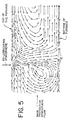
- the distribution of fluid flow in the preheating zone of the sintering furnace was simulated with a computer using a well known computational fluid dynamics software package to explain the reasons of proper lubricant removal.
- the computer simulation showed that when a high flow rate of a de-lubricating atmosphere is introduced as a series of jets through a properly designed diffuser-user, the jets have enough momentum to penetrate the streamline flow pattern of the main atmosphere flow, as shown in the flow distribution diagram of Figure 5. Consequently, the de-lubricating atmosphere containing an oxidant has ample opportunity to interact with the surface of powder metal compacts and effectively remove lubricant vapours by decomposing them to smaller and more volatile components.
- a number of de-lubricating followed by sintering experiments similar to the one described in Example 5B were carried out by introducing 1,256 SCFH (35.57 SCMH) of the main protective atmosphere containing nitrogen, 3 vol. % hydrogen and 0.4 vol. % natural gas into the furnace through the transition zone.
- a de-lubricating atmosphere containing 350 SCFH (9.9 SCMH) of nitrogen mixed with carbon dioxide as an oxidant was introduced into the preheating zone of the furnace through a properly designed diffuser.
- the concentration of carbon dioxide in the de-lubricating gas used in these experiment was selected from 2.85, 7.14, and 11.43% by volume.
- the design and location of a properly designed diffuser were same as described earlier.
- the Reynolds number of the de-lubricating atmosphere introduced through the holes in the diffuser was ⁇ 6,275 and the value of momentum ratio was ⁇ 295, both of which met the minimum de-lubricating atmosphere flow introduction parameters specified earlier in the main body of the text.
- the furnace was operated using the same operating parameters, including operating temperature and belt speed, as described earlier. A number of transverse rupture strength test bars described earlier were processed along with a full load of parts in the furnace.
- test bars sintered in these experiments were free from undesirable soot and dark residue, indicating proper removal of lubricant from the test bars in the preheating zone of the furnace.
- the results of these experiment clearly showed that the concentration of an oxidant needed for effectively removing lubricant from powder metal compacts can be reduced by using a high flow rate of de-lubricating atmosphere.
- a number of de-lubricating followed by sintering experiments similar to the one described in Example 5C were carried out by introducing 1,256 SCFH (35.57 SCMH) of the main protective atmosphere containing nitrogen, 3 vol. % hydrogen and 0.4 vol. % natural gas into the furnace through the transition zone.
- a de-lubricating atmosphere containing 350 SCFH (9.9 SCMH) of nitrogen mixed with air as an oxidant was introduced into the preheating zone of the furnace through a properly designed diffuser.
- the concentration of air in the de-lubricating gas used in these experiments was selected from 0.7 and 1.4% by volume.
- the design and location of a properly designed diffuser were same as described earlier.
- the Reynolds number of the de-lubricating atmosphere introduced through the holes in the diffuser was ⁇ 6,275 and the value of momentum ratio was ⁇ 295, both of which met the minimum de-lubricating atmosphere flow introduction parameters specified earlier in the main body of the text.
- the furnace was operated using the same operating parameters, including operating temperature and belt speed, as described earlier. A number of transverse rupture strength test bars described earlier were processed along with a full load of parts in the furnace.
- test bars sintered in these experiments were free from undesirable soot and dark residue, indicating proper removal of lubricant from the test bars in the preheating zone of the furnace.
- the results of these experiments clearly showed that the concentration of an oxidant needed for effectively removing lubricant from powder metal compacts could be reduced by using a high flow rate of de-lubricating atmosphere.
- a number of de-lubricating followed by sintering experiments similar to the one described in Example 5A are carried out by introducing 1,256 SCFH (35.57 SCMH) of the main protective atmosphere containing nitrogen, 3 vol. % hydrogen and 0.4 vol. % natural gas into the furnace through the transition zone.
- a de-lubricating atmosphere containing 350 SCFH (9.9 SCMH) of nitrogen mixed with moisture as an oxidant is introduced into the preheating zone of the furnace through a properly designed diffuser.
- the concentration of moisture in the de-lubricating gas used in these experiments is selected from 0.25, 0.5, and 1.0% by volume.
- the design and location of a properly designed diffuser are same as described earlier.
- the Reynolds number of the de-lubricating atmosphere introduced through the holes in the diffuser is ⁇ 6.275 and the value of momentum ratio is ⁇ 295, both of which meet the minimum de-lubricating atmosphere flow introduction parameters specified earlier in the main body of the text.
- the furnace is operated using the same operating parameters, including operating temperature and belt speed, as described earlier. A number of transverse rupture strength test bars described earlier are processed along with a full load of parts in the furnace.
- test bars sintered in these experiments are free from undesirable soot and dark residue, indicating proper removal of lubricant from the test bars in the preheating zone of the furnace.
- the results of these experiments clearly show that the concentration of an oxidant needed for effectively removing lubricant from powder metal compacts can be reduced by using a high flow rate of de-lubricating atmosphere.
- a number of de-lubricating followed by sintering experiments similar to the one described in Example 5A are carried out by introducing 1,256 SCFH (35.57 SCMH) of the main protective atmosphere containing nitrogen, 3 vol. % hydrogen and 0.4 vol. % natural gas into the furnace through the transition zone.
- a de-lubricating atmosphere containing 150 SCFH (4.25 SCMH) of nitrogen mixed with moisture as an oxidant is introduced into the preheating zone of the furnace through a properly designed diffuser.
- the concentration of moisture in the de-lubricating gas used in these experiments is selected from 1.0, 1.5. and 2.0% by volume.
- the design and location of a properly designed diffuser are same as described earlier.
- the Reynolds number of the de-lubricating atmosphere introduced through the holes in the diffuser is ⁇ 2,690 and the value of momentum ratio is ⁇ 125, both of which meet the minimum de-lubricating atmosphere flow introduction parameters specified earlier in the main body of the text.
- the furnace is operated using, the same operating parameters, including operating temperature and belt speed, as described earlier. A number of transverse rupture strength test bars described earlier are processed along with a full load of parts in the furnace.
- test bars sintered in these experiments are free from undesirable soot and dark residue, indicating proper removal of lubricant from the test bars in the preheating zone of the furnace.
- the results of these experiments clearly show that the concentration of an oxidant required for effectively removing lubricant from powder metal compacts needs to be increased by using a medium flow rate of de-lubricating atmosphere.
- a number of de-lubricating followed by sintering experiments similar to the one described in Example 5B are carried out by introducing 1,256 SCFH (35.57 SCMH) of the main protective atmosphere containing nitrogen, 3 vol. % hydrogen and 0.4 vol. % natural gas into the furnace through the transition zone.
- a de-lubricating atmosphere containing 150 SCFH (4.25 SCMH) of nitrogen mixed with carbon dioxide as an oxidant is introduced into the preheating zone of the furnace through a properly designed diffuser.
- the concentration of carbon dioxide in the de-lubricating gas used in these experiments is selected from 15, 20, and 25% by volume.
- the design and location of a properly designed diffuser are same as described earlier.
- the Reynolds number of the de-lubricating atmosphere introduced through the holes in the diffuser is ⁇ 2,690 and the value of momentum ratio is ⁇ 125, both of which meet the minimum de-lubricating atmosphere flow introduction parameters specified earlier in the main body of the text.
- the furnace is operated using the same operating parameters, including operating temperature and belt speed, as described earlier. A number of transverse rupture strength test bars described earlier are processed along with a full load of parts in the furnace.
- test bars sintered in these experiments are free from undesirable soot and dark residue, indicating proper removal of lubricant from the test bars in the preheating zone of the furnace.
- the results of these experiments clearly show that the concentration of an oxidant required for effectively removing lubricant from powder metal compacts needs to be increased by using a medium flow rate of de-lubricating atmosphere.
- a number of de-lubricating followed by sintering experiment similar to the one described in Example 5A are carried out by introducing 1,256 SCFH (35.57 SCMH) of the main protective atmosphere containing nitrogen, 3 vol. % hydrogen and 0.4 vol. % natural gas into the furnace through the transition zone.
- a de-lubricating atmosphere containing 150 SCFH (4.25 SCMH) of nitrogen mixed with air as an oxidant is introduced into the preheating zone of the furnace through a properly designed diffuser.
- the concentration of air in the de-lubricating gas used in these experiments is selected from 2.0, 3.0, and 4.0% by volume.
- the design and location of a properly designed diffuser are same as described earlier.
- the Reynolds number of the de-lubricating atmosphere introduced through the holes in the diffuser is ⁇ 2,690 and the value of momentum ratio is ⁇ 125, both of which meet the minimum de-lubricating atmosphere flow introduction parameters specified earlier in the main body of the text.
- the furnace is operated using the same operating parameters, including operating temperature and belt speed, as described earlier. A number of transverse rupture strength test bars described earlier are processed along with a full load of parts in the furnace.
- test bars sintered in these experiments are free from undesirable soot and dark residue, indicating proper removal of lubricant from the test bars in the preheat zone of the furnace.
- the results of these experiments clearly show that the concentration of an oxidant required for effectively removing lubricant from powder metal compacts needs to be increased by using a medium flow rate of de-lubricating atmosphere.
- the above Examples show that the concentration of an oxidant needed for effectively removing lubricant from powder metal compacts depends upon the flow rate of the de-lubricating atmosphere.
- the results also show that one can use a low concentration of an oxidant with a high flow rate of de-lubricating atmosphere or a high concentration of an oxidant with a low flow rate of de-lubricating atmosphere to effectively remove lubricant from the powder metal compacts in the preheating zone of a continuous sintering furnace provided a properly designed diffuser is used to introduce de-lubricating atmosphere and the de-lubricating atmosphere introduction parameters are satisfied.
- the concentration of an oxidant in the de-lubricating atmosphere and the total flow rate of a de-lubricating atmosphere must be above certain minimum value to be effective in (1) penetrating streamlines of main atmosphere flow, (2) interacting with the surface of powder metal compacts, and (3) removing lubricant from powder metal compacts in the preheating zone of a sintering furnace.
- This right combination of the de-lubricating atmosphere flow rate and the concentration of an oxidant depends on the furnace geometry such as width and height, and can be determined by conducting a few trials.
- While a single diffuser has been shown to be effective, it is within the scope of the present invention to use more than one and possibly multiple diffusers placed between the entry end of the pre-heat zone of the furnace and a location in the pre-heat zone or section of the furnace where the parts to be treated have reached a temperature of about 1450°F (790°C). It is also within the scope of the present invention to have more than one row of holes or apertures in a single diffuser.
Landscapes
- Engineering & Computer Science (AREA)
- Mechanical Engineering (AREA)
- General Engineering & Computer Science (AREA)
- Manufacturing & Machinery (AREA)
- Chemical & Material Sciences (AREA)
- Materials Engineering (AREA)
- Metallurgy (AREA)
- Organic Chemistry (AREA)
- Powder Metallurgy (AREA)
- Lubricants (AREA)
- Manufacture And Refinement Of Metals (AREA)
Claims (24)
- Verfahren zum Entfernen von Schmiermitteln aus Pulvermetall-Presskörpern bzw. Pressteilen, die ein Schmiermittel enthalten, das dazu verwendet wird, die Pulvermetall-Presskörper zu bilden, mit den Schritten der Vorwärmung der Pulvermetall-Presskörper auf eine Temperatur von wenigstens 200° C (400° F) unter einer Schutzatmosphäre und während des Vorwärmens, Einführung einer Schmiermittel entfernenden bzw. abrauchenden Atmosphäre aus einem Trägergas mit einem Oxidationsmittel, das aus Luft, Wasserdampf, Kohlendioxid und ihren Gemischen ausgewählt wird, dadurch gekennzeichnet, dass die Schmiermittel entfernende Atmosphäre eingeführt wird, wenn die Presskörper eine Temperatur von 200° C (400° F) bis 820° C (1500° F) erreicht haben, und die Oberfläche der Presskörper durch Eindringen durch die Schutzatmosphäre berührt, um eine Wechselwirkung zwischen dem Oxidationsmittel und den Schmiermittel-Dämpfen an den Oberflächen ohne Oxidation der Oberfläche zur Verfügung zu stellen.
- Verfahren nach Anspruch 1, wobei die Schutzatmosphäre während des Vorwärmens über die Presskörper strömt und die die Schmiermittel entfernende Atmosphäre mit ausreichendem Impuls bzw. Antriebskraft zugeführt wird, um die Stromlinien der Schutzatmosphäre zu durchdringen.
- Verfahren nach Anspruch 2, wobei die Vorwärmung in einer Vorwärmzone eines kontinuierlichen Sinterofens mit der Vorwärmzone und einer Hochtemperatur-Sinterzone durchgeführt wird, durch die sich die Presskörper in Folge bewegen, und wobei die Vorwärm- und Sinterzonen unter einer Schutzatmosphäre gehalten werden und die Schmiermittel entfernende Atmosphäre als eine Gasströmung quer zur Bewegung der Pulver-Presskörper durch den Ofen eingeführt wird.
- Verfahren nach Anspruch 2 oder Anspruch 3, wobei die Schmiermittel entfernende Atmosphäre als eine Serie von Strahlen zugeführt wird.
- Verfahren nach Anspruch 4, wobei die Schmiermittel entfernende Atmosphäre in einem Betriebszustand turbulenter Strömung durch eine Vielzahl von Öffnungen in einer Leitung zugeführt wird, die sich quer zur Strömungsrichtung der Schutzatmosphäre erstreckt und Diffoser-Design-Kriterien von wenigstens 1,4 hat, wobei die Duffusor-Design-Kriterien (DDC für diffuser design criteria) entsprechend der Gleichung bestimmt werden:D ist der Durchmesser der, oder der Äquivalenz-Durchmesser, wenn sie keinen kreisförmigen Querschnitt hat, der Leitung,d ist der Durchmesser der Öffnungen, undN ist die Gesamtzahl der Öffnungen.
- Verfahren nach Anspruch 5, wobei die Duffusor-Design-Kriterien wenigstens 1,5 sind.
- Verfahren nach einem der Ansprüche 2 bis 6, wobei die Reynolds-Zahl der Schmiermittel entfernenden Atmosphäre, die in den Ofen eingeführt wird, über 2.000 liegt; wobei die Reynolds-Zahl entsprechend der Gleichung berechnet wird:d ist der Durchmesser der Öffnung, durch die die Schmiermittel abbauende Atmosphäre zugeführt wird.U ist die Lineargeschwindigkeit der Strömung des Schmiermittel entfernenden Gases durch die Öffnung,ρ ist die Dichte des Schmiermittel entfernenden Gases, undµ ist die Viskosität der das Schmiermittel entfernenden Atmosphäre.
- Verfahren nach Anspruch 7, wobei die Reynolds-Zahl über 3.000 liegt.
- Verfahren nach Anspruch 8, wobei die Reynolds-Zahl über 3.500 liegt.
- Verfahren nach einem der Ansprüche 2 bis 9, wobei das Gesamtimpuls-Verhältnis R der die Schmiermittel entfernenden Atmosphäre wenigstens 50 ist, wobei dieses Verhältnis entsprechend der Gleichung kalkuliert wird:ρ ist die Dichte der das Schmiermittel entfernenden Atmosphäre,ρa ist die Dichte der Schutzatmosphäre,U ist die lineare Geschwindigkeit des das Schmiermittel entfernenden Gases durch die Öffnung, durch die die das Schmiermittel entfernende Atmosphäre zugeführt wird, undV ist die lineare Geschwindigkeit der Strömung des Schutzgases.
- Verfahren nach Anspruch 10, wobei das Verhältnis wenigstens 100 beträgt.
- Verfahren nach Anspruch 11, wobei das Verhältnis wenigstens 125 beträgt.
- Verfahren nach einem der vorhergehenden Ansprüche, wobei die die Schmiermittel entfernende Atmosphäre eine Mischung aus einem Trägergas und einem Oxidationsmittel ist, das aus 2 bis 30 ol-% Kohlendioxid, 0,5 bis 5 ol-% Luft und 0,25 bis 3 ol-% Feuchtigkeit ausgewählt ist.
- Verfahren nach Anspruch 13, wobei die die Schmiermittel entfernende Atmosphäre ein Gemisch aus einem Trägergas und einem Oxidationsmittel ist, das aus 5 bis 30 ol-% Kohlendioxid, 2 bis 5 ol-% Luft und 0,25 bis 3 ol-% Feuchtigkeit ausgewählt ist.
- Verfahren nach einem der vorhergehenden Ansprüche, wobei das Trägergas aus Stickstoff und der Schutzatmosphäre ausgewählt wird.
- Verfahren nach einem der vorhergehenden Ansprüche, wobei die Schutzatmosphäre aus einer endotherm erzeugten Atmosphäre, Stickstoff, gemischt mit einer endotherm erzeugten Atmosphäre, einer Atmosphäre, die durch Dissoziierung von Ammoniak erzeugt wird, Stickstoff, gemischt mit einer Atmosphäre, die durch Dissoziieren von Ammoniak erzeugt wird, Mischen von Stickstoff mit Wasserstoff, Mischen von Stickstoff mit Wasserstoff und einem anreichernden Gas, das aus Propan und Natur- bzw. Erdgas ausgewählt wird, und Mischen von Stickstoff mit Methanol ausgewählt wird.
- Verfahren nach einem der vorhergehenden Ansprüche, wobei der Pulver-Presskörper Eisen als den Hauptbestandteil mit einer kleineren Komponente aufweist, die aus Chrom, Nickel, Molybdän, Kobalt, Kupfer, Mangan, Vanadium, Wolfram, Kohlenstoff, Bor, Aluminium, Silizium, Phosphor, Schwefel und ihre Gemische ausgewählt wird.
- Verfahren nach Anspruch 17, wobei der Pulvermetall-Presskörper Eisen zusammen mit bis zu 1 Gew.-% Kohlenstoff, Eisen zusammen mit bis zu 20 Gew.-% Kupfer und bis zu 1 Gew.-% Kohlenstoff, Eisen zusammen mit bis zu 5 Gew.-% Nickel, oder Eisen zusammen mit bis zu 1 Gew.-% Molybdän, bis zu 1 Gew,-% Mangan, bis zu 1 Gew.-% Kohlenstoff, bis zu 2 Gew.-% Nickel und bis zu 2 Gew.-% Kupfer aufweist.
- Verfahren nach einem der vorhergehenden Ansprüche, wobei die das Schmiermittel entfernende Atmosphäre die Presskörper berührt, wenn sie eine Temperatur von 310° C (600° F) bis 790° C (1450° F) erreicht haben
- Verfahren nach Anspruch 19, wobei die Temperatur von 530° C (1000° F) bis 790° C (1450° F) reicht.
- Verfahren nach einem der vorhergehenden Ansprüche, wobei das Schmiermittel aus Zink-, Lithium- oder Kalziumstearaten, Ethylenbisstearamid und Polyethylen-Wachsen ausgewählt wird.
- Vorrichtung zur Entfernung von Schmiermitteln aus Pulvermetall-Press- bzw. Formkörpern durch ein Verfahren, wie es im Anspruch 1 definiert wird, wobei die Vorrichtung einen Ofen (10) mit einer Vorwärmzone (12) zum Vorwärmen der Pulvermetall-Presskörper auf eine Temperatur von wenigstens 200° C (400° F); eine Anordnung (19) zur Einführung der Schutzatmosphäre, so dass sie durch diese Zone fließt, und eine Leitung (30) aufweist, die angepasst ist, um sich über die Breite der Vorwärmzone (12) an einer Stelle zu erstrecken, an der die Presskörper, aus denen Schmiermittel entfernt werden soll, auf eine Temperatur zwischen 200° C (400° F) und 820° C (1500° F) erwärmt werden, wobei die Leitung (30) mehrere Öffnungen (32) hat, um die Atmosphäre einzuführen, so dass ein Betriebszustand mit turbulenter Strömung zur Verfügung gestellt wird, und wobei die Leitung (30) Duffusor-Design-Kriterien von wenigstens 1,4 hat, wobei die Duffusor-Design-Kriterien (DDC für diffuser design criteria) gemäß der folgenden Gleichung bestimmt werden:D ist der Durchmesser, oder der äquivalente Durchmesser, wenn sie keinen kreisförmigen Querschnitt hat, der Leitung (30),d ist der Durchmesser der Öffnungen, undN ist die Gesamtzahl der Öffnungen.
- Vorrichtung nach Anspruch 22, wobei der Ofen ein kontinuierlicher Sinterofen (10) mit der Vorwärmzone (12) und einer Hochtemperatur-Sinterzone (14) ist; eine Anordnung (34) die Presskörper durch die Zonen (12, 14) nacheinander transportiert, und wobei die Zonen (12, 14) unter einer Schutzatmosphäre gehalten werden.
- Vorrichtung nach Anspruch 22 oder 23, die angepasst ist, um ein Verfahren durchzuführen, wie es in einem der Ansprüche 6 bis 21 definiert wird.
Applications Claiming Priority (2)
| Application Number | Priority Date | Filing Date | Title |
|---|---|---|---|
| US09/131,269 US5970308A (en) | 1998-08-07 | 1998-08-07 | Method for de-lubricating powder metal compacts |
| US131269 | 1998-08-07 |
Publications (3)
| Publication Number | Publication Date |
|---|---|
| EP0978337A2 EP0978337A2 (de) | 2000-02-09 |
| EP0978337A3 EP0978337A3 (de) | 2001-05-02 |
| EP0978337B1 true EP0978337B1 (de) | 2003-10-15 |
Family
ID=22448693
Family Applications (1)
| Application Number | Title | Priority Date | Filing Date |
|---|---|---|---|
| EP99306223A Expired - Lifetime EP0978337B1 (de) | 1998-08-07 | 1999-08-05 | Verfahren zum Entfernen von Schmiermittel von aus Metallpulver gepressten Formteilen |
Country Status (9)
| Country | Link |
|---|---|
| US (2) | US5970308A (de) |
| EP (1) | EP0978337B1 (de) |
| JP (1) | JP2000054004A (de) |
| KR (1) | KR100321216B1 (de) |
| AT (1) | ATE251964T1 (de) |
| BR (1) | BR9903381A (de) |
| CA (1) | CA2279171C (de) |
| DE (1) | DE69912043T2 (de) |
| ES (1) | ES2205714T3 (de) |
Families Citing this family (8)
| Publication number | Priority date | Publication date | Assignee | Title |
|---|---|---|---|---|
| DE10016695C1 (de) * | 2000-04-04 | 2001-10-18 | Messer Griesheim Gmbh | Verfahren zur Herstellung eines Bauteils aus pulverförmigem Ausgangsmaterial und dafür geeigneter Extraktor |
| KR100463232B1 (ko) * | 2001-10-12 | 2004-12-23 | 한국과학기술연구원 | 혼합유체를 이용한 성형물 중의 왁스류의 탈지방법 |
| DE102005027216A1 (de) * | 2005-06-13 | 2006-12-21 | Basf Ag | Vorrichtung und Verfahren zum kontinuierlichen katalytischen Entbindern mit verbesserten Strömungsbedingungen |
| JP6071365B2 (ja) * | 2012-09-19 | 2017-02-01 | Ntn株式会社 | 機械部品の製造方法 |
| AT523094B1 (de) * | 2019-10-15 | 2022-11-15 | Miba Sinter Austria Gmbh | Sinterofen |
| EP4069452A4 (de) | 2019-12-04 | 2023-12-27 | Mantle Inc. | Ofensystem und verfahren zur verwendung |
| CN118926528B (zh) * | 2024-07-24 | 2025-02-11 | 常熟明利嘉金属制品有限公司 | 一种手机中框加工用粉末冶金烧结装置 |
| CN121402626B (zh) * | 2025-12-30 | 2026-03-13 | 嘉丰盛精密电子科技(孝感)有限公司 | 一种铝合金电池壳的制备方法 |
Family Cites Families (11)
| Publication number | Priority date | Publication date | Assignee | Title |
|---|---|---|---|---|
| US5613183A (en) * | 1980-01-14 | 1997-03-18 | Witec Cayman Patents Limited | Manufacture of parts from particulate material |
| DE3200582C1 (de) * | 1982-01-12 | 1983-04-07 | Heinrich, Emil, 7054 Korb | Verfahren zum Entfernen von Schmiermitteln von aus Metallpulver gepressten Formteilen und Vorrichtung zur Durchfuehrung des Verfahrens |
| US5122326A (en) * | 1987-03-02 | 1992-06-16 | Vacuum Industries Inc. | Method of removing binder material from shaped articles under vacuum pressure conditions |
| JPH0686337B2 (ja) * | 1989-10-23 | 1994-11-02 | 松下電工株式会社 | 粉末成形品の脱脂方法 |
| US5366679A (en) * | 1992-05-27 | 1994-11-22 | L'air Liquide, Societe Anonyme Pour L'etude Et L'exploitation Des Procedes Georges Claude | Process for thermal debinding and sintering of a workpiece |
| GB2292750B (en) * | 1992-06-02 | 1996-12-04 | Advanced Materials Tech | Method of forming metal injection-moulded article |
| US5417774A (en) * | 1992-12-22 | 1995-05-23 | Air Products And Chemicals, Inc. | Heat treating atmospheres |
| US5298090A (en) * | 1992-12-22 | 1994-03-29 | Air Products And Chemicals, Inc. | Atmospheres for heat treating non-ferrous metals and alloys |
| US5578147A (en) * | 1995-05-12 | 1996-11-26 | The Boc Group, Inc. | Controlled process for the heat treating of delubed material |
| US5641920A (en) * | 1995-09-07 | 1997-06-24 | Thermat Precision Technology, Inc. | Powder and binder systems for use in powder molding |
| US5951737A (en) * | 1998-06-16 | 1999-09-14 | National Research Council Of Canada | Lubricated aluminum powder compositions |
-
1998
- 1998-08-07 US US09/131,269 patent/US5970308A/en not_active Expired - Lifetime
-
1999
- 1999-06-02 US US09/324,162 patent/US6045749A/en not_active Expired - Lifetime
- 1999-07-30 CA CA002279171A patent/CA2279171C/en not_active Expired - Fee Related
- 1999-08-04 BR BR9903381-0A patent/BR9903381A/pt not_active IP Right Cessation
- 1999-08-05 EP EP99306223A patent/EP0978337B1/de not_active Expired - Lifetime
- 1999-08-05 AT AT99306223T patent/ATE251964T1/de not_active IP Right Cessation
- 1999-08-05 DE DE69912043T patent/DE69912043T2/de not_active Expired - Lifetime
- 1999-08-05 ES ES99306223T patent/ES2205714T3/es not_active Expired - Lifetime
- 1999-08-06 KR KR1019990032222A patent/KR100321216B1/ko not_active Expired - Fee Related
- 1999-08-06 JP JP11223769A patent/JP2000054004A/ja active Pending
Also Published As
| Publication number | Publication date |
|---|---|
| EP0978337A3 (de) | 2001-05-02 |
| KR20000017126A (ko) | 2000-03-25 |
| ATE251964T1 (de) | 2003-11-15 |
| EP0978337A2 (de) | 2000-02-09 |
| BR9903381A (pt) | 2000-09-05 |
| JP2000054004A (ja) | 2000-02-22 |
| DE69912043T2 (de) | 2004-07-01 |
| ES2205714T3 (es) | 2004-05-01 |
| US5970308A (en) | 1999-10-19 |
| CA2279171A1 (en) | 2000-02-07 |
| DE69912043D1 (de) | 2003-11-20 |
| KR100321216B1 (ko) | 2002-01-19 |
| US6045749A (en) | 2000-04-04 |
| CA2279171C (en) | 2003-07-22 |
Similar Documents
| Publication | Publication Date | Title |
|---|---|---|
| CN102286654B (zh) | 使用低温冷却的金属处理方法 | |
| DE69524233T2 (de) | Verfahren und vorrichtung zur elektrischen stahlherstellung | |
| EP0978337B1 (de) | Verfahren zum Entfernen von Schmiermittel von aus Metallpulver gepressten Formteilen | |
| CA2369075C (en) | Method and apparatus for metal processing | |
| CA1114656A (en) | Process for sintering powder metal parts | |
| US4234168A (en) | Apparatus for producing low-oxygen iron-base metallic powder | |
| EP1558780B1 (de) | Kohlenwasserstoffgasmischung zur druckaufkohlung von stahl | |
| CA2177428C (en) | Atmospheres for extending life of wire mesh belts used in sintering powder metal components | |
| Nayar | Sintering atmospheres | |
| US20240068104A1 (en) | Device for the Thermal Processing of Metallurgy Parts | |
| GB2329457A (en) | Generating furnace atmospheres | |
| JPH11302826A (ja) | 常温浸炭処理方法 | |
| JP2003535302A (ja) | 熱処理設備から得られる可燃物を処理するための装置及び方法並びにそれに用いられる設備 | |
| JP4410064B2 (ja) | 金属多孔質焼結体の製造方法及び装置 | |
| Poor et al. | Furnace Atmospheres for Heat Treating | |
| Philips et al. | Controlling properties of sintered steel powder metal components using atmosphere composition as a variable | |
| Warzel | Production Sintering Practices | |
| CA1189735A (en) | Process for sintering ferrous based powders under a protective nitrogen based atmosphere | |
| JPH0657310A (ja) | 粉末冶金焼結方法及びそれに用いる雰囲気ガス製造装置 |
Legal Events
| Date | Code | Title | Description |
|---|---|---|---|
| PUAI | Public reference made under article 153(3) epc to a published international application that has entered the european phase |
Free format text: ORIGINAL CODE: 0009012 |
|
| AK | Designated contracting states |
Kind code of ref document: A2 Designated state(s): AT BE CH CY DE DK ES FI FR GB GR IE IT LI LU MC NL PT SE |
|
| AX | Request for extension of the european patent |
Free format text: AL;LT;LV;MK;RO;SI |
|
| RIN1 | Information on inventor provided before grant (corrected) |
Inventor name: MARSDEN, JAMES GARFIELD Inventor name: LI, XIANMING Inventor name: BOWE, DONALD JAMES Inventor name: BERGER, KERRY RENARD Inventor name: GARG, DIWAKAR |
|
| PUAL | Search report despatched |
Free format text: ORIGINAL CODE: 0009013 |
|
| AK | Designated contracting states |
Kind code of ref document: A3 Designated state(s): AT BE CH CY DE DK ES FI FR GB GR IE IT LI LU MC NL PT SE |
|
| AX | Request for extension of the european patent |
Free format text: AL;LT;LV;MK;RO;SI |
|
| 17P | Request for examination filed |
Effective date: 20010706 |
|
| AKX | Designation fees paid |
Free format text: AT BE CH CY DE DK ES FI FR GB GR IE IT LI LU MC NL PT SE |
|
| GRAH | Despatch of communication of intention to grant a patent |
Free format text: ORIGINAL CODE: EPIDOS IGRA |
|
| GRAS | Grant fee paid |
Free format text: ORIGINAL CODE: EPIDOSNIGR3 |
|
| GRAA | (expected) grant |
Free format text: ORIGINAL CODE: 0009210 |
|
| AK | Designated contracting states |
Kind code of ref document: B1 Designated state(s): AT BE CH CY DE DK ES FI FR GB GR IE IT LI LU MC NL PT SE |
|
| PG25 | Lapsed in a contracting state [announced via postgrant information from national office to epo] |
Ref country code: LI Free format text: LAPSE BECAUSE OF FAILURE TO SUBMIT A TRANSLATION OF THE DESCRIPTION OR TO PAY THE FEE WITHIN THE PRESCRIBED TIME-LIMIT Effective date: 20031015 Ref country code: FI Free format text: LAPSE BECAUSE OF FAILURE TO SUBMIT A TRANSLATION OF THE DESCRIPTION OR TO PAY THE FEE WITHIN THE PRESCRIBED TIME-LIMIT Effective date: 20031015 Ref country code: CY Free format text: LAPSE BECAUSE OF FAILURE TO SUBMIT A TRANSLATION OF THE DESCRIPTION OR TO PAY THE FEE WITHIN THE PRESCRIBED TIME-LIMIT Effective date: 20031015 Ref country code: CH Free format text: LAPSE BECAUSE OF FAILURE TO SUBMIT A TRANSLATION OF THE DESCRIPTION OR TO PAY THE FEE WITHIN THE PRESCRIBED TIME-LIMIT Effective date: 20031015 Ref country code: AT Free format text: LAPSE BECAUSE OF FAILURE TO SUBMIT A TRANSLATION OF THE DESCRIPTION OR TO PAY THE FEE WITHIN THE PRESCRIBED TIME-LIMIT Effective date: 20031015 |
|
| REG | Reference to a national code |
Ref country code: GB Ref legal event code: FG4D Ref country code: CH Ref legal event code: EP |
|
| REG | Reference to a national code |
Ref country code: SE Ref legal event code: TRGR |
|
| REG | Reference to a national code |
Ref country code: IE Ref legal event code: FG4D |
|
| REF | Corresponds to: |
Ref document number: 69912043 Country of ref document: DE Date of ref document: 20031120 Kind code of ref document: P |
|
| PG25 | Lapsed in a contracting state [announced via postgrant information from national office to epo] |
Ref country code: GR Free format text: LAPSE BECAUSE OF FAILURE TO SUBMIT A TRANSLATION OF THE DESCRIPTION OR TO PAY THE FEE WITHIN THE PRESCRIBED TIME-LIMIT Effective date: 20040115 Ref country code: DK Free format text: LAPSE BECAUSE OF FAILURE TO SUBMIT A TRANSLATION OF THE DESCRIPTION OR TO PAY THE FEE WITHIN THE PRESCRIBED TIME-LIMIT Effective date: 20040115 |
|
| REG | Reference to a national code |
Ref country code: CH Ref legal event code: PL |
|
| REG | Reference to a national code |
Ref country code: ES Ref legal event code: FG2A Ref document number: 2205714 Country of ref document: ES Kind code of ref document: T3 |
|
| ET | Fr: translation filed | ||
| PG25 | Lapsed in a contracting state [announced via postgrant information from national office to epo] |
Ref country code: LU Free format text: LAPSE BECAUSE OF NON-PAYMENT OF DUE FEES Effective date: 20040805 Ref country code: IE Free format text: LAPSE BECAUSE OF NON-PAYMENT OF DUE FEES Effective date: 20040805 |
|
| PLBE | No opposition filed within time limit |
Free format text: ORIGINAL CODE: 0009261 |
|
| STAA | Information on the status of an ep patent application or granted ep patent |
Free format text: STATUS: NO OPPOSITION FILED WITHIN TIME LIMIT |
|
| PG25 | Lapsed in a contracting state [announced via postgrant information from national office to epo] |
Ref country code: MC Free format text: LAPSE BECAUSE OF NON-PAYMENT OF DUE FEES Effective date: 20040831 |
|
| 26N | No opposition filed |
Effective date: 20040716 |
|
| REG | Reference to a national code |
Ref country code: IE Ref legal event code: MM4A |
|
| PGFP | Annual fee paid to national office [announced via postgrant information from national office to epo] |
Ref country code: SE Payment date: 20050805 Year of fee payment: 7 |
|
| PG25 | Lapsed in a contracting state [announced via postgrant information from national office to epo] |
Ref country code: SE Free format text: LAPSE BECAUSE OF NON-PAYMENT OF DUE FEES Effective date: 20060806 |
|
| EUG | Se: european patent has lapsed | ||
| PG25 | Lapsed in a contracting state [announced via postgrant information from national office to epo] |
Ref country code: PT Free format text: LAPSE BECAUSE OF NON-PAYMENT OF DUE FEES Effective date: 20040315 |
|
| PGFP | Annual fee paid to national office [announced via postgrant information from national office to epo] |
Ref country code: NL Payment date: 20080715 Year of fee payment: 10 |
|
| PGFP | Annual fee paid to national office [announced via postgrant information from national office to epo] |
Ref country code: IT Payment date: 20080816 Year of fee payment: 10 |
|
| PGFP | Annual fee paid to national office [announced via postgrant information from national office to epo] |
Ref country code: GB Payment date: 20080708 Year of fee payment: 10 |
|
| PGFP | Annual fee paid to national office [announced via postgrant information from national office to epo] |
Ref country code: BE Payment date: 20080828 Year of fee payment: 10 |
|
| BERE | Be: lapsed |
Owner name: *AIR PRODUCTS AND CHEMICALS INC. Effective date: 20090831 |
|
| REG | Reference to a national code |
Ref country code: NL Ref legal event code: V1 Effective date: 20100301 |
|
| GBPC | Gb: european patent ceased through non-payment of renewal fee |
Effective date: 20090805 |
|
| PG25 | Lapsed in a contracting state [announced via postgrant information from national office to epo] |
Ref country code: BE Free format text: LAPSE BECAUSE OF NON-PAYMENT OF DUE FEES Effective date: 20090831 |
|
| PG25 | Lapsed in a contracting state [announced via postgrant information from national office to epo] |
Ref country code: NL Free format text: LAPSE BECAUSE OF NON-PAYMENT OF DUE FEES Effective date: 20100301 |
|
| PG25 | Lapsed in a contracting state [announced via postgrant information from national office to epo] |
Ref country code: GB Free format text: LAPSE BECAUSE OF NON-PAYMENT OF DUE FEES Effective date: 20090805 |
|
| PG25 | Lapsed in a contracting state [announced via postgrant information from national office to epo] |
Ref country code: IT Free format text: LAPSE BECAUSE OF NON-PAYMENT OF DUE FEES Effective date: 20090805 |
|
| PGFP | Annual fee paid to national office [announced via postgrant information from national office to epo] |
Ref country code: ES Payment date: 20110804 Year of fee payment: 13 |
|
| PGFP | Annual fee paid to national office [announced via postgrant information from national office to epo] |
Ref country code: DE Payment date: 20120831 Year of fee payment: 14 Ref country code: FR Payment date: 20120809 Year of fee payment: 14 |
|
| REG | Reference to a national code |
Ref country code: ES Ref legal event code: FD2A Effective date: 20131018 |
|
| PG25 | Lapsed in a contracting state [announced via postgrant information from national office to epo] |
Ref country code: ES Free format text: LAPSE BECAUSE OF NON-PAYMENT OF DUE FEES Effective date: 20120806 |
|
| PG25 | Lapsed in a contracting state [announced via postgrant information from national office to epo] |
Ref country code: DE Free format text: LAPSE BECAUSE OF NON-PAYMENT OF DUE FEES Effective date: 20140301 |
|
| REG | Reference to a national code |
Ref country code: FR Ref legal event code: ST Effective date: 20140430 |
|
| REG | Reference to a national code |
Ref country code: DE Ref legal event code: R119 Ref document number: 69912043 Country of ref document: DE Effective date: 20140301 |
|
| PG25 | Lapsed in a contracting state [announced via postgrant information from national office to epo] |
Ref country code: FR Free format text: LAPSE BECAUSE OF NON-PAYMENT OF DUE FEES Effective date: 20130902 |