EP0977939B1 - Arrangement in a two cycle combustion engine with internal combustion - Google Patents
Arrangement in a two cycle combustion engine with internal combustion Download PDFInfo
- Publication number
- EP0977939B1 EP0977939B1 EP98920741A EP98920741A EP0977939B1 EP 0977939 B1 EP0977939 B1 EP 0977939B1 EP 98920741 A EP98920741 A EP 98920741A EP 98920741 A EP98920741 A EP 98920741A EP 0977939 B1 EP0977939 B1 EP 0977939B1
- Authority
- EP
- European Patent Office
- Prior art keywords
- sine
- pistons
- piston
- cam guide
- curve
- Prior art date
- Legal status (The legal status is an assumption and is not a legal conclusion. Google has not performed a legal analysis and makes no representation as to the accuracy of the status listed.)
- Expired - Lifetime
Links
- 238000002485 combustion reaction Methods 0.000 title claims abstract description 97
- 230000006835 compression Effects 0.000 claims description 61
- 238000007906 compression Methods 0.000 claims description 61
- 239000000446 fuel Substances 0.000 claims description 35
- 230000002000 scavenging effect Effects 0.000 claims description 33
- 238000007599 discharging Methods 0.000 claims 1
- 235000004443 Ricinus communis Nutrition 0.000 description 28
- 239000003921 oil Substances 0.000 description 20
- 230000002349 favourable effect Effects 0.000 description 19
- 239000007789 gas Substances 0.000 description 16
- 230000007704 transition Effects 0.000 description 14
- 230000000694 effects Effects 0.000 description 12
- 238000013461 design Methods 0.000 description 11
- 239000010687 lubricating oil Substances 0.000 description 11
- 238000002347 injection Methods 0.000 description 9
- 239000007924 injection Substances 0.000 description 9
- 239000000243 solution Substances 0.000 description 9
- 238000010276 construction Methods 0.000 description 8
- 239000000498 cooling water Substances 0.000 description 8
- 238000012546 transfer Methods 0.000 description 8
- 230000010355 oscillation Effects 0.000 description 7
- 238000006073 displacement reaction Methods 0.000 description 6
- 230000001105 regulatory effect Effects 0.000 description 5
- 230000008859 change Effects 0.000 description 4
- 238000010586 diagram Methods 0.000 description 4
- 230000008901 benefit Effects 0.000 description 3
- 239000000919 ceramic Substances 0.000 description 3
- 239000011796 hollow space material Substances 0.000 description 3
- 230000001965 increasing effect Effects 0.000 description 3
- 238000000034 method Methods 0.000 description 3
- 238000007789 sealing Methods 0.000 description 3
- 240000000528 Ricinus communis Species 0.000 description 2
- 230000000052 comparative effect Effects 0.000 description 2
- 230000005019 pattern of movement Effects 0.000 description 2
- 230000002093 peripheral effect Effects 0.000 description 2
- 239000002516 radical scavenger Substances 0.000 description 2
- 230000004308 accommodation Effects 0.000 description 1
- 230000002730 additional effect Effects 0.000 description 1
- 238000005524 ceramic coating Methods 0.000 description 1
- 230000001427 coherent effect Effects 0.000 description 1
- 230000002301 combined effect Effects 0.000 description 1
- 238000004891 communication Methods 0.000 description 1
- 230000001276 controlling effect Effects 0.000 description 1
- 239000002826 coolant Substances 0.000 description 1
- 238000001816 cooling Methods 0.000 description 1
- 238000011161 development Methods 0.000 description 1
- 230000007613 environmental effect Effects 0.000 description 1
- 230000014509 gene expression Effects 0.000 description 1
- 230000001939 inductive effect Effects 0.000 description 1
- 239000000203 mixture Substances 0.000 description 1
- 239000007858 starting material Substances 0.000 description 1
- 230000001360 synchronised effect Effects 0.000 description 1
Images


Classifications
-
- F—MECHANICAL ENGINEERING; LIGHTING; HEATING; WEAPONS; BLASTING
- F01—MACHINES OR ENGINES IN GENERAL; ENGINE PLANTS IN GENERAL; STEAM ENGINES
- F01B—MACHINES OR ENGINES, IN GENERAL OR OF POSITIVE-DISPLACEMENT TYPE, e.g. STEAM ENGINES
- F01B9/00—Reciprocating-piston machines or engines characterised by connections between pistons and main shafts, not specific to groups F01B1/00 - F01B7/00
- F01B9/04—Reciprocating-piston machines or engines characterised by connections between pistons and main shafts, not specific to groups F01B1/00 - F01B7/00 with rotary main shaft other than crankshaft
- F01B9/06—Reciprocating-piston machines or engines characterised by connections between pistons and main shafts, not specific to groups F01B1/00 - F01B7/00 with rotary main shaft other than crankshaft the piston motion being transmitted by curved surfaces
-
- F—MECHANICAL ENGINEERING; LIGHTING; HEATING; WEAPONS; BLASTING
- F01—MACHINES OR ENGINES IN GENERAL; ENGINE PLANTS IN GENERAL; STEAM ENGINES
- F01B—MACHINES OR ENGINES, IN GENERAL OR OF POSITIVE-DISPLACEMENT TYPE, e.g. STEAM ENGINES
- F01B3/00—Reciprocating-piston machines or engines with cylinder axes coaxial with, or parallel or inclined to, main shaft axis
- F01B3/04—Reciprocating-piston machines or engines with cylinder axes coaxial with, or parallel or inclined to, main shaft axis the piston motion being transmitted by curved surfaces
-
- F—MECHANICAL ENGINEERING; LIGHTING; HEATING; WEAPONS; BLASTING
- F02—COMBUSTION ENGINES; HOT-GAS OR COMBUSTION-PRODUCT ENGINE PLANTS
- F02B—INTERNAL-COMBUSTION PISTON ENGINES; COMBUSTION ENGINES IN GENERAL
- F02B41/00—Engines characterised by special means for improving conversion of heat or pressure energy into mechanical power
- F02B41/02—Engines with prolonged expansion
- F02B41/04—Engines with prolonged expansion in main cylinders
-
- F—MECHANICAL ENGINEERING; LIGHTING; HEATING; WEAPONS; BLASTING
- F02—COMBUSTION ENGINES; HOT-GAS OR COMBUSTION-PRODUCT ENGINE PLANTS
- F02B—INTERNAL-COMBUSTION PISTON ENGINES; COMBUSTION ENGINES IN GENERAL
- F02B75/00—Other engines
- F02B75/26—Engines with cylinder axes coaxial with, or parallel or inclined to, main-shaft axis; Engines with cylinder axes arranged substantially tangentially to a circle centred on main-shaft axis
-
- F—MECHANICAL ENGINEERING; LIGHTING; HEATING; WEAPONS; BLASTING
- F02—COMBUSTION ENGINES; HOT-GAS OR COMBUSTION-PRODUCT ENGINE PLANTS
- F02B—INTERNAL-COMBUSTION PISTON ENGINES; COMBUSTION ENGINES IN GENERAL
- F02B75/00—Other engines
- F02B75/28—Engines with two or more pistons reciprocating within same cylinder or within essentially coaxial cylinders
- F02B75/282—Engines with two or more pistons reciprocating within same cylinder or within essentially coaxial cylinders the pistons having equal strokes
-
- F—MECHANICAL ENGINEERING; LIGHTING; HEATING; WEAPONS; BLASTING
- F02—COMBUSTION ENGINES; HOT-GAS OR COMBUSTION-PRODUCT ENGINE PLANTS
- F02B—INTERNAL-COMBUSTION PISTON ENGINES; COMBUSTION ENGINES IN GENERAL
- F02B75/00—Other engines
- F02B75/02—Engines characterised by their cycles, e.g. six-stroke
- F02B2075/022—Engines characterised by their cycles, e.g. six-stroke having less than six strokes per cycle
- F02B2075/025—Engines characterised by their cycles, e.g. six-stroke having less than six strokes per cycle two
Definitions
- the present invention relates to an arrangement in a two cycle combustion engine with internal combustion, comprising a plurality of engine cylinders, which are arranged in an annular series around a common central drive shaft and which have cylinder axes running parallel to the drive shaft, each cylinder including a pair of pistons movable towards and away from each other and for each pair of pistons a common, intermediate work chamber, while each piston is equipped with its axially movable piston rod, the free outer end of which forms via a support roller a support against its curve-shaped, that is to say "sine"-like curve shaped, cam guide device, which is arranged at each of opposite ends of the cylinder and which guides movements of the piston relative to the associated cylinder.
- each piston will move backwards and forwards in the associated cylinder a total number of times, that is to say from one to for example four times with each 360° rotation of the drive shaft.
- the oscillation movements of the pistons can consequently be controlled by designing the cam guide device with a sine-shaped curve contour, so that these conform to the rotational movement of the drive shaft.
- the aim is, in certain constructional connections, with regard to designing the cam guide device with a particular curve contour which in different ways deviates from a mathematical sine contour.
- the piston movements can be adapted in a corresponding manner to additional engine functions relative to the rotational movement of the drive shaft and relative to previously proposed solutions.
- the general aim is to design the cam guide device so that there is a possibility of achieving optimum operating conditions for pistons of the motor, based on a simple and operatively reliable operating sequence.
- Combustion engines where the axial movement of the pistons is individually controlled by a cam guide device via associated "sine"-like planes, function generally according to the so-called “sine"-like concept, which has been known for a number of years.
- curve contours have gradually been proposed which in different ways deviate from the mathematical sine contour. This is also typical of the curve-contour of the cam guide devices according to the present invention.
- the mechanical energy is transferred from the single piston to the common drive shaft of the engine cylinder, that is to say via a support roller of an associated piston rod to the "sine"-like plane of the cam guide device.
- the “sine"-like planes which separately control the oscillation movements of the pistons, transfer during the oscillation movements of the pistons:
- the particular aim is to utilise the last-mentioned condition in connection with a special design of the cam guide device, so that in said dead point a hitherto disregarded possibility can be achieved for controlling the combustion process of the engine in an especially favourable manner.
- the functions of the two stroke engine are necessarily more compact and thereby also more complicated, than in four stroke engines.
- Four stroke engines have hitherto also been simpler to adapt with the "sine"-like concept than two stroke engines.
- two stroke engines have various other advantages over four stroke engines, precisely as a consequence of a fewer number of operating strokes.
- the aim is inter alia to solve the problems one has hitherto had with two stroke engines in connection with the application of the "sine"-like concept.
- the aim is to design the cam guide device in a particular manner, so that the "sine"-like concept can be utilised in two stroke engines under correspondingly favourable or under still better operating conditions than in four stroke engines.
- a four stroke combustion engine is known from for example US 1 352 985 (1918) having a single cam guide device.
- the cam guide device is based on a sole, common cam control for a sole, annular series of pistons in each of their associated separate engine cylinders.
- Each and all the cylinders are correspondingly arranged in a sole, annular series around the drive shaft of the engine.
- the piston rods are separately shored up via their respective support rolls in the common cam guide device.
- a four stroke combustion engine having a corresponding single cam guide device.
- the pistons are arranged in tandem in their respective axially oppositely facing cylinders, that is to say the cylinders and the pistons are placed aligned in pairs, axially opposite each other.
- the pistons are furthermore rigidly connected to each other via a common piston rod and have their respective piston heads turned away from each other at axially opposite ends of the engine each towards its respective working chamber in its respective associated cylinder.
- the pistons cooperate in pairs with just one, common cam guide device.
- the common piston rod of each pair of pistons is provided in a middle region between the shirt portions of the pistons with a common support roller, which is supported and is controlled in a common, sole cam guide device for all the pistons. More specifically a centrally arranged cam guide device is employed with a double-sided arrangement of mutually opposite "sine"-like planes following in series, which cooperate with a single series of support rollers.
- the cylinders are arranged in a single group of cylinders, that is to say the cylinders are arranged in an annular single series around the drive shaft.
- the pistons, which are received in pairs in a respective one of the cylinders, are served by two separate cam guide devices, that is to say the one piston of each pair of pistons is controlled by a first cam guide device, while the remaining piston is controlled by a second cam guide device.
- Each cylinder is consequently equipped with separate pistons movable in pairs towards and away from each other each with its separate piston rod, which co-operates individually via an associated support roller with a respective one of two opposite cam guide devices with associated "sine"-like planes.
- the cam guide devices of the two axially distinct groups of pistons are arranged axially endwise outside respective ends of the engine.
- the piston heads of said pairs of pistons face mutually towards each other in a common working chamber of the associated cylinder, that is to say towards a common working chamber, which is arranged midway between said pair of pistons.
- GB 2 019 487 a four cylinder two stroke engine is shown with a pair of pistons going towards and away from each other in each of said four cylinders.
- An arrangement is employed where the ignition occurs simultaneously in two of the four cylinders, that is to say in pairs of alternate cylinders.
- the contour of the cam can be designed so that the pistons can be moved in a most favourable manner in connection with expansion of the combustion product.
- the present invention which relates to two cycle engines, takes its starting point as to arrangement in a four cycle engine with piston and cylinder arrangement according to the afore-mentioned US 5 031 581.
- the aim according to the invention is to be able to adapt the "sine"-like concept to a two stroke engine, so that at least equally favourable and preferably still more favourable operating conditions can be achieved than what are attained in the four stroke (or two stroke) engine according to US 5 031 581.
- the aim is also to combine the various engine functions in a two cycle engine in an especially favourable manner, in a particular design of the "sine"-like plane of the pistons, such as will be described in more detail below.
- the aim is, correspondingly as shown in a two cycle engine according to GB 2 019 487, to employ a more or less rectilinear contour in the turning point-forming "sine"-like curve portions where the pistons assume their most remote outer position with exhaust and scavenging ports open to the maximum.
- the arrangement according to the invention is characterised in that the two pistons in each cylinder have mutually differing piston phases, which are controlled by mutually differing cam guide devices, the cam devices being designed with equivalent mutually differing "sine"-like planes, the respective cam guide devices of the two pistons are phase-displaced relative to each other in certain portions of the "sine"-like planes and in remaining portions of the "sine"-like planes are in mutual phase.
- a practical, especially favourable solution according to the invention is achieved in that the respective cam guide devices of the two pistons, are phase-displaced relative to each other, in certain portions of the "sine"-like plane.
- a favourable, separate control of the scavenging air ports can be obtained via the cam guide device of the one piston and a correspondingly favourable, separate control of the exhaust ports via the cam guide device of the other piston. Consequently, by such phase displacement, the opening and closing of the scavenger ports and the exhaust ports at various points in time can be achieved and these points in time can be determined by eqluivalent designing of the individual cam guide device.
- the two pistons can separately open and close associated ports (exhaust ports/scavenger air ports), while the respective piston occupies a corresponding axial position in the associated cylinder, but by virtue of the mutual phase displacement between the piston movements, the opening and closing of the various ports can take place correspondingly phase-displaced.
- a hitherto disregarded possibility is obtained for creating especially favourable working conditions during the combustion phase of the fuel.
- the invention it will in fact be possible to define in the working chamber a particular combustion chamber corresponding to said working chamber portion by means of a particular design of the "sine"-like plane.
- This combustion chamber can consequently have a constant or approximately constant volume over a relatively large arcuate length of the longitudinal dimension of the "sine"-like plane and of the rotational arc of the drive shaft, so that large portions, for instance the whole or largely the whole of the combustion process can take place in said combustion chamber.
- the combustion chamber can have a constant or largely constant volume this has a connection with the detailed design of the "sine"-like plane at the dead point between the compression stroke and the expansion stroke.
- after-combustion of the fuel which occurs in the expansion stroke per se and which to a large degree can compensate for the volume enlargement in that portion of the working chamber where oscillation movements of the pistons take place, can be carried out according to the invention in a controlled manner in good time before the exhaust ports open, that is to say gradually as the expansion stroke propagates itself in the working chamber.
- the energy which is discharged, by the released possibility of movement of the pistons from the stationary condition, can consequently be discharged relatively momentarily and at full strength from a combustion chamber having a constant volume.
- the discharge itself can occur in an accelerating manner via a curved "sine"-like plane portion, which constitutes the transition portion between said rectilinear dead portion and a subsequent rectilinear expansion portion.
- the expansion takes place linearly, that is to say in a working chamber having roughly speaking a linear increasing volume.
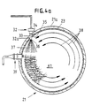
- FIG. 1 In connection with Fig. 1 reference herein shall generally be made to a two cycle combustion engine 10 having internal combustion. Especially there will be described such an engine 10 adapted according to a so-called "sine"-like concept.
- Fig. 1 there is specifically shown a combustion engine 10 according to the invention illustrated in cross-section and in a schematic manner.
- the aim according to a first aspect of the invention is combustion in a specially defined combustion chamber K1 (see Fig. 1b), as will be described in more detail below.
- the aim is a favourable control of opening and closing exhaust ports 25 and scavenging ports 24, as will be described further below.
- a drive shaft 11 in the form of a pipe stump, which passes axially and centrally through the engine 10.
- the drive shaft 11 is provided at its illustrated one end with a radially outwardly projecting, first head portion 12a, which forms a first cam guide device. at its other illustrated end the drive shaft 11 is provided with an equivalent radially outwardly projecting, second head portion 12b, which forms a second cam guide device.
- the head portions/ the cam guide devices 12a,12b in the illustrated embodiment are represented separately and are connected separately to the drive shaft 11 each with their fastening means.
- the cam guide device 12a surrounds the drive shaft 11 at its one end 11a and forms an end support against end surface 11b of the drive shaft 11 via a fastening flange 12a' and is stationarily secured to the drive shaft via fastening screws 12a''.
- the cam guide device 12b surrounds a thickened portion 11c of the drive shaft 11 at its opposite end portion lid.
- the cam guide device 12b is not, as is the cam guide device 12a directly secured to the drive shaft 11, but is on the other hand arranged axially displaceable a limited extent axially along the drive shaft 11, especially with the idea of being able to regulate the compression ratio in cylinders 21 of the engine 10 (only the one of a number of cylinders is shown in Fig. 1).
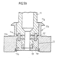
- End portion 11d (see Fig. 1 and 5a) of the drive shaft 11 forms a radially offset sleeve portion to which there is fastened cup-shaped carrying member 13.
- the carrying member 13 is provided with a fastening flange 13' which with fastening screws 13'' is secured to end portion 11d of the drive shaft 11.
- a pressure oil chamber 13b Between upper end surface 13a of the carrying member 13 and an opposite shoulder surface 11e of the drive shaft 11 there is defined a pressure oil chamber 13b.
- a compression simulator 12b' in the form of a piston-forming guide flange, which projects from the inner side of the cam guide device radially inwards into the pressure oil chamber 13b for sliding abutment against the outer surface of the end portion 11d.
- the guide flange 12b' is passed through by a series of guide pins 12' which are anchored in their respective bores in the end surface 13a of the carrying member 13 and in the shoulder surface 11e of the drive shaft 11.
- the pressure oil chamber 13b is supplied pressure oil and is drained of pressure oil via transverse ducts 11f and 11g through end portion lid of the drive shaft 11.
- An oil guide means 14 which is put axially inwards into mutually aligned axial bores in the end portion 11d of the drive shaft 11 and in fastening flange 13' of the carrying member 13, provides for pressure oil and return oil to be led to and from the ducts 11f and 11g via separate guide ducts 14a and 14b and adjacent annular grooves 14a' and 14b' in the oil guide means 14.
- Control of pressure oil and return oil to an from the pressure oil chamber 13b on opposite sides of the compression simulator 12b' of the cam guide device 12b takes place from a remotely disposed commercially conventional control arrangement, not shown further, in a manner not shown further.
- the drive shaft 11 is, as shown in Fig. 1, connected at opposite ends to equivalent drive shaft sleeves 15a and 15b.
- the sleeve 15a is fastened with fastening screws 15a' to the cam guide device 12a, while the sleeve 15b is fastened with fastening screws 15b' to the carrying member 13.
- the sleeves 15a and 15b are rotatably mounted in a respective one of two opposite main support bearings 16a,16b, which are fastened at opposite ends of the engine 10 in a respective end cover 17a and 17b.
- the end covers 17a and 17b are correspondingly fastened to an intermediate engine block 17 by means of fastening screws 17'.
- a first lubricating oil chamber 17c is defined between the end cover 17a and the engine block 17 and a second lubricating oil chamber 17d between the end cover 17b and the engine block 17.
- an extra cap 17e attached to the end cover 17b and an external oil conduit 17f between the lubricating oil chamber 17c and the oil cap 17e.
- a suction strainer 17g connected to a lubricating oil conduit 17h which forms a communication between the lubricating oil chamber 17d and an external lubricating oil arrangement (not shown further).
- the oil guide means 14 is provided with a cover-forming head portion 14c which is fastened to end cover 17b of the engine 10 with fastening screws 14c'.
- the cover-forming head portion 14c forms a sealing off relative to the lubricating oil chamber 17c endwise outside the support bearing 16b.
- the engine 10 is consequently generally constructed of a driven component, that is to say a rotatable component, and a driving component, that is to say a non-rotating component.
- the driven component comprises drive shaft 11 of the engine and carrying member 13 of the drive shaft and drive shaft sleeves 15a/15b plus the cam guide devices 12a and 12b, which are connected to the drive shaft 11.
- the driving, non-rotating component comprises cylinders 21 of the engine with associated pistons 44,45.
- the present invention there is ensured a regulation of the compression ratio of the engine by effecting a regulation internally, that is to say mutually between the parts of the driven component. More specifically the one cam guide device 12b is displaced axially backwards and forwards relative to the drive shaft 11, that is to say within the defined movement space in said pressure oil chamber 13a, which is determined by the guide flange 12b' and the part-chambers of the oil chamber 13a on opposite sides of the guide flange 12b'.
- a stepwise or stepless regulation of the compression ratios can be considered according to need, for example adapted with graduated control of the cam guide device 12b to respective positions relative to the drive shaft 11.
- the control can for example occur automatically by means of electronics known per se, based on different temperature sensing equipment, and the like.
- the control can occur by manual control via suitable regulation means, which are not shown further herein.
- Fig. 1 and 1b there is indicated by a broken line a centre space 44' between the piston heads of the pistons 44,45 at a normal compression ratio when the cam guide device 12b occupies the position illustrated in Fig. 1.
- a centre space 44'' between the piston heads of the pistons 44,45 when guide flange 12b' of the cam guide device 12b is pushed to the maximum upwardly against the shoulder surface 11e of the piston rod 11.
- the engine 10 is shown divided up into three stationary main components, that is to say a middle member, which constitutes the engine block 17 and two cover-forming housing members 17a,17b which are arranged at a respective one of the ends of the engine 10.
- the housing members 17b, 17c are consequently adapted to cover their respective cam guide devices 12a,12b, support wheels 53 and 55 and their associated bearings in respective piston rods 48,49 at their respective end of the engine block 17. All the driving and driven components of the engine are consequently effectively enclosed in the engine 10 and received in an oil bath in the associated lubricating oil chambers 17c and 17d.
- the three cylinders 21, which are placed around the drive shaft 11 with a mutual angular spacing of 120°, are designed according to the illustrated embodiment as separate cylinder-forming insert members, which are pushed into an associated bore in the engine block 17.
- each cylinder/ cylinder member 21 there is inserted a sleeve-shaped cylinder bushing 23.
- the bushing 23 there is designed, as shown further in Fig. 1a and 1b (see also Fig. 2 and 3), an annular series of scavenging ports 24 at one end of the bushing 23 and an annular series of exhaust ports 25 at the other end of the bushing 23.
- FIG. 1 there is shown an annular inlet duct 28 for scavenging air, which surrounds the scavenging ports 26, and a scavenging air intake 29 lying radially outside.
- the scavenging air ducts 28 extend at a significant oblique angle u relative to a radial plane A through the cylinder axis, specially adapted to put the scavenging air in a rotational path 38 internally in the cylinder 21, as is shown by an arrow B in Fig. 2.
- annular exhaust outlet duct 30 which surrounds the exhaust ports 27, plus an exhaust outlet 31 emptying radially outwards.
- Fig. 3 there is shown an equivalent oblique run of the exhaust ports 27 at an angle v relative to the radial plane A through the cylinder axis, specially adapted to lead the exhaust gases from the rotational path 38 internally in the cylinder in an equivalent rotational path outwards from the cylinder 21, as is shown by an arrow C.
- the exhaust ports 27 are shown opening radially outwards to facilitate the outward flow of the exhaust gas from the cylinder 21 outwards towards the exhaust outlet duct 30.
- the scavenging air is used to push out exhaust gas from a preceding combustion phase in the cylinder, in addition to supplying fresh air for a subsequent combustion process in the cylinder.
- a rotating air mass as shown by arrows 38 (see Fig. 1a and 4a) in working chamber K of the cylinder 21 in the compression stroke.
- a fuel injector or nozzle 32 received in a cavity 33 in the cylinder wall 21a.
- the injector/nozzle 32 has a pointed end 32' (see Fig. 4a) projecting through a bore 34 in the cylinder wall 21a.
- the bore 34 passes through the cylinder wall 21a at an oblique angle, which is not marked further in Fig. 4a, but which corresponds to the angle u, as shown in Fig. 2.
- the pointed end 32' projects further through a bore 35 in the bushing 23, in alignment with the bore 34.
- Mouth 36 (see Fig. 4a) of the nozzle/injector 32 is arranged so that a jet 37 of fuel can be directed, as is shown in Fig.
- Fig. 4b there is shown an alternative construction of the solution as shown in Fig. 4a, there being employed in addition to a first fuel nozzle 32 and a first ignition arrangement 39 a second fuel nozzle 32a and a second ignition arrangement 39a in one and the same disc-formed combustion chamber K1.
- Both the nozzles 32 and 32a are designed correspondingly as described with reference to Fig. 4a and both the ignition arrangements 39 and 39a are corresponding as described with reference to Fig. 4a.
- the associated components are designated with the reference designation "a" in addition.
- nozzles 32,32a are shown mutually displaced an angular arc of 180°, while the ignition arrangements 39,39a are correspondingly shown mutually displaced an angular arc of 180°.
- the relative spacings can be altered as required, that is to say with different mutual spacings, for instance depending upon the point in time of the mutual ignition, and the like.
- a cooling water system for general cooling of the cylinder 21.
- the cooling water system comprises a cooling water intake not shown further having a first annular cooling water duct 41 and a second annular cooling water duct 42.
- the ducts 41,42 are mutually connected via an annular series of axially extending connecting ducts 43 (see Fig. 3).
- the axially extending ducts 43 pass through the cylinder wall 21a in each intermediate zone 27a between the exhaust ports 27, so that these zones 27a especially can be prevented from superheating by being subjected locally to a flowing through of cooling medium.
- the discharge of cooling water which is not shown further in Fig. 1, is connected to the cooling water duct 42 remote from the cooling water intake, in a manner not shown further.
- pistons 44,45 Internally in the bushing 23 there are two axially movable pistons 44,45 movable towards and away from each other. Just by the respective top 44a,45a of the piston and by the skirt edge 44b,45b of the piston there is arranged a set of piston fourths 46 in a manner known per se .
- the pistons 44,45 are movable synchronously towards and away from each other in a two cycle engine system.
- the piston 44 is shown in the form of a relatively thin-walled cap having top portion 44a and skirt portion 44b. Innermost in the internal hollow space of the piston there is arranged a support disc 44c, thereafter follows a head member 48c for an associated piston rod 48, a support ring 44d and a clamping ring 44e.
- the head member 48c is provided with a convexly rounded top surface 48c' and concavely rounded off bottom surface 48c'', while the support disc 44c is designed with an equivalent concavely rounded upper support surface 44c' and the support ring 44d is provided with a convexly rounded lower support surface 44d'.
- the head member 48c is consequently adapted to be tilted about a theoretical axis relative to the piston controlled by the support surfaces 44c' and 44d'.
- the ring 44e provides for the head member 48c - and thereby the piston rod 48 - having a certain degree of fit and thereby a certain possibility of turning about said theoretical axis of the piston 44 during operation.
- the head member 48c is provided with a middle, sleeve-shaped carrying portion 48g having rib portions 48g' projecting laterally outwards which form a locking engagement with equivalent cavities (not shown further) internally in the associated piston rod 48 (see Fig. 1a and 1b).
- Fig. 1a the pistons 44,45 are shown in their equivalent, one outer position. This outer position, where there is a maximum spacing between the pistons 44,45, is designated herein generally as a dead point 0a for the piston 44 and 0b for the piston 45.
- dead portions there is defined in the working chamber K a so-called “dead space”, which herein (for reasons which will be evident from what follows) is designated as the combustion chamber K1.
- the combustion chamber K1 is according to the invention mainly defined in and at a transition portion between the compression phase and expansion phase of the two cycle engine, as will be described in more detail in what follows.
- the working chamber K is expanded from a minimum volume, shown by the combustion chamber K1, gradually to a maximum volume, as shown in Fig. 1a and at said dead point 0a and 0b in Fig. 9 and 10, the combustion chamber K1 being gradually expanded with another chamber K2 in which the expansion and compression strokes of the pistons 44,45 take place.
- the combustion chamber K1 is defined to a considerable degree in said dead portion/dead space. In practice however the combustion can also continue a bit just outside said dead space, something which will be explained in more detail below.
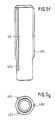
- Each piston 44,45 is rigidly connected to its respective pipe-shaped piston rod 48 and 49, which is guided in a rectilinear movement via a so-called cross-head control 50.
- the cross-head control 50 is arranged partly in the engine block 17 and partly in the respective cover member 17a and 17b at the equivalent free outer end of the respective piston rod 48,49.
- the cross-head control 50 which is shown in detail in Fig. 5a, forms an axial guide for the piston rod 48 and 49 just within and just outside the engine block 17.
- a rotary pin 51 which is fastened at one end of the pipe-shaped piston rod 48 and which passes through the piston rod 48 crosswise, that is to say through its pipe hollow space 52.
- a main castor 53 on a middle portion 51a of the rotary pin 51, that is to say internally in said hollow space 52, there is rotatably mounted a main castor 53, while on one end portion 51b of the rotary pin 51 on the outwardly facing side 48a of the piston rod 48 there is rotatably mounted an auxiliary castor 55.
- the main castor 53 comprises an inner hub portion 53a having a roller bearing 53b and an outer rim portion 53c.
- the rim portion 53c is provided with a double curved, that is to say ball sector-shaped roller surface 53c'.
- the auxiliary castor 55 has a construction corresponding to the main castor 53 and comprises an inner hub portion 55a, a middle roller bearing 55b and an outer rim portion 55c with ball sector-shaped roller surface 55c'.
- the main castor 53 is adapted to be rolled off along a roller surface 54 concavely curved in cross-section, which forms a part of a so-called "sine"-like curve 54' as shown in Fig. 6 - 8.
- a ball sector-shaped roller surface 53c' which rolls along an equivalently curved guide surface 54 of the cam guide device 12a and 12b, an effective support abutment can be ensured between the castor 53 and the guide surface 54 under varying working conditions, and possibly with a somewhat obliquely disposed castor and/or obliquely disposed piston rod 48 (49), such as this being able to be permitted in the pivotable mounting of the piston rod 48 in the piston 44, as shown in Fig. 5h.
- the "sine"-like curve 54' is designed in the cam guide device 12a and 12b of the drive shaft on a side facing equivalently axially outwards from the intermediate cylinder's 21.
- the auxiliary castor 55 is adapted to be rolled off against and along an equivalent, other "sine"-like curve (not shown further) concavely curved in cross-section along a roller surface 56a in a roller path, which is designed in the cam guide device 12a (and 12b) radially just within the roller surface 54.
- the "sine"-like curve 54a' is placed radially outermost, while the "sine"-like curve 56a' is placed in the cam guide device 12a a distance radially within the "sine"-like curve 54a'.
- the "sine"-like curve 54a' can be arranged radially within the "sine"-like curve 56a' (in a manner not shown further).
- each of the cam guide devices 12a and 12b there are designed a corresponding pair of "sine"-like curves 54a', 56a' in a manner not shown further and each "sine"-like curve can be provided with one or more "sine"-like planes as required.
- FIG. 1 schematic reference is made to a cam guide device 12a and 12b, while the details in the associated "sine"-like curves and "sine"-like planes are shown further in Fig. 9 - 14.
- each of the cam guide devices 12a and 12b a single "sine"-like plane (having a “sine"-like top and a “sine”-like bottom), that is to say the "sine"-like plane covers an angular arc of 360°, it is however immaterial whether an odd numbered or even numbered number of cylinders is employed.
- an odd numbered or even numbered number of cylinders there can for instance be employed a larger or smaller number of cylinders as required.
- the individual engine can be “internally” geared with respect to speed, all according to which number of “sine”-like tops and “sine”-like bottoms is to be employed at each 360° revolution of the drive shaft.
- both engines can be built precisely in the revolutions per minute region which is relevant for the individual application.
- the series arranged cylinders of the engine, with associated pistons, of the illustrated embodiment are arranged in specific angular positions around the axis of the drive shaft, for instance with mutually equal intermediate spaces along the "sine"-like plane or along the series of "sine"-like planes (the "sine"-like curve).
- the support rollers of the pistons are placed in the illustrated embodiment with equivalently equal angular intermediate spaces, that is to say in equivalent rotary angular positions along the "sine"-like curve, so that they are subjected one after the other to equivalent piston movements in equivalent positions along the respective "sine"- like planes.
- the engine power is consequently transferred from the different pistons 44,45 one after the other via the support rollers 53 in the axial direction for the drive shaft 11 via respective "sine"-like curves each with their “sine”-like plane, and the drive shaft 11 is thereby subjected to a compulsory rotation about its axis.
- the engine power is thereby transferred in an axial direction from support rollers of the piston rods to the "sine"-like planes, which are forcibly rotated together with the drive shaft 11 about its axis.
- the transfer of motive power is obtained from an oscillating piston movement to a rotational movement of the drive shaft, the motive power being transferred directly from respective support rollers of the piston rods to "sine"-like planes of the drive shaft.
- FIG. 6a there is schematically illustrated a support roller 53 on an obliquely extending portion of a "sine"-like curve 8a.
- Axial driving forces are shown from an associated piston 44 having piston rod 48 in the form of an arrow Fa and equivalently in a radial plane decomposed rotational forces transferred to the "sine"-like plane 8a shown by an arrow Fr.
- Fig. 6 - 8 there is schematically shown the mode of operation pf a three cylinder engine 10, in which only the one piston 44 is shown of the two co-operating pistons 44,45, illustrated in a planar spread condition along an associated "sine"-like curve 54', which consists of two mutually succeeding "sine"-like planes, plus the associated main castor 53 of the associated one piston rod 48.
- the associated one piston 44 in each of three cylinders 21 of the engine an equivalent arrangement being employed for the piston 45 at the opposite end of the cylinders.
- the cylinder 21 and the opposite piston 45 have been omitted from Fig.
- the "sine"-like curve 54' is shown with a lower roll path 54, which has a double “sine"-like plane-shaped contour and which generally guides the movement of the main castor 53 in an axial direction, in that it more or less constantly effects a downwardly directed force from the piston 44 via the main castor 53 towards the roll path 54 in the expansion stroke and an upwardly directed force from the roll path 54 via the main castor 53 towards the piston 44 in the compression stroke.
- the auxiliary castor 55 (not shown further in Fig. 6 - 8) is received with a sure fit relative to an upper roll path 54b, as is shown in Fig. 5a.
- the said roll path 56b is shown vertically above the main castor 53 in Fig.
- the auxiliary castor 55 is normally not active, but will control movement of the piston 44 in an axial direction in the instances the main castor 53 has a tendency to raise itself from the cam-forming roll path 54. During operation lifting of the main castor 53 in an unintentional manner relative to the roll path 54 can hereby be avoided.
- the roll path for the auxiliary castor 55 is, as shown in Fig. 5, normally arranged in the fixed fit spacing from the roll path of the main sector 53.
- Fig. 6 - 8 the "sine"-like curve 54' is shown with a first relatively steep and relatively rectilinear running curve portion 60 and a subsequent, more or less arcuate, top-forming transition portion/dead portion 61 and a second relatively more gently extending, relatively rectilinearly running curve portion 62 and a subsequent arcuate transition portion/dead portion 63.
- curve contours are however not representative in detail of the curve contours which are employed according to the invention, examples of the correct curve contours being shown in more detail in Fig. 12 and 13.
- the "sine"-like curve 54' and the "sine"-like plane 54 are shown in Fig. 6 - 8 with two tops 61 and two bottoms 63 and two pairs of curve portions 60,62.
- Fig. 6 - 8 there are illustrated three pistons 44 and their respective main castor 53 shown in equivalent positions along an associated "sine"-like curve in mutually different, succeeding positions.
- the relatively short first curve portions 60 entail that at all times only one main castor 53 will be found on the one short curve portion and two or roughly two main castors 53 on the two longer curve portions 62.
- different forms of curve portions can be employed for the compression stroke relative to the form of the curve portions for the expansion stroke.
- arc length for the expansion stroke of about 105° and an equivalent arc length for the compression stroke of about 75°.
- actual arc lengths can for instance lie between 110° and 95° when the expansion stroke is concerned and equivalently between 70° and 85° when the compression stroke is concerned.
- two tops 61 and two bottoms 63 are employed for each 360° revolution of the drive shaft 11, that is to say two expansion strokes per piston pair 44,45 per revolution.
- Fig. 14 there is schematically shown a midmost, theoretical cam guide curve 8c, which shows the volume change of the working chamber K from a minimum, as shown in the combustion chamber K1 in the dead zones 4a and 4b, to a maximum, as shown in the maximum working chamber K in the dead points 0a and 0b (see Fig. 9 - 10 and 12 - 14).
- the curve 8b as is illustrated in Fig. 12 - 14, is shown at the dead point 0b phase-displaced an angle of rotation of 14° in front of the dead point 0a of the curve 8a.
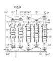
- Fig. 9 and 10 there are schematically illustrated five cylinders 21-1, 21-2, 21-3, 21-4 and 21-5 and belonging to two associated curves 8a and two curves 8b, shown spread in a schematically illustrating manner in one and the same plane.
- the five cylinders 21-1, 21-2, 21-3, 21-4 and 21-5 are shown in respective angular positions with a mutual angular space of 72°, that is to say in positions which are uniformly distributed around the axis of the rotary shaft 11.
- a first curve 8a which covers an arc length of 180° from a position 0°/360° to a position 180°.
- a corresponding curve 8a passes over a corresponding arc length of 180° from position 180° to position 360°. In other words two succeeding curves 8a for each 360° revolution of the drive shaft.
- the curve 8a shows in position 0°/360° a first dead point 0a. From position 0° to a position 38.4° there is shown a first transition portion 1a, which corresponds to a first part of a compression stroke and from position 38.4° to position 59.2° an obliquely (upwardly) extending rectilinear portion 2a, which corresponds to a main part of the compression stroke and from position 59.2° to a position 75° a second transition portion 3a, which corresponds to a finishing part of the compression stroke.
- transition portion 5a From the position 80° to a position 95.8° there is shown a transition portion 5a, from the position 95.8° to a position 160° an oblique downwardly extending, rectilinear portion 6a and from the position 160° to a position 180° a transition portion 7a.
- the three portions 5a,6a,7a together constitute an expansion portion.
- Fig. 13 there is shown an equivalent (mirror image) curve contour for the remaining curve 8b, shown with a dead point 0b and succeeding curve portion 1b-7b.
- the cam guide continues with a corresponding curve 8b between the positions 166° and 346° (see Fig. 10).
- the first curve 8a (Fig. 12) controls opening (position 160°/340°) and closing (position 205°/25°) of exhaust ports 25.
- the second curve 8b (Fig. 13) control opening (position 146°/326°) and closing (position 185°/5°) of scavenging ports 24.
- Fig. 14 there is shown a phase-displacement of 14° between the dead points 0a and 0b, in the illustrated, schematic comparison of the curves 8a and 8b.
- Curve 8b as shown by broken lines in Fig. 14, is for comparative reasons shown in mirror image form relative to the curve 8a, which for its part is shown in full lines in Fig. 14.
- curve 8c By chain lines there is shown the midmost, theoretical curve 8c, which illustrates a curve contour approximately like or more like a mathematical "sine"-like curve-contour.
- Fig. 9 and 10 there is shown the "sine"-like plane 8b in a position 14° in front of the position for the "sine"-like plane 8a.
- the five said cylinders 21-1, 21-2, 21-3, 21-4 and 21-5 are shown in successive positions relative to the associated "sine"-like plane and individually in successive working positions, as shown in the following diagram 1 and diagram 2.
- Diagram 1 with reference to Fig. 9 and Fig. 12 - 13. Cylinder No.
- the exhaust ports 25 are held on the other hand open over an arc length of 39°, that is to say over an arc length which is phase-displaced 14° relative to the arc length in which the scavenging ports are open (see Fig. 14).
- the scavenging ports 24 can consequently be open over an arc length of 20° (see the curve portions 1a - 3a in Fig. 12 and the single hatched section A' in Fig. 14) after the exhaust ports 25 are closed.
- This means that the compression chamber over the last-mentioned arc length of 20° can inter alia be supplied an excess of scavenging air, that is to say is overloaded with compressed air.
- Diagram 2 with reference to Fig. 10 and Fig. 12 - 13. Cylinder No.
- the said sections A' and B' show the axial dimensions of the exhaust ports 25 and the axial dimensions of the scavenging ports 24 in a respective outer portion of the working chamber K.
- the ports 24 and 25 can thereby be designed of equal height in each end of the working chamber K. The said height is shown in Fig. 12 -14 by 12.
- Fig. 14 the contours of the respective two curves 8a,8b, which are shown schematically in mirror image relative to each other will be evident.
- Curve 8a is shown real with a full line
- curve 8b is shown with a broken line, in mirror image about a middle axis between the pistons 44,45.
- the curve 8c shows a theoretical midmost curve between the curves 8a,8b. It will be evident that the midmost curve 8c has a contour which lies more closely up to a sine curve contour than the contours of the curves 8a,8b individually. Consequently, even if one gets a relatively unsymmetrical contour in the curves 8a,8b mutually, a relatively symmetrical contour of the midmost curve 8c can be achieved.
- the fuel is injected in a jet with a flow into the rotating scavenging air current and is mixed/atomised effectively in the rotating scavenging air current.
- the combustion starts immediately after ignition and is accomplished mainly over a limited region in which the pistons roughly occupy a maximum pushed in position, that is to say at the close of the curve zone 3a,3b, that is to say in a region where the pistons are subjected to minimal axial movement.
- the combustion proceeds mainly or to a significant extent where the pistons 44,45 are held at rest in the inner dead portion 4a and 4b, that is to say over an are length of 10° and 5° respectively.
- the combustion continues as required to a greater or smaller degree in the following transition portion 5a,5b and in the main expansion portion 6a,6b, depending upon the speed of rotation of the rotary shaft.
- the combustion chamber can be allowed to be expanded to the portion 5a,5b just outside the dead portion 4a,4b with largely corresponding advantages in a defined volume of the working chamber K.
- the speed of combustion is as known of an order of magnitude of 20 - 25 meters per second.
- the combustion area can be effectively covered over the whole of the disc-shaped combustion chamber K1. In practice especially favourable combustion can thereby be achieved with relatively short flame lengths.
- a ceramic ring that is to say a ceramic coating applied in an annular zone of the working chamber K corresponding to a combustion region (3a - 5a, 3b, 5b), so that high temperatures can be employed especially in the combustion chamber K1, but also in the following portion 5a,5b of the combustion region.
- the ceramic ring which is shown with a dimension as indicated by a broken line 70 in Fig. 12 - 14, comprises the whole combustion chamber K1 and is in addition extended further outwards in the combustion chamber over a distance 13.
- the compression phase takes place relative to the curves 8a,8b under angles of inclination of between about 25° and about 36° in the respective two curves 8a and 8b, that is to say with a mean angle (see Fig. 14) of about 30°. If desired the angles of inclination (and the mean angle) can for instance be increased to about 45° or more as required.
- the expansion phase takes place correspondingly in the illustrated embodiment at between about 22° and 27° in the two curves 8a and 8b, that is to say while at a mean angle (see Fig. 14) of about 24°.
- a still additional increase of the rotational effect can be obtained according to the construction as shown in Fig. 4b by the application of an extra (second) fuel nozzle 37a, which is disposed angularly displaced relative to the first fuel nozzle 37, and by the application of an extra ignition arrangement 39a, which is disposed angularly displaced relative to the first ignition arrangement 39.
- the exhaust ports 25 open again, on the termination of the working cycle, the exhaust gas is exhausted with a high speed of movement, that is to say with a high rotational speed, during exhaustion of exhaust gas via the said obliquely disposed exhaust ports.
- a constructional solution for such a regulation according to the invention is based on pressure oil - controlled regulating technique.
- pressure oil - controlled regulating technique there can be employed for instance electron-controlled regulating technique, which is not shown further herein, for regulating the compression ratio.
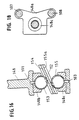
- Fig. 15 and 16 there is shown schematically an alternative solution of certain details in a cam guide device, as it is referred to herein by the reference numeral 112a, and of an associated piston rod, as shown by the reference numeral 148 as well as a pair of pressure rollers, as shown by the reference numerals 153 and 155.
- the cam guide device 112a is a cam guide device
- the cam guide device 12a is shown having a relatively space-demanding design with associated casters 53 and 55 arranged at the side of each other in the radial direction of the cam guide device 12a, that is to say with the one caster 53 arranged radially outside the remaining caster 55 and with the associated "sine"-like grooves 54,55c illustrated correspondingly radially separated on each of their radial projections.
- the cam guide device 112a is shown with associated pressure spheres 153, 155 arranged in succession in the axial direction of the cam guide device 112a, that is to say with a sphere on each respective side of an individual, common projection, illustrated in the form of an intermediate annular flange 112.
- the annular flange 112 is shown with an upper "sine"-like curve forming "sine"-like groove 154 for guiding an upper pressure sphere 153, which forms the main support sphere of the piston rod 148, and a lower “sine"-like curve forming "sine"-like groove 155a for guiding a lower pressure sphere 155, which forms the auxiliary support sphere of the piston rod 148.
- the grooves 154 and 155a have, as shown in Fig. 15, a laterally concavely rounded form corresponding to the spherical contour of the spheres 153,155.
- the annular flange 112 is shown having a relatively low thickness, but the low thickness can be compensated for as to strength in that the annular flange 112 has in the peripheral direction a self-reinforcing "sine"-like curve contour, such as indicated by the obliquely extending section of the annular flange illustrated in Fig. 16.
- the annular flange 112 is shown segmentally in section, while in Fig. 16 there is shown in cross-section a peripherally locally defined segment of the annular flange 112, seen from the inner side of the annular flange 112.
- the piston rod 148 The piston rod 148:
- a pipe-shaped, relatively voluminous piston rod 48 is shown, while in the alternative embodiment according to Fig. 15 and 16 there is illustrated a slimmer, compact, rod-shaped piston rod 148 having a C-shaped head portion 148a with two mutually opposite sphere holders 148b,148c for a respective pressure sphere 153,155.
- the piston rod 148 can in a manner not shown further be provided with external screw threads which cooperate with internal screw threads in the head portion, so that the piston rod and thereby the associated sphere holder 148b can be adjusted into desired axial positions relative to the head portion 148a. This can inter alia facilitate the mounting of the sphere holder 148b and its associated sphere 153 relative to the annular flange 112.
- annular flange 112 is shown with a minimum thickness at obliquely extending portions of the annular flange, while the annular flange 112 can have in a manner not shown further a greater thickness at the peaks and valleys of the "sine"-like curve, so that a uniform or largely uniform distance can be ensured between the spheres 153,154 along the whole periphery of the annular flange.
- a lubricating oil intake which internally in the C-shaped head portion 148a branches off into a first duct 101 to a lubricating oil outlet 102 in the upper sphere holder 148b and into a second duct 103 to a lubricating oil outlet 104 in the lower sphere holder 148c.
- pressure spheres 153,155 are shown according to Fig. 15 and 16.
- the pressure spheres 153,155 are mainly adapted to be rolled relatively rectilinearly along the associated "sine"-like grooves 154,155a, but can in addition be permitted to be rolled sideways to a certain degree in the respective groove as required.
- the spheres 153 and 155 are designed identically, so that the sphere holders 145a,148b and their associated sphere beds can also be designed mutually identically and so that the "sine"-like curves 154/155a can also be designed mutually identically.
- the pressure spheres 153,155 are shown hollow and shell-shaped with a relatively low wall thickness. There are obtained hereby pressure spheres of low weight and small volume, and in addition there is achieved a certain elasticity in the sphere for locally relieving extreme pressure forces which arise in the sphere per se.
- a pair of guide rods 105,106 are shown which pass through internal guide grooves 107,108 along opposite sides of the head portion 148a of the piston rod 148.
Landscapes
- Engineering & Computer Science (AREA)
- Mechanical Engineering (AREA)
- General Engineering & Computer Science (AREA)
- Chemical & Material Sciences (AREA)
- Combustion & Propulsion (AREA)
- Output Control And Ontrol Of Special Type Engine (AREA)
- Valve-Gear Or Valve Arrangements (AREA)
- Valve Device For Special Equipments (AREA)
- Combustion Methods Of Internal-Combustion Engines (AREA)
- Cylinder Crankcases Of Internal Combustion Engines (AREA)
- Carbon And Carbon Compounds (AREA)
- Hydraulic Motors (AREA)
- Reciprocating Pumps (AREA)
- Electrical Control Of Air Or Fuel Supplied To Internal-Combustion Engine (AREA)
- Transmission Devices (AREA)
- Pistons, Piston Rings, And Cylinders (AREA)
Applications Claiming Priority (3)
| Application Number | Priority Date | Filing Date | Title |
|---|---|---|---|
| NO971907 | 1997-04-25 | ||
| NO971907A NO305619B1 (no) | 1997-04-25 | 1997-04-25 | Anordning ved forbrenningsmotor med innvendig forbrenning |
| PCT/NO1998/000125 WO1998049437A1 (en) | 1997-04-25 | 1998-04-22 | Arrangement in a two cycle combustion engine with internal combustion |
Publications (2)
| Publication Number | Publication Date |
|---|---|
| EP0977939A1 EP0977939A1 (en) | 2000-02-09 |
| EP0977939B1 true EP0977939B1 (en) | 2002-06-19 |
Family
ID=19900656
Family Applications (1)
| Application Number | Title | Priority Date | Filing Date |
|---|---|---|---|
| EP98920741A Expired - Lifetime EP0977939B1 (en) | 1997-04-25 | 1998-04-22 | Arrangement in a two cycle combustion engine with internal combustion |
Country Status (20)
| Country | Link |
|---|---|
| US (2) | US6202605B1 (pl) |
| EP (1) | EP0977939B1 (pl) |
| JP (1) | JP2001523315A (pl) |
| KR (1) | KR20010020295A (pl) |
| CN (1) | CN1089849C (pl) |
| AT (1) | ATE219552T1 (pl) |
| AU (1) | AU726454B2 (pl) |
| BR (1) | BR9808973A (pl) |
| CA (1) | CA2285107C (pl) |
| CZ (1) | CZ291215B6 (pl) |
| DE (1) | DE69806148T2 (pl) |
| DK (1) | DK0977939T3 (pl) |
| ES (1) | ES2178834T3 (pl) |
| HU (1) | HUP0000722A3 (pl) |
| NO (1) | NO305619B1 (pl) |
| NZ (1) | NZ337970A (pl) |
| PL (1) | PL190067B1 (pl) |
| PT (1) | PT977939E (pl) |
| RU (1) | RU2178527C2 (pl) |
| WO (1) | WO1998049437A1 (pl) |
Families Citing this family (18)
| Publication number | Priority date | Publication date | Assignee | Title |
|---|---|---|---|---|
| AUPQ676700A0 (en) | 2000-04-07 | 2000-05-11 | Stokes, Warwick James | Improvements to internal combustion engines |
| GB2367328A (en) * | 2000-09-15 | 2002-04-03 | William Fairney | I.c. engine with opposed pistons and cam surfaces to transmit the piston movements |
| NO315532B1 (no) * | 2001-12-14 | 2003-09-15 | Smc Sinus Motor Concept As | Anordning ved en totakts forbrenningsmotor |
| CN101240745B (zh) * | 2001-12-18 | 2013-04-24 | 机械革新有限公司 | 用于内燃机的燃烧气缸 |
| RU2230919C1 (ru) * | 2002-10-22 | 2004-06-20 | Пошехонов Анатолий Викторович | Четырехтактный двигатель внутреннего сгорания |
| RU2296871C1 (ru) * | 2005-08-08 | 2007-04-10 | Павел Иванович Чернявских | Многоцилиндровый бесшатунный оппозитный четырехтактный двигатель внутреннего сгорания |
| CN101078353B (zh) * | 2007-05-23 | 2010-11-03 | 李贤举 | 动力机械装置 |
| RU2347095C1 (ru) * | 2007-06-05 | 2009-02-20 | Эдуард Дмитриевич Житников | Крейцкопфный поршень с опорным колпаком |
| PL216801B1 (pl) | 2009-09-18 | 2014-05-30 | Dariusz Wójtowicz | Silnik wielocylindrowy zwłaszcza na sprężone gazy lub spalinowy wewnętrznego spalania ze zmiennym stopniem sprężania |
| GB2477272B (en) | 2010-01-27 | 2014-06-25 | Two Stroke Developments Ltd | Internal combustion engine comprising piston dwell mechanism |
| GB2482565B (en) * | 2010-08-07 | 2012-06-20 | Fairdiesel Ltd | Internal combustion engine |
| WO2012019656A1 (de) * | 2010-08-13 | 2012-02-16 | Formtech Technologies Gmbh | Schrägscheibenmotor |
| JP6039503B2 (ja) * | 2013-05-21 | 2016-12-07 | 株式会社デンソー | 内燃機関 |
| DE102013105217A1 (de) * | 2013-05-22 | 2014-11-27 | Illinois Tool Works Inc. | Kompressor zum Erzeugen eines Druckmediums |
| GB2517763B (en) * | 2013-08-30 | 2017-12-27 | Newlenoir Ltd | Piston arrangement and internal combustion engine |
| CN105201645B (zh) * | 2014-05-05 | 2018-12-18 | 龙全洪 | 联通内燃机 |
| JP2019214943A (ja) * | 2018-06-11 | 2019-12-19 | トヨタ自動車株式会社 | 内燃機関 |
| US10598089B1 (en) | 2018-11-07 | 2020-03-24 | Hts Llc | Opposed piston engine with parallel combustion chambers |
Family Cites Families (12)
| Publication number | Priority date | Publication date | Assignee | Title |
|---|---|---|---|---|
| US1352985A (en) * | 1918-04-20 | 1920-09-14 | Murphy Engineering Company | Explosive-engine |
| US1802902A (en) * | 1928-05-12 | 1931-04-28 | Brau Marcel | Internal-combustion engine |
| DE2849783A1 (de) * | 1978-04-25 | 1979-11-08 | Charles Gwin Renegar | Verbrennungskraftmaschine mit gegenueberliegenden, gefuehrten kolben und nockenantrieben |
| US4432310A (en) * | 1979-05-03 | 1984-02-21 | Leonard J. E. Waller | Parallel cylinder internal combustion engine |
| GB2134982B (en) * | 1983-02-15 | 1986-07-02 | Commw Of Australia | Internal combustion engine |
| US4635590A (en) * | 1983-04-28 | 1987-01-13 | Anthony Gerace | Internal combustion engine and operating cycle therefor |
| GB8404159D0 (en) * | 1984-02-17 | 1984-03-21 | Sophocles Papanicolacu J P | Ic engine |
| CA1325897C (en) * | 1988-08-29 | 1994-01-11 | Brian Leslie Powell | Crankless reciprocating machine |
| US5215045A (en) * | 1992-07-08 | 1993-06-01 | Ivan Vadnjal | Cam drive internal combustion engine |
| US5507253A (en) * | 1993-08-27 | 1996-04-16 | Lowi, Jr.; Alvin | Adiabatic, two-stroke cycle engine having piston-phasing and compression ratio control system |
| DE4335515C2 (de) * | 1993-10-19 | 1996-07-04 | Otto C Pulch | Gegenkolben-Zweitakt-Verbrennungsmotor mit Fremdzündung, Kraftstoff-Direkteinspritzung in den Zylinder und Schichtladung |
| JPH07293325A (ja) * | 1994-04-20 | 1995-11-07 | Aisin Seiki Co Ltd | 内燃機関のピストン |
-
1997
- 1997-04-25 NO NO971907A patent/NO305619B1/no unknown
-
1998
- 1998-04-22 EP EP98920741A patent/EP0977939B1/en not_active Expired - Lifetime
- 1998-04-22 DE DE69806148T patent/DE69806148T2/de not_active Expired - Fee Related
- 1998-04-22 AT AT98920741T patent/ATE219552T1/de not_active IP Right Cessation
- 1998-04-22 WO PCT/NO1998/000125 patent/WO1998049437A1/en not_active Ceased
- 1998-04-22 PL PL98336388A patent/PL190067B1/pl not_active IP Right Cessation
- 1998-04-22 BR BR9808973-0A patent/BR9808973A/pt not_active IP Right Cessation
- 1998-04-22 ES ES98920741T patent/ES2178834T3/es not_active Expired - Lifetime
- 1998-04-22 AU AU73517/98A patent/AU726454B2/en not_active Ceased
- 1998-04-22 CA CA002285107A patent/CA2285107C/en not_active Expired - Fee Related
- 1998-04-22 PT PT98920741T patent/PT977939E/pt unknown
- 1998-04-22 DK DK98920741T patent/DK0977939T3/da active
- 1998-04-22 KR KR1019997009899A patent/KR20010020295A/ko not_active Abandoned
- 1998-04-22 CN CN98804487A patent/CN1089849C/zh not_active Expired - Fee Related
- 1998-04-22 CZ CZ19993776A patent/CZ291215B6/cs not_active IP Right Cessation
- 1998-04-22 HU HU0000722A patent/HUP0000722A3/hu unknown
- 1998-04-22 JP JP54685498A patent/JP2001523315A/ja not_active Ceased
- 1998-04-22 NZ NZ337970A patent/NZ337970A/en unknown
- 1998-04-22 RU RU99125111/06A patent/RU2178527C2/ru not_active IP Right Cessation
- 1998-04-22 US US09/319,035 patent/US6202605B1/en not_active Expired - Fee Related
-
1999
- 1999-10-20 US US09/420,630 patent/US6289791B1/en not_active Expired - Fee Related
Also Published As
| Publication number | Publication date |
|---|---|
| ES2178834T3 (es) | 2003-01-01 |
| KR20010020295A (ko) | 2001-03-15 |
| NZ337970A (en) | 2001-06-29 |
| ATE219552T1 (de) | 2002-07-15 |
| NO305619B1 (no) | 1999-06-28 |
| EP0977939A1 (en) | 2000-02-09 |
| US6202605B1 (en) | 2001-03-20 |
| PT977939E (pt) | 2002-11-29 |
| HUP0000722A3 (en) | 2001-05-28 |
| CN1253608A (zh) | 2000-05-17 |
| WO1998049437A1 (en) | 1998-11-05 |
| CZ377699A3 (cs) | 2000-03-15 |
| CN1089849C (zh) | 2002-08-28 |
| AU7351798A (en) | 1998-11-24 |
| AU726454B2 (en) | 2000-11-09 |
| CA2285107C (en) | 2006-12-19 |
| PL190067B1 (pl) | 2005-10-31 |
| NO971907L (no) | 1998-10-26 |
| NO971907D0 (no) | 1997-04-25 |
| DE69806148T2 (de) | 2003-02-13 |
| JP2001523315A (ja) | 2001-11-20 |
| DK0977939T3 (da) | 2002-10-14 |
| RU2178527C2 (ru) | 2002-01-20 |
| CZ291215B6 (cs) | 2003-01-15 |
| PL336388A1 (en) | 2000-06-19 |
| US6289791B1 (en) | 2001-09-18 |
| CA2285107A1 (en) | 1998-11-05 |
| DE69806148D1 (de) | 2002-07-25 |
| BR9808973A (pt) | 2000-08-01 |
| HUP0000722A2 (hu) | 2000-06-28 |
Similar Documents
| Publication | Publication Date | Title |
|---|---|---|
| EP0977939B1 (en) | Arrangement in a two cycle combustion engine with internal combustion | |
| EP0977938B1 (en) | Arrangement in a combustion engine with internal combustion | |
| US4635590A (en) | Internal combustion engine and operating cycle therefor | |
| HUE026639T2 (en) | Internal combustion engine | |
| US4030471A (en) | Opposed piston engine | |
| US2080846A (en) | Internal combustion engine | |
| EP0489208B1 (en) | Rotary engine, pump or compressor, with triangular cylinder | |
| US6250264B1 (en) | Internal combustion engine with arrangement for adjusting the compression ratio | |
| JP2005501993A (ja) | 改良型往復内燃機関 | |
| US2706970A (en) | High compression ignition internal combustion engines | |
| WO1991002889A1 (en) | Piston machine | |
| US7100549B2 (en) | Mechanism including a piston-and-cylinder assembly | |
| RU2097588C1 (ru) | Роторно-поршневой многокулачковый четырехтактный двигатель-3 | |
| MXPA99009786A (en) | Arrangement in a two cycle combustion engine with internal combustion | |
| CA1196578A (en) | Internal combustion engine | |
| SU1740699A1 (ru) | Аксиально-поршневой двигатель | |
| RU2002121075A (ru) | Механизм для преобразования поступательного перемещения во вращательное движение и наоборот | |
| RU2161710C2 (ru) | Двигатель внутреннего сгорания с регулируемой степенью сжатия | |
| JP2000291442A (ja) | 2列のシリンダを備えるクロスヘッドエンジン | |
| SK75893A3 (en) | Piston motor | |
| JPH074201A (ja) | 機関本体が回転する燃料噴射内燃機関 |
Legal Events
| Date | Code | Title | Description |
|---|---|---|---|
| PUAI | Public reference made under article 153(3) epc to a published international application that has entered the european phase |
Free format text: ORIGINAL CODE: 0009012 |
|
| 17P | Request for examination filed |
Effective date: 19990602 |
|
| AK | Designated contracting states |
Kind code of ref document: A1 Designated state(s): AT BE CH CY DE DK ES FI FR GB GR IE IT LI LU MC NL PT SE |
|
| GRAG | Despatch of communication of intention to grant |
Free format text: ORIGINAL CODE: EPIDOS AGRA |
|
| 17Q | First examination report despatched |
Effective date: 20010723 |
|
| GRAG | Despatch of communication of intention to grant |
Free format text: ORIGINAL CODE: EPIDOS AGRA |
|
| GRAH | Despatch of communication of intention to grant a patent |
Free format text: ORIGINAL CODE: EPIDOS IGRA |
|
| GRAH | Despatch of communication of intention to grant a patent |
Free format text: ORIGINAL CODE: EPIDOS IGRA |
|
| GRAA | (expected) grant |
Free format text: ORIGINAL CODE: 0009210 |
|
| AK | Designated contracting states |
Kind code of ref document: B1 Designated state(s): AT BE CH CY DE DK ES FI FR GB GR IE IT LI LU MC NL PT SE |
|
| REF | Corresponds to: |
Ref document number: 219552 Country of ref document: AT Date of ref document: 20020715 Kind code of ref document: T |
|
| REG | Reference to a national code |
Ref country code: GB Ref legal event code: FG4D |
|
| REG | Reference to a national code |
Ref country code: CH Ref legal event code: EP |
|
| REG | Reference to a national code |
Ref country code: IE Ref legal event code: FG4D |
|
| REF | Corresponds to: |
Ref document number: 69806148 Country of ref document: DE Date of ref document: 20020725 |
|
| REG | Reference to a national code |
Ref country code: DK Ref legal event code: T3 |
|
| REG | Reference to a national code |
Ref country code: GR Ref legal event code: EP Ref document number: 20020403134 Country of ref document: GR |
|
| REG | Reference to a national code |
Ref country code: PT Ref legal event code: SC4A Free format text: AVAILABILITY OF NATIONAL TRANSLATION Effective date: 20020919 |
|
| ET | Fr: translation filed | ||
| REG | Reference to a national code |
Ref country code: ES Ref legal event code: FG2A Ref document number: 2178834 Country of ref document: ES Kind code of ref document: T3 |
|
| REG | Reference to a national code |
Ref country code: CH Ref legal event code: NV Representative=s name: ISLER & PEDRAZZINI AG |
|
| PG25 | Lapsed in a contracting state [announced via postgrant information from national office to epo] |
Ref country code: LU Free format text: LAPSE BECAUSE OF NON-PAYMENT OF DUE FEES Effective date: 20030422 Ref country code: CY Free format text: LAPSE BECAUSE OF FAILURE TO SUBMIT A TRANSLATION OF THE DESCRIPTION OR TO PAY THE FEE WITHIN THE PRESCRIBED TIME-LIMIT Effective date: 20030422 |
|
| PLBE | No opposition filed within time limit |
Free format text: ORIGINAL CODE: 0009261 |
|
| STAA | Information on the status of an ep patent application or granted ep patent |
Free format text: STATUS: NO OPPOSITION FILED WITHIN TIME LIMIT |
|
| PG25 | Lapsed in a contracting state [announced via postgrant information from national office to epo] |
Ref country code: MC Free format text: LAPSE BECAUSE OF NON-PAYMENT OF DUE FEES Effective date: 20030430 |
|
| 26N | No opposition filed |
Effective date: 20030320 |
|
| GBPC | Gb: european patent ceased through non-payment of renewal fee |
Effective date: 20040422 |
|
| REG | Reference to a national code |
Ref country code: GB Ref legal event code: 728V |
|
| REG | Reference to a national code |
Ref country code: GB Ref legal event code: 728Y |
|
| PGFP | Annual fee paid to national office [announced via postgrant information from national office to epo] |
Ref country code: IT Payment date: 20060430 Year of fee payment: 9 |
|
| PGFP | Annual fee paid to national office [announced via postgrant information from national office to epo] |
Ref country code: GB Payment date: 20061018 Year of fee payment: 9 |
|
| PGFP | Annual fee paid to national office [announced via postgrant information from national office to epo] |
Ref country code: IE Payment date: 20061020 Year of fee payment: 9 |
|
| PGFP | Annual fee paid to national office [announced via postgrant information from national office to epo] |
Ref country code: FI Payment date: 20061026 Year of fee payment: 9 Ref country code: SE Payment date: 20061026 Year of fee payment: 9 Ref country code: DE Payment date: 20061026 Year of fee payment: 9 |
|
| PGFP | Annual fee paid to national office [announced via postgrant information from national office to epo] |
Ref country code: FR Payment date: 20061027 Year of fee payment: 9 Ref country code: PT Payment date: 20061027 Year of fee payment: 9 Ref country code: GR Payment date: 20061027 Year of fee payment: 9 Ref country code: CH Payment date: 20061027 Year of fee payment: 9 Ref country code: AT Payment date: 20061027 Year of fee payment: 9 |
|
| PGFP | Annual fee paid to national office [announced via postgrant information from national office to epo] |
Ref country code: DK Payment date: 20061031 Year of fee payment: 9 Ref country code: NL Payment date: 20061031 Year of fee payment: 9 |
|
| PGFP | Annual fee paid to national office [announced via postgrant information from national office to epo] |
Ref country code: BE Payment date: 20061114 Year of fee payment: 9 |
|
| PGFP | Annual fee paid to national office [announced via postgrant information from national office to epo] |
Ref country code: ES Payment date: 20061127 Year of fee payment: 9 |
|
| REG | Reference to a national code |
Ref country code: HK Ref legal event code: WD Ref document number: 1025613 Country of ref document: HK |
|
| REG | Reference to a national code |
Ref country code: PT Ref legal event code: NF4A Free format text: RESTITUTIO IN INTEGRUM Effective date: 20061027 |
|
| REG | Reference to a national code |
Ref country code: CH Ref legal event code: PCAR Free format text: ISLER & PEDRAZZINI AG;POSTFACH 1772;8027 ZUERICH (CH) |
|
| REG | Reference to a national code |
Ref country code: PT Ref legal event code: MM4A Free format text: LAPSE DUE TO NON-PAYMENT OF FEES Effective date: 20071022 |
|
| REG | Reference to a national code |
Ref country code: DK Ref legal event code: EBP |
|
| REG | Reference to a national code |
Ref country code: CH Ref legal event code: PL |
|
| GBPC | Gb: european patent ceased through non-payment of renewal fee |
Effective date: 20070422 |
|
| BERE | Be: lapsed |
Owner name: *SINUS HOLDING A/S Effective date: 20070430 |
|
| NLV4 | Nl: lapsed or anulled due to non-payment of the annual fee |
Effective date: 20071101 |
|
| PG25 | Lapsed in a contracting state [announced via postgrant information from national office to epo] |
Ref country code: PT Free format text: LAPSE BECAUSE OF NON-PAYMENT OF DUE FEES Effective date: 20071022 Ref country code: NL Free format text: LAPSE BECAUSE OF NON-PAYMENT OF DUE FEES Effective date: 20071101 Ref country code: FI Free format text: LAPSE BECAUSE OF NON-PAYMENT OF DUE FEES Effective date: 20070422 Ref country code: DE Free format text: LAPSE BECAUSE OF NON-PAYMENT OF DUE FEES Effective date: 20071101 |
|
| REG | Reference to a national code |
Ref country code: IE Ref legal event code: MM4A |
|
| PG25 | Lapsed in a contracting state [announced via postgrant information from national office to epo] |
Ref country code: AT Free format text: LAPSE BECAUSE OF NON-PAYMENT OF DUE FEES Effective date: 20070422 Ref country code: CH Free format text: LAPSE BECAUSE OF NON-PAYMENT OF DUE FEES Effective date: 20070430 Ref country code: LI Free format text: LAPSE BECAUSE OF NON-PAYMENT OF DUE FEES Effective date: 20070430 |
|
| PG25 | Lapsed in a contracting state [announced via postgrant information from national office to epo] |
Ref country code: BE Free format text: LAPSE BECAUSE OF NON-PAYMENT OF DUE FEES Effective date: 20070430 |
|
| PG25 | Lapsed in a contracting state [announced via postgrant information from national office to epo] |
Ref country code: GB Free format text: LAPSE BECAUSE OF NON-PAYMENT OF DUE FEES Effective date: 20070422 Ref country code: DK Free format text: LAPSE BECAUSE OF NON-PAYMENT OF DUE FEES Effective date: 20070430 |
|
| PG25 | Lapsed in a contracting state [announced via postgrant information from national office to epo] |
Ref country code: IE Free format text: LAPSE BECAUSE OF NON-PAYMENT OF DUE FEES Effective date: 20070423 |
|
| PG25 | Lapsed in a contracting state [announced via postgrant information from national office to epo] |
Ref country code: SE Free format text: LAPSE BECAUSE OF NON-PAYMENT OF DUE FEES Effective date: 20070423 |
|
| REG | Reference to a national code |
Ref country code: ES Ref legal event code: FD2A Effective date: 20070423 |
|
| PG25 | Lapsed in a contracting state [announced via postgrant information from national office to epo] |
Ref country code: FR Free format text: LAPSE BECAUSE OF NON-PAYMENT OF DUE FEES Effective date: 20070430 |
|
| PG25 | Lapsed in a contracting state [announced via postgrant information from national office to epo] |
Ref country code: GR Free format text: LAPSE BECAUSE OF NON-PAYMENT OF DUE FEES Effective date: 20071102 Ref country code: ES Free format text: LAPSE BECAUSE OF NON-PAYMENT OF DUE FEES Effective date: 20070423 |
|
| PG25 | Lapsed in a contracting state [announced via postgrant information from national office to epo] |
Ref country code: IT Free format text: LAPSE BECAUSE OF NON-PAYMENT OF DUE FEES Effective date: 20070422 |