EP0977936B1 - Ansaugeinrichtung - Google Patents
Ansaugeinrichtung Download PDFInfo
- Publication number
- EP0977936B1 EP0977936B1 EP98925405A EP98925405A EP0977936B1 EP 0977936 B1 EP0977936 B1 EP 0977936B1 EP 98925405 A EP98925405 A EP 98925405A EP 98925405 A EP98925405 A EP 98925405A EP 0977936 B1 EP0977936 B1 EP 0977936B1
- Authority
- EP
- European Patent Office
- Prior art keywords
- control flap
- intake device
- sealing
- shaft
- flap
- Prior art date
- Legal status (The legal status is an assumption and is not a legal conclusion. Google has not performed a legal analysis and makes no representation as to the accuracy of the status listed.)
- Expired - Lifetime
Links
- 238000007789 sealing Methods 0.000 claims description 20
- 238000002485 combustion reaction Methods 0.000 claims description 13
- 238000013016 damping Methods 0.000 claims description 12
- 229920001971 elastomer Polymers 0.000 claims description 4
- 239000000806 elastomer Substances 0.000 claims description 4
- 239000012080 ambient air Substances 0.000 claims description 2
- 239000003795 chemical substances by application Substances 0.000 description 3
- 238000010276 construction Methods 0.000 description 2
- 238000004519 manufacturing process Methods 0.000 description 2
- 239000000565 sealant Substances 0.000 description 2
- 229910000906 Bronze Inorganic materials 0.000 description 1
- 239000003570 air Substances 0.000 description 1
- 239000011324 bead Substances 0.000 description 1
- 230000005540 biological transmission Effects 0.000 description 1
- 239000010974 bronze Substances 0.000 description 1
- KUNSUQLRTQLHQQ-UHFFFAOYSA-N copper tin Chemical compound [Cu].[Sn] KUNSUQLRTQLHQQ-UHFFFAOYSA-N 0.000 description 1
- 239000013013 elastic material Substances 0.000 description 1
- 238000004049 embossing Methods 0.000 description 1
- 230000010349 pulsation Effects 0.000 description 1
- 229920003002 synthetic resin Polymers 0.000 description 1
- 239000000057 synthetic resin Substances 0.000 description 1
Images


Classifications
-
- F—MECHANICAL ENGINEERING; LIGHTING; HEATING; WEAPONS; BLASTING
- F02—COMBUSTION ENGINES; HOT-GAS OR COMBUSTION-PRODUCT ENGINE PLANTS
- F02D—CONTROLLING COMBUSTION ENGINES
- F02D9/00—Controlling engines by throttling air or fuel-and-air induction conduits or exhaust conduits
- F02D9/08—Throttle valves specially adapted therefor; Arrangements of such valves in conduits
- F02D9/10—Throttle valves specially adapted therefor; Arrangements of such valves in conduits having pivotally-mounted flaps
- F02D9/109—Throttle valves specially adapted therefor; Arrangements of such valves in conduits having pivotally-mounted flaps having two or more flaps
- F02D9/1095—Rotating on a common axis, e.g. having a common shaft
-
- F—MECHANICAL ENGINEERING; LIGHTING; HEATING; WEAPONS; BLASTING
- F02—COMBUSTION ENGINES; HOT-GAS OR COMBUSTION-PRODUCT ENGINE PLANTS
- F02B—INTERNAL-COMBUSTION PISTON ENGINES; COMBUSTION ENGINES IN GENERAL
- F02B27/00—Use of kinetic or wave energy of charge in induction systems, or of combustion residues in exhaust systems, for improving quantity of charge or for increasing removal of combustion residues
- F02B27/02—Use of kinetic or wave energy of charge in induction systems, or of combustion residues in exhaust systems, for improving quantity of charge or for increasing removal of combustion residues the systems having variable, i.e. adjustable, cross-sectional areas, chambers of variable volume, or like variable means
-
- F—MECHANICAL ENGINEERING; LIGHTING; HEATING; WEAPONS; BLASTING
- F02—COMBUSTION ENGINES; HOT-GAS OR COMBUSTION-PRODUCT ENGINE PLANTS
- F02B—INTERNAL-COMBUSTION PISTON ENGINES; COMBUSTION ENGINES IN GENERAL
- F02B27/00—Use of kinetic or wave energy of charge in induction systems, or of combustion residues in exhaust systems, for improving quantity of charge or for increasing removal of combustion residues
- F02B27/02—Use of kinetic or wave energy of charge in induction systems, or of combustion residues in exhaust systems, for improving quantity of charge or for increasing removal of combustion residues the systems having variable, i.e. adjustable, cross-sectional areas, chambers of variable volume, or like variable means
- F02B27/0205—Use of kinetic or wave energy of charge in induction systems, or of combustion residues in exhaust systems, for improving quantity of charge or for increasing removal of combustion residues the systems having variable, i.e. adjustable, cross-sectional areas, chambers of variable volume, or like variable means characterised by the charging effect
- F02B27/0215—Oscillating pipe charging, i.e. variable intake pipe length charging
- F02B27/0221—Resonance charging combined with oscillating pipe charging
-
- F—MECHANICAL ENGINEERING; LIGHTING; HEATING; WEAPONS; BLASTING
- F02—COMBUSTION ENGINES; HOT-GAS OR COMBUSTION-PRODUCT ENGINE PLANTS
- F02B—INTERNAL-COMBUSTION PISTON ENGINES; COMBUSTION ENGINES IN GENERAL
- F02B27/00—Use of kinetic or wave energy of charge in induction systems, or of combustion residues in exhaust systems, for improving quantity of charge or for increasing removal of combustion residues
- F02B27/02—Use of kinetic or wave energy of charge in induction systems, or of combustion residues in exhaust systems, for improving quantity of charge or for increasing removal of combustion residues the systems having variable, i.e. adjustable, cross-sectional areas, chambers of variable volume, or like variable means
- F02B27/0226—Use of kinetic or wave energy of charge in induction systems, or of combustion residues in exhaust systems, for improving quantity of charge or for increasing removal of combustion residues the systems having variable, i.e. adjustable, cross-sectional areas, chambers of variable volume, or like variable means characterised by the means generating the charging effect
- F02B27/0231—Movable ducts, walls or the like
-
- F—MECHANICAL ENGINEERING; LIGHTING; HEATING; WEAPONS; BLASTING
- F02—COMBUSTION ENGINES; HOT-GAS OR COMBUSTION-PRODUCT ENGINE PLANTS
- F02B—INTERNAL-COMBUSTION PISTON ENGINES; COMBUSTION ENGINES IN GENERAL
- F02B27/00—Use of kinetic or wave energy of charge in induction systems, or of combustion residues in exhaust systems, for improving quantity of charge or for increasing removal of combustion residues
- F02B27/02—Use of kinetic or wave energy of charge in induction systems, or of combustion residues in exhaust systems, for improving quantity of charge or for increasing removal of combustion residues the systems having variable, i.e. adjustable, cross-sectional areas, chambers of variable volume, or like variable means
- F02B27/0226—Use of kinetic or wave energy of charge in induction systems, or of combustion residues in exhaust systems, for improving quantity of charge or for increasing removal of combustion residues the systems having variable, i.e. adjustable, cross-sectional areas, chambers of variable volume, or like variable means characterised by the means generating the charging effect
- F02B27/0268—Valves
- F02B27/0273—Flap valves
-
- F—MECHANICAL ENGINEERING; LIGHTING; HEATING; WEAPONS; BLASTING
- F02—COMBUSTION ENGINES; HOT-GAS OR COMBUSTION-PRODUCT ENGINE PLANTS
- F02D—CONTROLLING COMBUSTION ENGINES
- F02D9/00—Controlling engines by throttling air or fuel-and-air induction conduits or exhaust conduits
- F02D9/08—Throttle valves specially adapted therefor; Arrangements of such valves in conduits
- F02D9/10—Throttle valves specially adapted therefor; Arrangements of such valves in conduits having pivotally-mounted flaps
-
- F—MECHANICAL ENGINEERING; LIGHTING; HEATING; WEAPONS; BLASTING
- F02—COMBUSTION ENGINES; HOT-GAS OR COMBUSTION-PRODUCT ENGINE PLANTS
- F02D—CONTROLLING COMBUSTION ENGINES
- F02D9/00—Controlling engines by throttling air or fuel-and-air induction conduits or exhaust conduits
- F02D9/08—Throttle valves specially adapted therefor; Arrangements of such valves in conduits
- F02D9/10—Throttle valves specially adapted therefor; Arrangements of such valves in conduits having pivotally-mounted flaps
- F02D9/1035—Details of the valve housing
- F02D9/106—Sealing of the valve shaft in the housing, e.g. details of the bearings
-
- F—MECHANICAL ENGINEERING; LIGHTING; HEATING; WEAPONS; BLASTING
- F02—COMBUSTION ENGINES; HOT-GAS OR COMBUSTION-PRODUCT ENGINE PLANTS
- F02D—CONTROLLING COMBUSTION ENGINES
- F02D9/00—Controlling engines by throttling air or fuel-and-air induction conduits or exhaust conduits
- F02D9/08—Throttle valves specially adapted therefor; Arrangements of such valves in conduits
- F02D9/10—Throttle valves specially adapted therefor; Arrangements of such valves in conduits having pivotally-mounted flaps
- F02D9/107—Manufacturing or mounting details
-
- Y—GENERAL TAGGING OF NEW TECHNOLOGICAL DEVELOPMENTS; GENERAL TAGGING OF CROSS-SECTIONAL TECHNOLOGIES SPANNING OVER SEVERAL SECTIONS OF THE IPC; TECHNICAL SUBJECTS COVERED BY FORMER USPC CROSS-REFERENCE ART COLLECTIONS [XRACs] AND DIGESTS
- Y02—TECHNOLOGIES OR APPLICATIONS FOR MITIGATION OR ADAPTATION AGAINST CLIMATE CHANGE
- Y02T—CLIMATE CHANGE MITIGATION TECHNOLOGIES RELATED TO TRANSPORTATION
- Y02T10/00—Road transport of goods or passengers
- Y02T10/10—Internal combustion engine [ICE] based vehicles
- Y02T10/12—Improving ICE efficiencies
Definitions
- the invention relates to a suction device according to the preamble of the independent claims, in particular is assigned to an internal combustion engine.
- a suction device is known from WO 96/07022 Includes suction pipes that branch off from a first collector and open into the inlets of cylinders of the internal combustion engine.
- the Intake pipes branch off from a first collector and flow into Inlets to cylinders of the internal combustion engine.
- the suction device has switching flaps, each in one Opening between two suction tubes are arranged and pivotable are stored. When the switching flaps pivoted in this way are that the openings are closed, then the effective length of the suction pipes, i.e. the length on the the gas column in the intake manifold swings the length of the intake manifolds from the first collector to the cylinder inlets.
- the effective length of the suction pipes corresponds the distance from the opening to the inlets of the Cylinder.
- the measured values of the operating parameters of the Internal combustion engine becomes one of the two effective lengths of Intake pipes set. So the cylinder can be charged be improved and thus the maximum torque increased become.
- WO-A-9516112 is a suction device for a Internal combustion engine with switching flaps known on a Shaft are arranged.
- a bearing bush is also provided, which comprises a resilient contact element.
- the bearing bush and the resilient contact element are integrally formed and molded from synthetic resin.
- the object of the invention is to develop the suction device in such a way that that in all operating conditions of an internal combustion engine the generation of noise is reduced.
- the invention is characterized in that a separate ring-shaped damping means in the bearing bush is introduced. Blows by hitting the wave generated against the bearing bush are damped. The transmission of noise by hitting the Wave against the bearing bush are generated on the suction device and the environment of a motor vehicle in which the intake device is also damped.
- the Switch flap a first and second sealing hood that on the opposite axial ends of the switching flap concentric are arranged to the shaft.
- the sealing hoods ensure that the switching flap in a radial direction around the shaft reliably closes the opening. Also done an axial play compensation, so that manufacturing tolerances are compensated and a reliable function of the throttle valve in a wide temperature range with always available Tightness is guaranteed.
- the Sealing hood an additional acoustic decoupling of the Switch flap from the intake direction.
- An intake device 1 ( Figure 1) of an internal combustion engine comprises an intake manifold 2, in which a throttle valve 3 is arranged is.
- a first collector 4 communicates via the intake manifold 2 with the ambient air.
- Suction pipes 5, 6, 7, 8 are from the first collector 4 to a second collector 9 Inlets of the cylinders 11, 12, 13, 14 out.
- the cylinders 11, 12, 13, 14 are arranged in an engine block 1.0.
- switching flaps 20, 21, 22 arranged, which are long and pivotable are stored ( Figure 2).
- the switching flaps 20, 21, 22 in an open position or pivoted a closed position. operating conditions the engine is, for example, the engine start, the idle, part load or full load.
- the construction of the switching flaps 20, 21, 22 is identical. in the The following is an example of the structure of the switching flap 20 described.
- the switching flap 20 ( Figure 3) has a shaft 23, which is bent at right angles at one free end. This is a simple pivoting between the open position and the closed position when installed a linkage, not shown, is possible, that of one also Actuator, not shown, is driven.
- the actuator is preferably a pressure cell or an electric motor.
- On the shaft 23 are at a predetermined distance a first sleeve 24 and a second sleeve 25 are applied.
- the first and second sleeve 24, 25 are designed to fit and serve for storage in a bearing bush 45, 46 ( Figure 6).
- a first and a second damping means are so on Wave 23 applied that they with the first respectively the second sleeve 24, 25 come to rest.
- the damping agents are preferably identical.
- the damping agents are advantageously designed as a damping ring 28, 29. The friction between the damping agent and the bearing bush is then minor.
- the damping ring consists of an elastomer plastic.
- the shaft 23 is positively connected to a wing body 30.
- the positive connection is effected by embossing tabs 23a, b.
- the shaft 23 and the wing body 30 are therefore rigidly connected.
- the wing body 30 is also with recesses 31, 32, 33, 34 provided.
- a sealant is around the wing body 30 injected and designed so that they edge the switching flap forms a sealing lip 37, which in the closed state comes into contact with an investment bundle of opening and the opening thus closes tightly.
- the Sealant a first and a second sealing hood 39, 40, the at the opposite axial ends of the switching flap 20 are arranged concentrically to the shaft 23.
- the sealing hoods 39, 40 are each open to the side of the switch flap 20 is turned away. On the side of the switch flap is facing, they are form-fitting with the switching flap connected.
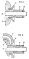
- FIG. 4 shows an enlarged detail of the switching flap 20 in a section along the axis of rotation of the switching flap.
- the Sealing hood 39 is conical. It is made of elastic Material, preferably made of an elastomer plastic.
- the sealing hood 39 can advantageously also be paraboloidal, be hemispherical or cylindrical.
- FIG. 5 shows a preferred embodiment of the switching flap 20 in one. Detail enlargement in a sectional view along the axis of rotation of the switching flap 20.
- the sealing hood 39 protrudes in the form of a bead over the sealing lip 37.
- Figure 6 is a sectional view taken along a section line III - III 'according to Figure 1.
- the first and second bearing bush 45, 46 are preferably made of bronze and a perfect fit for the first and second sleeves 24, 25.
- the switching flap is in figure 6 shown in their open state.
- the first and the second sealing hood 39, 40 are against the first and the second bearing bush 45, 46 pressed, however, due to their elasticity migrate outwards depending on the contact pressure. So an axial seal of the Switch flap causes around the bearing bush.
- the sealing hood 39, 40 dampens moreover caused by vibrations of the internal combustion engine and from the first or second bearing bush 45, 46 and the first and second sleeves 24, 25 generated Sounds.
- the sealing hood 39, 40 also dampens an overcurrent noise caused by the rattling of the switching flap 20 and pressure differences between the suction pipes 5, 6 is strongly induced. This is a major advantage there, the overcurrent noise audible as an unpleasant whistle will and increasingly strict legal regulations apply, the limit values for the amplitude of a motor vehicle define sound waves generated.
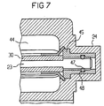
- FIG. 7 shows an enlarged detail of FIG. 6 in an alternative embodiment of the suction device.
- the shaft 23 is in the area in which it is in the bearing bush is mounted, designed to fit the bearing bush 45.
- the Damping means is designed as a damping ring 47, which in a groove 48 of the second bearing bush 45 is introduced.
- the wing flap can alternatively also have three or four arms.
- the invention is not restricted to the exemplary embodiments shown here.
Landscapes
- Engineering & Computer Science (AREA)
- Chemical & Material Sciences (AREA)
- Combustion & Propulsion (AREA)
- Mechanical Engineering (AREA)
- General Engineering & Computer Science (AREA)
- Characterised By The Charging Evacuation (AREA)
Description
- Figur 1
- eine Brennkraftmaschine,
- Figur 2
- einen Schnitt der Brennkraftmaschine gemäß Figur 1 längs der Schnittlinie II - II'
- Figur 3
- eine Schaltklappe,
- Figur 4
- eine Ausschnittsvergrößerung der Schaltklappe längs eines Schnittes entlang der Drehachse der Schaltklappe,
- Figur 5
- eine weitere Ausschnittsvergrößerung der Schaltklappe in einer Schnittbilddarstellung,
- Figur 6
- einen Schnitt längs einer Schnittlinie III - III' der Brennkraftmaschine gemäß Figur 1,
- Figur 7
- eine Ausschnittsvergrößerung der Ansaugeinrichtung.
Die Erfindung ist nicht auf die hier dargestellten Ausführungsbeispiele beschränkt.
Claims (7)
- Ansaugeinrichtung für eine Brennkraftmaschine mit:einem ersten Sammler (4), der über einen Ansaugstutzen (2) Umgebungsluft ansaugt,Saugrohren (5,6,7,8) , die von dem ersten Sammler (4) zu Einlässen der Zylinder (11, 12, 13, 14) der Brennkraftmaschine geführt sind, die in einem Abschnitt zwischen dem ersten Sammler (4) und den Zylindern (11, 12, 13, 14) eng aneinandergrenzen und die in ihrer Wandung einander zugewandte, aneinandergrenzende Öffnungen (44) aufweisen,mindestens einer Schaltklappe (20, 21, 22) mit einer Welle (23), undeiner Schalteinrichtung, die mittels der mindestens einen Schaltklappe (20, 21, 22) die Öffnungen (44) verschließt oder öffnet, dadurch gekennzeichnet, daß eine Lagerbuchse (44,45) vorgesehen ist, in der die Welle (23) gelagert ist und in die ein separates ringförmig ausgebildetes Dämpfungsmittel eingebracht ist.
- Ansaugeinrichtung nach Anspruch 1, dadurch gekennzeichnet, daß das Dämpfungsmittel auf der Welle angeordnet ist.
- Ansaugeinrichtung nach Anspruch 1 oder 2, dadurch gekennzeichnet, daß das Dämpfungsmittel aus einem Elastomer besteht.
- Ansaugeinrichtung nach einem der Ansprüche 1 bis 3, dadurch gekennzeichnet, daß die Schaltklappe (20, 21, 22) eine erste und eine zweite Dichthaube (39, 40) hat, die an den gegenüberliegenden axialen Enden der Schaltklappe (20, 21, 22) konzentrisch zu der Welle (23) angeordnet sind und die jeweils zu der Seite hin offen sind, die der Schaltklappe (20, 21, 22) abgewandt ist, und auf der Seite, die der Schaltklappe (20, 21, 22) zugewandt ist, mit der Schaltklappe (20, 21, 22) formschlüssig verbunden sind.
- Ansaugeinrichtung nach Anspruch 4, dadurch gekennzeichnet, daß die Schaltklappe (20, 21, 22) mit einer Dichtlippe (37) versehen ist, die randseitig an der Schaltklappe (20, 21, 22) angeordnet ist und einstückig mit der ersten und zweiten Dichthaube (39, 40) ausgebildet ist.
- Ansaugeinrichtung nach Anspruch 5, dadurch gekennzeichnet, daß die Dichthauben (39, 40) in Form einer Wulst über die Dichtlippe (37) hinausragen.
- Ansaugeinrichtung nach einem der Ansprüche 4 bis 6, dadurch gekennzeichnet, daß die erste und die zweite Dichthaube (39, 40) aus einem Elastomer bestehen.
Applications Claiming Priority (3)
| Application Number | Priority Date | Filing Date | Title |
|---|---|---|---|
| DE19717349A DE19717349A1 (de) | 1997-03-07 | 1997-04-24 | Ansaugeinrichtung |
| DE19717349 | 1997-04-24 | ||
| PCT/DE1998/000797 WO1998048154A1 (de) | 1997-04-24 | 1998-03-18 | Ansaugeinrichtung |
Publications (2)
| Publication Number | Publication Date |
|---|---|
| EP0977936A1 EP0977936A1 (de) | 2000-02-09 |
| EP0977936B1 true EP0977936B1 (de) | 2002-06-12 |
Family
ID=7827638
Family Applications (1)
| Application Number | Title | Priority Date | Filing Date |
|---|---|---|---|
| EP98925405A Expired - Lifetime EP0977936B1 (de) | 1997-04-24 | 1998-03-18 | Ansaugeinrichtung |
Country Status (4)
| Country | Link |
|---|---|
| US (1) | US6279528B1 (de) |
| EP (1) | EP0977936B1 (de) |
| HU (1) | HUP0003162A3 (de) |
| WO (1) | WO1998048154A1 (de) |
Families Citing this family (11)
| Publication number | Priority date | Publication date | Assignee | Title |
|---|---|---|---|---|
| CA2308632A1 (en) * | 1997-10-21 | 1999-04-29 | Filterwerk Mann & Hummel Gmbh | Drum controller |
| DE29916333U1 (de) * | 1999-09-16 | 2000-01-13 | Montaplast GmbH, 51597 Morsbach | Lagervorrichtung |
| DE19951082B4 (de) * | 1999-10-23 | 2013-05-29 | Mann + Hummel Gmbh | Saugrohr mit einer Schaltwalze |
| DE10303701B4 (de) * | 2003-01-30 | 2012-02-16 | Siemens Ag | Verfahren und Vorrichtung zum Steuern einer Brennkraftmaschine |
| US7191749B2 (en) * | 2003-07-07 | 2007-03-20 | Siemens Canada Limited | Laser welded intake manifold |
| US7455745B2 (en) * | 2005-06-03 | 2008-11-25 | Mahle International Gmbh | Laser welding of a plastic manifold |
| US7401590B2 (en) * | 2006-10-09 | 2008-07-22 | Harley-Davidson Motor Company Group, Inc. | Active air intake for an engine |
| PL2424754T3 (pl) | 2009-04-27 | 2015-04-30 | Fed Mogul Sa | Urządzenie wycieraczki do szyb pojazdu |
| US10428745B2 (en) * | 2013-02-19 | 2019-10-01 | Ford Global Technologies, Llc | Charge motion control valve and intake runner system |
| DE102016203517A1 (de) * | 2016-03-03 | 2017-09-07 | Mahle International Gmbh | Frischluftzuführungseinrichtung für eine Brennkraftmaschine eines Kraftfahrzeugs |
| JP6776715B2 (ja) * | 2016-08-09 | 2020-10-28 | アイシン精機株式会社 | 内燃機関の吸気装置 |
Family Cites Families (18)
| Publication number | Priority date | Publication date | Assignee | Title |
|---|---|---|---|---|
| US2570117A (en) * | 1946-01-31 | 1951-10-02 | Gen Electric | Shaft bearing |
| CH641259A5 (de) * | 1979-10-09 | 1984-02-15 | Fischer Ag Georg | Absperrklappe. |
| FR2505010B1 (fr) * | 1981-05-04 | 1985-06-14 | Valeo | Dispositif pour la commande d'un appareil de chauffage et de degivrage de vehicule automobile |
| US4803961A (en) * | 1985-11-19 | 1989-02-14 | Mazda Motor Corporation | Air suction devices for multicylinder engines |
| FR2613428B1 (fr) | 1987-03-30 | 1992-05-22 | Peugeot | Moteur alimente par injection, a circuit d'admission perfectionne |
| US4907547A (en) * | 1989-02-21 | 1990-03-13 | Siemens-Bendix Automotive Electronics L.P. | One-piece wave deflector for I.C. engine intake system |
| FR2650340B1 (fr) * | 1989-07-26 | 1994-04-29 | Solex | Dispositif d'etranglement a organe rotatif pour installation d'alimentation de moteur a combustion interne |
| DE4041786C2 (de) | 1990-12-24 | 2003-04-30 | Opel Adam Ag | Für eine Brennkraftmaschine bestimmte Ansauganlage |
| JP2612099B2 (ja) * | 1991-01-29 | 1997-05-21 | 株式会社日立製作所 | 絞り弁組立体 |
| DE4228334A1 (de) * | 1992-08-26 | 1994-03-03 | Audi Ag | Saugrohranlage für eine Mehrzylinder-Brennkraftmaschine |
| US5348272A (en) * | 1993-03-31 | 1994-09-20 | Combustion Engineering, Inc. | Damper with improved drive shaft bearing assembly |
| DE4333676A1 (de) * | 1993-10-02 | 1995-04-06 | Bosch Gmbh Robert | Betätigungsvorrichtung für ein Drosselorgan |
| DE4337975A1 (de) * | 1993-11-06 | 1995-05-11 | Neumo Gmbh | Gehäuse-Dichtungsanordnung für Fluidgehäuse, insbesondere Flanschverbindungen |
| DE4499626T1 (de) * | 1993-12-10 | 1996-02-22 | Mitsubishi Motors Corp | Ansaugsteuervorrichtung für einen Mehrzylinder-Verbrennungsmotor |
| WO1996007022A1 (de) * | 1994-08-31 | 1996-03-07 | Siemens Aktiengesellschaft | Variable luftansaugvorrichtung |
| FR2724418B1 (fr) * | 1994-09-09 | 1997-01-17 | Magneti Marelli France | Tubulure d'admission d'air a volets pivotants pour moteur a combustion interne |
| DE19510622A1 (de) * | 1995-03-23 | 1996-09-26 | Bosch Gmbh Robert | Drosselvorrichtung und Verfahren zur Herstellung einer Drosselvorrichtung |
| DE19545746C1 (de) * | 1995-12-07 | 1997-06-12 | Siemens Ag | Luftansaugvorrichtung für eine Brennkraftmaschine |
-
1998
- 1998-03-18 EP EP98925405A patent/EP0977936B1/de not_active Expired - Lifetime
- 1998-03-18 WO PCT/DE1998/000797 patent/WO1998048154A1/de not_active Ceased
- 1998-03-18 HU HU0003162A patent/HUP0003162A3/hu unknown
-
1999
- 1999-10-25 US US09/426,423 patent/US6279528B1/en not_active Expired - Fee Related
Also Published As
| Publication number | Publication date |
|---|---|
| EP0977936A1 (de) | 2000-02-09 |
| US6279528B1 (en) | 2001-08-28 |
| HUP0003162A3 (en) | 2001-05-28 |
| HUP0003162A2 (hu) | 2001-02-28 |
| WO1998048154A1 (de) | 1998-10-29 |
Similar Documents
| Publication | Publication Date | Title |
|---|---|---|
| EP0726388B1 (de) | Ansaugsystem | |
| EP1651898B1 (de) | Rohr zur führung von gas bzw. flüssigkeit | |
| WO1995006808A1 (de) | Drosseleinrichtung | |
| DE10026355B4 (de) | Schalldämpfende Luftleitung | |
| EP2677155B1 (de) | Klappenvorrichtung und Sauganlage | |
| EP0977936A1 (de) | Ansaugeinrichtung | |
| EP0964987B1 (de) | Verfahren zum herstellen einer schaltklappe | |
| EP0970301A1 (de) | Schaltwalze, insbesondere zur verwendung in einer saugrohranlage für eine mehrzylinder-brennkraftmaschine | |
| EP1200722B1 (de) | Drosseleinrichtung mit einer klappe zum einbau in eine flanschverbindung | |
| DE102005031129A1 (de) | Einlasssteuervorrichtung für eine Brennkraftmaschine | |
| EP0891486B1 (de) | Ansaugsystem für einen verbrennungsmotor | |
| DE202007013151U1 (de) | Ansaugsystem für eine Brennkraftmaschine | |
| DE10204768B4 (de) | Drallverstellbarer Einlasskanal mit zumindest einer in Längsrichtung verlaufenden Trennwand | |
| EP1299627B1 (de) | Schaltklappe | |
| EP0733790B1 (de) | Verstelleinrichtung | |
| DE10219268C1 (de) | Drosselklappeneinheit | |
| DE19819364B4 (de) | Drosselklappe | |
| EP0688943A1 (de) | Luftansaugeanlage einer mehrzylindrigen Brennkraftmaschine | |
| DE19931934C2 (de) | Resonator zur Verringerung von Schwingungen in Luftleitung | |
| EP0868598B1 (de) | Luftansaugvorrichtung mit variabler saugrohrlänge für eine brennkraftmaschine | |
| DE10236393A1 (de) | Ansaugkanalsystem | |
| DE10303701B4 (de) | Verfahren und Vorrichtung zum Steuern einer Brennkraftmaschine | |
| DE102009043627A1 (de) | Ansaugeinrichtung für Verbrennungsmotoren | |
| EP1226377A1 (de) | Klappenventil mit dünnwandiger rohrabdichtung | |
| DE102005029798B4 (de) | Schaltbauteil für ein Saugrohr einer Brennkraftmaschine |
Legal Events
| Date | Code | Title | Description |
|---|---|---|---|
| PUAI | Public reference made under article 153(3) epc to a published international application that has entered the european phase |
Free format text: ORIGINAL CODE: 0009012 |
|
| 17P | Request for examination filed |
Effective date: 19991019 |
|
| AK | Designated contracting states |
Kind code of ref document: A1 Designated state(s): DE FR GB IT |
|
| 17Q | First examination report despatched |
Effective date: 20010528 |
|
| GRAG | Despatch of communication of intention to grant |
Free format text: ORIGINAL CODE: EPIDOS AGRA |
|
| GRAG | Despatch of communication of intention to grant |
Free format text: ORIGINAL CODE: EPIDOS AGRA |
|
| GRAH | Despatch of communication of intention to grant a patent |
Free format text: ORIGINAL CODE: EPIDOS IGRA |
|
| GRAH | Despatch of communication of intention to grant a patent |
Free format text: ORIGINAL CODE: EPIDOS IGRA |
|
| GRAA | (expected) grant |
Free format text: ORIGINAL CODE: 0009210 |
|
| AK | Designated contracting states |
Kind code of ref document: B1 Designated state(s): DE FR GB IT |
|
| REG | Reference to a national code |
Ref country code: GB Ref legal event code: FG4D Free format text: NOT ENGLISH |
|
| REF | Corresponds to: |
Ref document number: 59804430 Country of ref document: DE Date of ref document: 20020718 |
|
| ET | Fr: translation filed | ||
| PLBE | No opposition filed within time limit |
Free format text: ORIGINAL CODE: 0009261 |
|
| STAA | Information on the status of an ep patent application or granted ep patent |
Free format text: STATUS: NO OPPOSITION FILED WITHIN TIME LIMIT |
|
| 26N | No opposition filed |
Effective date: 20030313 |
|
| PGFP | Annual fee paid to national office [announced via postgrant information from national office to epo] |
Ref country code: GB Payment date: 20050303 Year of fee payment: 8 |
|
| PGFP | Annual fee paid to national office [announced via postgrant information from national office to epo] |
Ref country code: FR Payment date: 20050331 Year of fee payment: 8 |
|
| PGFP | Annual fee paid to national office [announced via postgrant information from national office to epo] |
Ref country code: DE Payment date: 20050519 Year of fee payment: 8 |
|
| PG25 | Lapsed in a contracting state [announced via postgrant information from national office to epo] |
Ref country code: GB Free format text: LAPSE BECAUSE OF NON-PAYMENT OF DUE FEES Effective date: 20060318 |
|
| PGFP | Annual fee paid to national office [announced via postgrant information from national office to epo] |
Ref country code: IT Payment date: 20060331 Year of fee payment: 9 |
|
| PG25 | Lapsed in a contracting state [announced via postgrant information from national office to epo] |
Ref country code: DE Free format text: LAPSE BECAUSE OF NON-PAYMENT OF DUE FEES Effective date: 20061003 |
|
| GBPC | Gb: european patent ceased through non-payment of renewal fee |
Effective date: 20060318 |
|
| REG | Reference to a national code |
Ref country code: FR Ref legal event code: ST Effective date: 20061130 |
|
| PG25 | Lapsed in a contracting state [announced via postgrant information from national office to epo] |
Ref country code: FR Free format text: LAPSE BECAUSE OF NON-PAYMENT OF DUE FEES Effective date: 20060331 |
|
| PG25 | Lapsed in a contracting state [announced via postgrant information from national office to epo] |
Ref country code: IT Free format text: LAPSE BECAUSE OF NON-PAYMENT OF DUE FEES Effective date: 20070318 |