EP0977337A2 - Circuit for measuring and limiting currents in converters for supplying motors - Google Patents
Circuit for measuring and limiting currents in converters for supplying motors Download PDFInfo
- Publication number
- EP0977337A2 EP0977337A2 EP99113966A EP99113966A EP0977337A2 EP 0977337 A2 EP0977337 A2 EP 0977337A2 EP 99113966 A EP99113966 A EP 99113966A EP 99113966 A EP99113966 A EP 99113966A EP 0977337 A2 EP0977337 A2 EP 0977337A2
- Authority
- EP
- European Patent Office
- Prior art keywords
- current
- capacitor
- circuit
- converter
- intermediate circuit
- Prior art date
- Legal status (The legal status is an assumption and is not a legal conclusion. Google has not performed a legal analysis and makes no representation as to the accuracy of the status listed.)
- Granted
Links
Images

Classifications
-
- H—ELECTRICITY
- H02—GENERATION; CONVERSION OR DISTRIBUTION OF ELECTRIC POWER
- H02M—APPARATUS FOR CONVERSION BETWEEN AC AND AC, BETWEEN AC AND DC, OR BETWEEN DC AND DC, AND FOR USE WITH MAINS OR SIMILAR POWER SUPPLY SYSTEMS; CONVERSION OF DC OR AC INPUT POWER INTO SURGE OUTPUT POWER; CONTROL OR REGULATION THEREOF
- H02M1/00—Details of apparatus for conversion
- H02M1/42—Circuits or arrangements for compensating for or adjusting power factor in converters or inverters
- H02M1/4208—Arrangements for improving power factor of AC input
- H02M1/4225—Arrangements for improving power factor of AC input using a non-isolated boost converter
-
- H—ELECTRICITY
- H02—GENERATION; CONVERSION OR DISTRIBUTION OF ELECTRIC POWER
- H02M—APPARATUS FOR CONVERSION BETWEEN AC AND AC, BETWEEN AC AND DC, OR BETWEEN DC AND DC, AND FOR USE WITH MAINS OR SIMILAR POWER SUPPLY SYSTEMS; CONVERSION OF DC OR AC INPUT POWER INTO SURGE OUTPUT POWER; CONTROL OR REGULATION THEREOF
- H02M5/00—Conversion of ac power input into ac power output, e.g. for change of voltage, for change of frequency, for change of number of phases
- H02M5/40—Conversion of ac power input into ac power output, e.g. for change of voltage, for change of frequency, for change of number of phases with intermediate conversion into dc
- H02M5/42—Conversion of ac power input into ac power output, e.g. for change of voltage, for change of frequency, for change of number of phases with intermediate conversion into dc by static converters
- H02M5/44—Conversion of ac power input into ac power output, e.g. for change of voltage, for change of frequency, for change of number of phases with intermediate conversion into dc by static converters using discharge tubes or semiconductor devices to convert the intermediate dc into ac
- H02M5/453—Conversion of ac power input into ac power output, e.g. for change of voltage, for change of frequency, for change of number of phases with intermediate conversion into dc by static converters using discharge tubes or semiconductor devices to convert the intermediate dc into ac using devices of a triode or transistor type requiring continuous application of a control signal
- H02M5/458—Conversion of ac power input into ac power output, e.g. for change of voltage, for change of frequency, for change of number of phases with intermediate conversion into dc by static converters using discharge tubes or semiconductor devices to convert the intermediate dc into ac using devices of a triode or transistor type requiring continuous application of a control signal using semiconductor devices only
-
- H—ELECTRICITY
- H02—GENERATION; CONVERSION OR DISTRIBUTION OF ELECTRIC POWER
- H02P—CONTROL OR REGULATION OF ELECTRIC MOTORS, ELECTRIC GENERATORS OR DYNAMO-ELECTRIC CONVERTERS; CONTROLLING TRANSFORMERS, REACTORS OR CHOKE COILS
- H02P21/00—Arrangements or methods for the control of electric machines by vector control, e.g. by control of field orientation
- H02P21/22—Current control, e.g. using a current control loop
-
- G—PHYSICS
- G01—MEASURING; TESTING
- G01R—MEASURING ELECTRIC VARIABLES; MEASURING MAGNETIC VARIABLES
- G01R19/00—Arrangements for measuring currents or voltages or for indicating presence or sign thereof
- G01R19/0092—Arrangements for measuring currents or voltages or for indicating presence or sign thereof measuring current only
-
- H—ELECTRICITY
- H02—GENERATION; CONVERSION OR DISTRIBUTION OF ELECTRIC POWER
- H02M—APPARATUS FOR CONVERSION BETWEEN AC AND AC, BETWEEN AC AND DC, OR BETWEEN DC AND DC, AND FOR USE WITH MAINS OR SIMILAR POWER SUPPLY SYSTEMS; CONVERSION OF DC OR AC INPUT POWER INTO SURGE OUTPUT POWER; CONTROL OR REGULATION THEREOF
- H02M1/00—Details of apparatus for conversion
- H02M1/0003—Details of control, feedback or regulation circuits
- H02M1/0009—Devices or circuits for detecting current in a converter
-
- H—ELECTRICITY
- H02—GENERATION; CONVERSION OR DISTRIBUTION OF ELECTRIC POWER
- H02M—APPARATUS FOR CONVERSION BETWEEN AC AND AC, BETWEEN AC AND DC, OR BETWEEN DC AND DC, AND FOR USE WITH MAINS OR SIMILAR POWER SUPPLY SYSTEMS; CONVERSION OF DC OR AC INPUT POWER INTO SURGE OUTPUT POWER; CONTROL OR REGULATION THEREOF
- H02M1/00—Details of apparatus for conversion
- H02M1/0067—Converter structures employing plural converter units, other than for parallel operation of the units on a single load
- H02M1/007—Plural converter units in cascade
-
- Y—GENERAL TAGGING OF NEW TECHNOLOGICAL DEVELOPMENTS; GENERAL TAGGING OF CROSS-SECTIONAL TECHNOLOGIES SPANNING OVER SEVERAL SECTIONS OF THE IPC; TECHNICAL SUBJECTS COVERED BY FORMER USPC CROSS-REFERENCE ART COLLECTIONS [XRACs] AND DIGESTS
- Y02—TECHNOLOGIES OR APPLICATIONS FOR MITIGATION OR ADAPTATION AGAINST CLIMATE CHANGE
- Y02B—CLIMATE CHANGE MITIGATION TECHNOLOGIES RELATED TO BUILDINGS, e.g. HOUSING, HOUSE APPLIANCES OR RELATED END-USER APPLICATIONS
- Y02B70/00—Technologies for an efficient end-user side electric power management and consumption
- Y02B70/10—Technologies improving the efficiency by using switched-mode power supplies [SMPS], i.e. efficient power electronics conversion e.g. power factor correction or reduction of losses in power supplies or efficient standby modes
Abstract
Description
Die vorliegende Erfindung betrifft eine Schaltungsanordnung mit darauf aufbauendem
Verfahren zur Messung der Ströme eines aus einem Spannungszwischenkreis
gespeisten Umrichter zur Ansteuerung von Motoren, bei der mit einem Meßmittel
zur Strommessung sowohl die Phasenströme des Motors als auch die Stromaufnahme
aus dem Netz gemessen werden können nach Anspruch 1, sowie eine
Schaltungsanordnung zur Einschaltstrombegrenzung nach Anspruch 2.The present invention relates to a circuit arrangement based thereon
Method for measuring the currents from a voltage intermediate circuit
powered converter for controlling motors with a measuring device
for current measurement, both the phase currents of the motor and the current consumption
can be measured from the network according to
Um aus einem Umrichter gespeiste Motoren, wie Asynchronmotoren oder Synchronmotoren, unter allen Betriebsbedingungen, wie beispielsweise Drehmoment, Drehzahl und Motortemperatur, elektrisch so zu speisen, daß der Motor mit dem höchstmöglichen Wirkungsgrad betrieben wird, ist es erforderlich, daß die elektrische Steuerung zur Speisung des Motors als Reglereingangsgröße auch über die Meßgröße der Phasenströme des Motors verfügt. Hierdurch kann dann zum Beispiel auch eine feldorientierte Regelung des Motors implementiert werden.To motors fed from a converter, such as asynchronous motors or synchronous motors, under all operating conditions, such as torque, Speed and engine temperature to feed electrically so that the engine with the operating the highest possible efficiency, it is necessary that the electrical Control for feeding the motor as a controller input variable also via the Measured variable of the phase currents of the motor. This can then, for example field-oriented control of the motor can also be implemented.
Eine Schaltungsanordnung zur aktiven Leistungsfaktorkorrektur (PFC), d.h. zur
gesteuerten Stromaufnahme aus dem Netz nach Stand der Technik ist z.B. auf
Seite 49, Bild 1, in Heft 23/1996 der Zeitschrift "ELEKTRONIK", Franzis-Verlag,
veröffentlicht. Der entsprechende Strommeßwiderstand zur Messung der Netzstromaufnahme
befindet sich dort in der Netzzuleitung.A circuit arrangement for active power factor correction (PFC), i.e. to
Controlled current consumption from the network according to the prior art is e.g. on
Page 49,
Schaltungsanordnungen zur Einschaltstrombegrenzung nach Stand der Technik sind z.B. im Datenbuch: Heißleiter, Siemens Matsushita Components, 1996, Seite 36, Bild 10 oder im Datenbuch von Thomson-CSF LCC, 1994, Seite 28, Bild 16 zu entnehmen. Diesen Schaltungsanordnungen ist gemeinsam, daß ein temperaturabhängiger Widerstand (NTC) in der Netzzuleitung zum Zwischenkreis den Einschaltstrom bei Zuschaltung der Elektronik mit entladenen Zwischenkreiskondensator an das Netz begrenzt.Circuit arrangements for inrush current limitation according to the prior art are e.g. in the data book: thermistor, Siemens Matsushita Components, 1996, page 36, Figure 10 or in the Thomson-CSF LCC data book, 1994, page 28, Figure 16 refer to. Common to these circuit arrangements is that they are temperature-dependent Resistor (NTC) in the supply line to the DC link the inrush current when switching on the electronics with discharged DC link capacitor limited to the network.
Eine herkömmliche Schaltungsanordnung zur Messung der Phasenströme eines aus
einem 6-pulsigen Umrichter gespeisten dreiphasigen Motors, die z.B. aus den
nachfolgend aufgeführten Publikationen bekannt ist, ist beispielhaft in den Figuren
5 und 6 gezeigt. In Figur 5 ist zunächst schematisch die vereinfachte Topologie
eines aus einem Spannungszwischenkreis 4 gespeisten Umrichters 5 zur Speisung
eines dreiphasigen Motors 1 dargestellt. Die Nachladeeinrichtung für den Zwischenkreiskondensator
10 des Spannungszwischenkreises 4 besteht zum Beispiel
aus einer am Niederspannungsnetz 2 angeschlossenen Gleichrichterbrücke 3. Der
6-pulsige Umrichter 5 weist drei obere Schaltmittel 6a, 7a, 8a und drei unter
Schaltmittel 6b, 7b, 8b auf, welche beispielsweise durch Leistungstransistoren realisiert
sind. Die Schaltmittel 6-8 bilden dabei drei Schaltmittel-Halbbrücken 6a-6b,
7a-7b und 8a-8b, die jeweils invers angesteuert werden, so daß - bei Vernachlässigung
der Schalttotzeiten - von jeder Halbbrücke zu jedem Zeitpunkt jeweils ein
Schaltmittel geöffnet und das entsprechende andere Schaltmittel geschlossen ist.A conventional circuit arrangement for measuring the phase currents
a 6-pulse converter fed three-phase motor, which e.g. from the
publications listed below is known, is exemplary in the figures
5 and 6. The simplified topology is shown schematically in FIG
a
Zwischen Spannungszwischenkreis 4 und Umrichter 5 ist wahlweise ein Mittel 9
oder 9' zur Strommessung geschaltet, welches der Messung des Umrichterstromes
Idc bzw. alternativ Idc' im Spannungszwischenkreis 4 dient. Nach dem in Figur 5
veranschaulichten Stand der Technik erfolgt die Strommessung im Spannungszwischenkreis
4 in einem Strompfad, in dem ausschließlich der Umrichterstrom Idc,
Idc' fließt.A
In der Publikation "Deviation of Motor Line-Current Waveforms from the DC-Link
Current of an Inverter" von T.C. Green und B.W. Williams, IEE Proceedings
Part B, Vol. 136, No. 4, Juli 1989, Seiten 196 - 204, wird beschrieben, wie durch
die Messung des Umrichterstromes Idc im Spannungszwischenkreis 4 und dessen
Zuordnung zu den Schaltzuständen der Schaltmittel 6-8 des Umrichters 5 die Phasenströme
des Motors 1 rekonstruiert werden können. Als kostengünstigste Lösung
für das Strommeßmittel 9, 9' wird dort ein Meßwiderstand mit Signalverstärkung
mittels schnellem Operationsverstärker im Spannungszwischenkreis 4 vorgeschlagen,
wobei der Meßwiderstand in einem Strompfad vorgesehen ist, in dem
ausschließlich der Umrichterstrom Idc fließt (siehe Figur 2, Seite 197 dieser Veröffentlichung).In the publication "Deviation of Motor Line-Current Waveforms from the DC-Link
Current of an Inverter "by T.C. Green and B.W. Williams, IEE Proceedings
Part B, Vol. 136, No. 4, July 1989, pages 196-204, is described as by
the measurement of the converter current Idc in the voltage
Weiter wird auch in der Publikation "Phase Current Reconstruction of a Three-Phase
Voltage Source Inverter Fed Drive Using a Sensor in the DC-Link" von M.
Riese von der Technischen Universität Dresden, Intelligent Motion '96 - Mai,
Proceedings, CD-Version, Seiten 95-102, ein Verfahren zur Rekonstruktion der
Phasenströme eines dreiphasigen Motors erläutert. Hier werden die Phasenströme
des Motors ebenfalls aus einer Strommessung in einem Pfad des Spannungszwischenkreises
abgeleitet, in dem ausschließlich der Umrichterstrom fließt (siehe
Picture 1 der Veröffentlichung).The publication "Phase Current Reconstruction of a Three-Phase
Voltage Source Inverter Fed Drive Using a Sensor in the DC-Link "from M.
Giant from the Technical University of Dresden, Intelligent Motion '96 - May,
Proceedings, CD version, pages 95-102, a procedure for the reconstruction of the
Phase currents of a three-phase motor explained. Here are the phase currents
of the motor also from a current measurement in a path of the voltage intermediate circuit
derived in which only the converter current flows (see
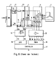
In Figur 6 ist nun die vollständige Topologie der in Figur 5 dargestellten herkömmlichen
Elektronik veranschaulicht. Ganz links in Figur 6 ist die Gleichrichterbrücke
3 zur Gleichrichtung der Wechselspannung bei Speisung der Elektronik aus
dem Niederspannungsnetz 2 gezeigt. Der positive Ausgang der Gleichrichterbrücke
3 ist mit einem Einschaltstrombegrenzer 11 verbunden, der zum Beispiel aus einem
NTC-Widerstand 12 zur Begrenzung der Stromaufnahme der angeschlossenen
Elektronik bei Netzzuschaltung bei entladenem Zwischenkreiskondensator 10 besteht.
An die Gleichrichterbrücke 3 ist ferner eine Einrichtung 13 zur aktiven
Steuerung der Stromaufnahme auf dem Netz 2 zur Leistungsfaktorkorrektur (PFC)
in der Topologie eines Hochsetzstellers angeschlossen. Der gezeigte Hochsetzsteller
13 weist zudem ein Mittel 14 zur Messung des Netzstromes in Form eines
Meßwiderstandes auf. Dieser Meßwiderstand 14 kann allerdings nicht so groß gewählt
werden, daß der Einschaltstrombegrenzer 11 entfallen könnte, da die Verlustleistung
bei Einsatz eines geeigneten Festwiderstandes in der Netzzuleitung zu
groß wäre. In Figure 6 is the complete topology of the conventional shown in Figure 5
Electronics illustrated. At the far left in Figure 6 is the
An den Hochsetzsteller 13 schließt sich der schon anhand von Figur 5 erläuterter
Spannungszwischenkreis 4 mit beispielsweise einem Hochspannungs-Elektrolyt-Kondensator
10 an. Das Strommeßmittel 9 ist in einem Strompfad des Spannungszwischenkreises
4 angeordnet, in dem ausschließlich der Umrichterstrom Idc fließt.
Der Spannungszwischenkreis 4 speist den Umrichter 5, der als 6-pulsige Brücke
für den dreiphasigen Motor 1 ausgebildet ist. Als Schaltmittel 6-8 des Umrichters 5
werden nach dem Stand der Technik zum Beispiel Leistungstransistoren, wie
IGBT's, mit antiparallel geschalteten Freilaufdioden eingesetzt.The step-
Ein analoger Treiberbaustein 15 verstärkt die an den beiden Meßwiderständen 9
und 14 abgegriffenen Meßsignale so, daß die Meßsignale Im (Netzstrom) und Idc
(Umrichterstrom) durch einen Analog/Digital-Wandler 16 einer Steuervorrichtung
17, wie beispielsweise eines Microcontrollers, mit ausreichender Auflösung ausgewertet
werden können. Der Microcontroller 17 steuert und regelt sowohl den
Motor 1 über die Schaltmittel 6-8 des Umrichters 5 als auch die Stromaufnahme
aus dem Niederspannungsnetz 2 über das Schaltmittel 18 des Hochsetzstellers 13.
Die Schaltmittel 6-8 und 18 werden dabei beispielsweise von einer PWM-(Pulsbreiten-Modulations-)Einheit
19 mit Hilfe eines digitalen Leistungstreiberbausteines
20 gesteuert.An
Ausgehend von dem oben anhand der Figuren 5 und 6 beschriebenen Stand der Technik ist es Aufgabe der vorliegenden Erfindung, eine Vorrichtung zur Messung der Ströme eines aus einem Umrichter gespeisten Motors vorzuschlagen, welche nicht nur die Messung der Motorströme ermöglicht, sondern mit der auch die Netzstromaufnahme gemessen und begrenzt werden kann.Starting from the state of the art described above with reference to FIGS Technology is the object of the present invention, a device for measurement to propose the currents of a motor fed from a converter, which not only enables the measurement of the motor currents, but also with that Mains current consumption can be measured and limited.
Diese Aufgabe wird durch eine Schaltungsanordnung mit den Merkmalen von Anspruch
1 bzw. Anspruch 2 gelöst.This object is achieved by a circuit arrangement with the features of
Die Messung des Stromes in einem Strompfad, in dem ausschließlich der Strom Icap der Kapazität des Spannungszwischenkreises fließt, hat gegenüber der Messung des Umrichterstromes Idc verschiedene Vorteile. Es kann mit dem Strommeßmittel neben der Strommessung der Phasenströme des Motors auch der aufgenommene Netzstrom gemessen werden, was zumindest bei einer aktiven Steuerung der Stromaufnahme aus dem Netz notwendig ist, so daß im Gegensatz zu der herkömmlichen Schaltungsanordnung kein zweites Strommeßmittel für die Messung des Netzstromes eingesetzt werden muß. Durch die erfindungsgemäße Anordnung des Strommeßmittels wird somit die Schaltungsanordnung vereinfacht und demnach auch kostengünstiger.Measuring the current in a current path in which only the current Icap the capacitance of the voltage intermediate circuit flows compared to the measurement of the converter current Idc various advantages. It can with the current measuring device in addition to the current measurement of the phase currents of the motor also the recorded one Mains current can be measured, which is at least with an active control the power consumption from the network is necessary, so that in contrast to the conventional Circuit arrangement no second current measuring means for the measurement of the mains current must be used. Through the arrangement according to the invention of the current measuring means, the circuit arrangement is thus simplified and accordingly also cheaper.
Ein weiterer wesentlicher Vorteil der erfindungsgemäßen Schaltungsanordnung besteht darin, daß das Strommeßmittel zur Messung des Stromes Icap in der Kapazität des Spannungszwischenkreises gleichzeitig als Einschaltstrombegrenzer bei entladenem Zwischenkreiskondensator wirkt, wenn das Strommeßmittel in Form eines elektrischen Widerstandes ausgebildet ist. Hierdurch ist es möglich, auf einen zusätzlichen Widerstand zur Einschaltstrombegrenzung am Ausgang der Gleichrichterbrücke zu verzichten. Wenn sich gemäß der erfindungsgemäßen Schaltungsanordnung der Widerstand zur Einschaltstrombegrenzung also nicht in der Netzzuleitung, sondern in Reihe mit dem Zwischenkreiskondensator befindet, wo die effektive Strombelastung typisch um den Faktor 2 geringer ist, womit sich die Verlustleistung am Einschaltstrombegrenzer bei gleichem Widerstandswert etwa auf ¼ gegenüber der herkömmlichen Anordnung reduziert, kann beispielsweise anstelle eines teureren temperaturabhängigen Widerstandes ein Festwiderstand verwendet werden.Another significant advantage of the circuit arrangement according to the invention is that the current measuring means for measuring the current Icap in the capacitance of the voltage intermediate circuit simultaneously as an inrush current limiter discharged intermediate circuit capacitor acts when the current measuring means is in shape an electrical resistance is formed. This makes it possible to click on one additional resistance for inrush current limitation at the output of the rectifier bridge to renounce. If according to the circuit arrangement according to the invention the resistance to the inrush current limitation is not in the mains supply, but is in series with the DC link capacitor where the effective Current load is typically lower by a factor of 2, which reduces the power loss at the inrush current limiter with the same resistance value approximately to ¼ reduced compared to the conventional arrangement, for example instead of a more expensive temperature-dependent resistor uses a fixed resistor become.
Weitere Ausgestaltungen und Weiterbildungen der vorliegenden Erfindung sind Gegenstand der Unteransprüche.Further refinements and developments of the present invention are Subject of the subclaims.
Die Erfindung wird im folgenden anhand eines bevorzugten Ausführungsbeispieles unter Bezugnahme auf die beiliegende Zeichnung näher erläutert. Darin zeigen:
Figur 1- schematisch die vereinfachte Topologie eines aus einem Umrichter gespeisten mehrphasigen Motors gemäß der vorliegenden Erfindung;
Figur 2- die Schaltungsanordnung von
Figur 1 zusätzlich mit einem Mittel zur aktiven Steuerung der Stromaufnahme aus dem Netz (PFC); Figur 3- schematisch die vollständige Topologie eines aus einem Umrichter gespeisten mehrphasigen Motors gemäß der vorliegenden Erfindung;
Figur 4- eine Tabelle der möglichen Schaltzustände der Schaltmittel und des zugehörigen
gemessenen Stromes der Schaltungsanordnung von
Figur 2 bzw. 3; Figur 5- schematisch die vereinfachte Topologie eines herkömmlichen aus einem Umrichter gespeisten mehrphasigen Motors; und
Figur 6- schematisch die vollständige Topologie eines aus einem Umrichter gespeisten mehrphasigen Motors nach dem Stand der Technik.
- Figure 1
- schematically the simplified topology of a multi-phase motor fed from a converter according to the present invention;
- Figure 2
- the circuit arrangement of Figure 1 additionally with a means for actively controlling the power consumption from the network (PFC);
- Figure 3
- schematically the complete topology of a multi-phase motor fed from a converter according to the present invention;
- Figure 4
- a table of the possible switching states of the switching means and the associated measured current of the circuit arrangement of Figures 2 and 3;
- Figure 5
- schematically the simplified topology of a conventional multi-phase motor fed from a converter; and
- Figure 6
- schematically the complete topology of a multi-phase motor fed from a converter according to the prior art.
In Figur 1 ist zunächst eine vereinfachte Schaltungsanordnung zur erfindungsgemäßen
Messung der Phasenströme Iu, Iv, Iw eines dreiphasigen Motors 1 dargestellt,
der von einem 6-pulsigen Umrichter 5 betrieben wird. Der Umrichter 5 seinerseits
wird aus einem Spannungszwischenkreis 4 gespeist, der im wesentlichen
aus einem Zwischenkreiskondensator 10, vorzugsweise einem Hochspannungs-Elektrolyt-Kondensator,
aufgebaut ist. Die Nachladeeinrichtung für den Zwischenkreiskondensator
10 des Spannungszwischenkreises 4 besteht aus einer am Niederspannungsnetz
2 angeschlossenen Gleichrichterbrücke 3 bekannter Art.In Figure 1 is first a simplified circuit arrangement for the invention
Measurement of the phase currents Iu, Iv, Iw of a three-
Der 6-pulsige Umrichter 5 weist drei obere Schaltmittel 6a, 7a, 8a und drei unter
Schaltmittel 6b, 7b und 8b auf, welche vorzugsweise durch Leistungstransistoren,
wie beispielsweise IGBT's, mit antiparallel geschalteten Freilaufdioden realisiert
sind. Die Schaltmittel 6-8 sind dabei als drei Schaltmittel-Halbbrücken 6a-6b, 7a-7b
und 8a-8b geschaltet, die jeweils invers angesteuert werden, d.h. wenn das obere
Schaltmittel 6a, 7a, 8a geschlossen ist, ist - bei Vernachlässigung der in der
Praxis auftretenden Schalttotzeiten - das entsprechende untere Schaltmittel 6b, 7b
und 8b geöffnet und umgekehrt.The 6-
Zur Messung der Phasenströme Iu, Iv, Iw des Motors 1 ist ein Mittel 21 bzw. 21'
zur Strommessung vorgesehen, welches in einem Strompfad angeordnet ist, in dem
ausschließlich der Strom Icap bzw. Icap' der Kapazität 10 des Spannungszwischenkreises
4 - im folgenden nur kurz Kondensatorstrom Icap bezeichnet - fließt.
Vorzugsweise ist das Mittel 21, 21' zur Strommessung direkt in Reihe mit dem
Zwischenkreiskondensator 10 geschaltet. Die in Figur 1 gezeigten Strommeßmittel
21 und 21' werden alternativ verwendet. Als Strommeßmittel 21, 21' eignen sich
beispielsweise einfache Meßwiderstände.A means 21 or 21 'is used to measure the phase currents Iu, Iv, Iw of the
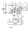
In Figur 2 ist die Schaltungsanordnung von Figur 1 dargestellt, welche um einen
sogenannten Hochsetzsteller 13 zur Leistungsfaktorkorrektur (PFC) erweitert ist.
In dieser Schaltungsanordnung wirkt sich die erfindungsgemäße Anordnung des
Strommeßmittels 21 besonders günstig aus.In Figure 2, the circuit arrangement of Figure 1 is shown, which by one
so-called step-up
Zwischen den Spannungszwischenkreis 4 und der Gleichrichterbrücke 3 ist ein
Mittel zur aktiven Steuerung der Stromaufnahme aus dem Niederspannungsnetz 2
geschaltet, das in der Topologie eines Hochsetzstellers 13 dargestellt ist. Ein solcher
Hochsetzsteller dient der Leistungsfaktorkorrektur (PFC) zur Einhaltung entsprechender
EMV-Vorschriften bezüglich Netzoberwellen. Der Hochsetzsteller 13
weist, parallel zu dem Zwischenkreiskondensator 10 geschaltet, ein Schaltmittel 18
auf, welches - wie die Schaltmittel 6-8 des Umrichters 5 - von einer in Figur 2 nicht
gezeigten Steuervorrichtung 17 gesteuert wird, um die Stromaufnahme der Schaltungsanordnung
zu steuern. In diesem Fall hängt der momentane Strom Icap im
Zwischenkreiskondensator 10 zusätzlich noch von dem momentanen Schaltzustand
des Schaltmittels 18 ab.Between the voltage
Mit Hilfe dieses Hochsetzstellers 13 kann die Wechselstrombelastung für den Zwischenkreiskondensator
10 des Spannungszwischenkreises 4 maßgeblich reduziert
werden, da die Stromaufnahme aus dem Netz 2 dem vom Umrichter 5 angeforderten
Strom angenähert werden kann. Hierdurch ist es möglich, das Strommeßmittel
21 des Kondensatorstromes Icap als einfachen induktionsarmen Festwiderstand
auszubilden. Dieses wirkt vorzugsweise zugleich als Mittel zur Einschaltstrombegrenzung
bei Zuschaltung des Umrichters 5 mit entladendem Zwischenkreiskondensator
10 an das Netz 2, so daß bei der erfindungsgemäßen Anordnung des
Strommeßmittels 21 auf einen zusätzlichen Widerstand zur Einschaltstrombegrenzung
am Ausgang der Gleichrichterbrücke 3 verzichtet werden kann. With the help of this step-up
Anstelle einer entsprechenden Dimensionierung des Widerstandes 21 als Festwiderstand
ist es im Rahmen der vorliegenden Erfindung auch denkbar, ihn als Reihenschaltung
aus Festwiderstand zur Strommessung sowie eines weiteren Widerstandes
zur Einschaltstrombegrenzung vorzusehen. Dieser zusätzliche Widerstand
kann beispielsweise ein temperaturabhängiger NTC-Widerstand sein. Die oben
genannten Vorteile bezüglich der verminderten Verlustleistung gelten bei dieser
alternativen Schaltungsanordnung entsprechend.Instead of a corresponding dimensioning of the
Der Hochsetzsteller 13 umfaßt im Gegensatz zum Stand der Technik kein Strommeßmittel
zur Messung des Netzstromes Im, da dieser Netzstrom Im erfindungsgemäß
ebenfalls durch die Strommessung des Kondensatorstromes Icap gemessen
werden kann, wie weiter unten noch erläutert werden wird.In contrast to the prior art, the step-up
Die vollständige erfindungsgemäße Topologie der Elektronik zur Ansteuerung
eines dreiphasigen Motors 1 ist in Figur 3 gezeigt. Die Schaltungsanordnung weist
wie die Schaltungsanordnung von Figur 2 eine aktive Steuerung der Stromaufnahme
aus dem Netz 2 zur Leistungsfaktorkorrektur auf. Die Baugruppen Gleichrichterbrücke
3, Hochsetzsteller 13, Spannungszwischenkreis 4 und Umrichter 5 entsprechen
den bereits oben anhand der Figuren 1 und 2 beschriebenen Baugruppen,
weshalb an dieser Stelle auf eine nähere Beschreibung verzichtet werden soll.The complete topology of the electronics for control according to the invention
of a three-
Die Steuervorrichtung 17, beispielsweise ein Microcontroller, steuert und regelt
sowohl den Motor 1 über die Schaltmittel 6-8 als auch die Stromaufnahme aus
dem Niederspannungsnetz 2 über das Schaltmittel 18. Der Microcontroller 17 kann
das Meßsignal Icap des Meßwiderstandes 21 direkt über seinen Analog/Digital-Wandler
16 auswerten. Auf eine analoge Treiberstufe zur Vorverstärkung des
Meßsignales Icap kann hierbei verzichtet werden, da die Strombelastung für den
Meßwiderstand 21 bei der erfindungsgemäßen Schaltungsanordnung geringer ist
als bei der herkömmlichen Schaltungsanordnung gemäß Figur 6 (Meßwiderstand
14), und somit der Widerstandswert des Meßwiderstandes 21 so groß gewählt
werden kann, daß der A/D-Wandler 16 des Microcontrollers 17 das Meßsignal
Icap auch ohne Vorverstärkung mit ausreichender Auflösung auswerten kann. The
Sowohl die Schaltmittel 6-8 des Umrichters 5 als auch das Schaltmittel 18 des
Hochsetzstellers 13 werden vom Microcontroller 17 über eine Modulations-Einheit
19 mit Hilfe eines digitalen Leistungstreiberbausteines 20 gesteuert. Als Modulations-Einheit
19 wird zum Beispiel eine PWM-(Pulsbreiten-Modulations-) Einheit
oder wahlweise eine Delta-Modulations-Einheit verwendet.Both the switching means 6-8 of the
Im Fall von hohen Schaltfrequenzen der Schaltmittel 6-8, 18 wird im allgemeinen die sogenannte natürliche PWM eingesetzt. Im wesentlichen wird bei diesem Verfahren der Arbeitszyklus einer Rechteck-Wellenform fester Frequenz mit der Ma-gnitude einer Sinuswelle moduliert. Gleichzeitig wird die Ansteuerung der Schaltmittel synchronisiert, wobei hierzu verschiedene Möglichkeiten bekannt sind. Eine detaillierte Beschreibung der Modulations-Möglichkeiten findet sich zum Beispiel in der oben genannten Publikation von T.C. Green und B.W. Williams.In the case of high switching frequencies, the switching means 6-8, 18 will generally the so-called natural PWM is used. In essence, this procedure the duty cycle of a square waveform of fixed frequency with magnitude modulated by a sine wave. At the same time, the control of the Switching means synchronized, various possibilities being known for this. A detailed description of the modulation options can be found, for example in the above-mentioned publication by T.C. Green and B.W. Williams.
Bei Überschreitung einer bestimmten Spannungsreferenz am Meßwiderstand 21,
d.h. bei Überstrom, kann ferner die Leistungsstufe 20 unmittelbar (→stop) abgeschaltet
werden. Dabei können für positive und negative Überströme unterschiedliche
Grenzwerte definiert sein. Bei einem solchen Abschalten der Leistungsstufe 20
werden vorzugsweise die Motorklemmen des Motors 1 automatisch kurzgeschlossen,
wie dies bei den Schaltzuständen 0, 7, 8 und 15 der unten erläuterten Tabelle
von Figur 4 der Fall ist.If a certain voltage reference at measuring
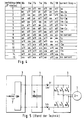
Figur 4 zeigt tabellarisch die möglichen Schaltzustände des 6-pulsigen Umrichters
5 zur Speisung eines dreiphasigen Motors 1 mit aktiver Steuerung 13 der Stromaufnahme
aus dem Netz 2 nach der Schaltungsanordnung von Figur 2. Unter Vernachlässigung
von Schalttotzeiten ergeben sich für die insgesamt vier Schaltmittel
6-8 und 18 insgesamt 24 = 16 verschiedene Schaltzustände, die in der Tabelle von
Figur 4 mit den Schaltzuständen 0 bis 15 gekennzeichnet sind.FIG. 4 shows in table form the possible switching states of the 6-
Wie beispielsweise in der bereits eingangs genannten Veröffentlichung von T.C.
Green und B.W. Williams näher erläutert, können die Schaltzustände der Schaltmittel
6-8, 18 mittels einer einfachen logischen Schaltung aus den sieben Steuersignalen
U+, U-, V+, V-, W+, W- und PFC der PWM-Einheit 19 identifiziert werden.
Aus der Symmetrie der Umrichterschaltung 5 ergibt sich, daß der Kondensatorstrom
Icap zum Beispiel in den Schaltzuständen 10 und 13 nur vom Phasenstrom
Iv bzw. in den Schaltzuständen 2 und 5 nur vom Phasenstrom Iv und dem
Netzstrom Im abhängt. Der A/D-Wandler 16 erfaßt synchron zu den momentanen
Schaltzuständen der Schaltmittel 6-8, 18 das Strommeßsignal Icap. Indem der
Kondensatorstrom Icap und gleichzeitig die Schaltzustände der Schaltmittel im
Augenblick der Strommessung erfaßt werden, kann der Verlauf der Phasenströme
Iu, Iv, Iw des Motors 1 und des Netzstromes Im rekonstruiert werden.As for example in the publication by T.C.
Green and B.W. Williams explained in more detail, the switching states of the switching means
6-8, 18 using a simple logic circuit from the seven control signals
U +, U-, V +, V-, W +, W- and PFC of the
Bei den Schaltzuständen 9 bis 14, d.h. bei geschlossenem Schalter 18 des Hochsetzstellers
13, fließt jeweils der Strom Iu, Iv, Iw einer Motorphase durch den Zwischenkreiskondensator
10. Beim Kurzschließen der Motorklemmen, d.h. bei Offensteuerung
(off) aller oberen Schaltmittel 6a-8a (Schaltzustand 15) oder bei Offensteuerung
aller unteren Schaltmittel 6b-8b (Schaltzustand 8), fließt kein Kondensatorstrom
Icap. Wird bei kurzgeschlossenen Motorklemmen das Schaltmittel
18 des Hochsetzstellers 13 geöffnet, so fließt über den Zwischenkreiskondensator
10 der Netzstrom Im. Bei den Schaltzuständen 1 bis 6, d.h. bei geöffnetem Schalter
18, fließt sowohl der Netzstrom Im als auch der Motorstrom Iu, Iv, Iw einer Motorphase
über den Zwischenkreiskondensator 10.With switching
Im Falle einer Schaltungsanordnung ohne Leistungsfaktorkorrektur mittels Hochsetzsteller
13 reduzieren sich die Schaltzustände der Tabelle von Figur 4 auf die
Schaltzustände 0 bis 7. Die Messung des momentanen Phasenstromes Iu, Iv, Iw
erfolgt dann durch eine Differenzmessung zwischen dem Summenstrom Netzstrom
Im + Phasenstrom Iu, Iv, Iw (Schaltzustände 1 bis 6) und dem Netzstrom Im
(Schaltzustände 0 und 7).In the case of a circuit arrangement without power factor correction using a step-up
Claims (9)
dadurch gekennzeichnet,
daß in unmittelbarer Serie mit einem Kondensator (10) des Spannungszwischenkreises (4) ein Mittel zu Strommessung (21) geschalten wird, über das genau und ausschließlich der Kondensatorstrom (Icap) fließt.Circuit arrangement for current measurement in a converter (5) fed from a voltage intermediate circuit (4),
characterized,
that in a direct series with a capacitor (10) of the voltage intermediate circuit (4) a means for current measurement (21) is switched, through which the capacitor current (Icap) flows precisely and exclusively.
dadurch gekennzeichnet,
daß in unmittelbarer Serie mit einem Kondensator (10) des Spannungszwischenkreises (4) ein Mittel zur Einschaltstrombegrenzung (21) bei Zuschaltung des Zwischenkreises mit entladenem Kondensator an das Netz (2) geschalten wird, über das genau und ausschließlich der Kondensatorstrom (Icap) fließt.Circuit arrangement for current limitation in a converter (5) fed from a voltage intermediate circuit (4),
characterized,
that in direct series with a capacitor (10) of the voltage intermediate circuit (4) means for inrush current limitation (21) is switched to the network (2) when the intermediate circuit is connected with a discharged capacitor, through which the capacitor current (Icap) flows precisely and exclusively.
dadurch gekennzeichnet,
daß das Mittel zur Strommessung (21) aus einem elektrischen ohmschen Festwiderstand besteht, in dem der Spannungsabfall an demselben das Meßsignal für den Kondensatorstrom (Icap) liefert.Circuit claim according to claim 1,
characterized,
that the means for current measurement (21) consists of an electrical ohmic fixed resistor in which the voltage drop across the same provides the measurement signal for the capacitor current (Icap).
dadurch gekennzeichnet,
daß zur Strommessung durch die den Umrichter (5) steuernde, elektrische Steuerung (17) der Kondensatorstrom (Icap) im Spannungszwischenkreis gemessen wird, und durch Zuordnung des momentanen Strom-Meßwertes zum momentanen Schaltzustand der Leistungsschalter (6...8) des Umrichters (5) bzw. eines Schalters zur Steuerung der Stromaufnahme (18) aus dem Netz (2) der Verlauf der Phasenströme in mindestens einer der Motorphasen (U,V,...) eines ein- oder mehrphasigen Motors (1) bzw. der Verlauf der Stromaufnahme (Im) aus dem Netz rekonstruiert wird.Circuit arrangement according to claim 1,
characterized,
that the capacitor current (Icap) in the voltage intermediate circuit is measured for current measurement by the electrical control (17) controlling the converter (5), and by assigning the current measured current value to the current switching state of the circuit breakers (6 ... 8) of the converter ( 5) or a switch for controlling the current consumption (18) from the network (2) the course of the phase currents in at least one of the motor phases (U, V, ...) of a single or multi-phase motor (1) or the course the current consumption (Im) is reconstructed from the network.
dadurch gekennzeichnet,
daß der Spannungsabfall über dem Meßwiderstand in Reihe mit dem Zwischenkreiskondensator unmittelbar ohne analoge Vorverstärkung (15) durch die aus einem Microcontroller oder DPS bestehende Steuervorrichtung (17) gemessen wird.Circuit arrangement according to claim 3,
characterized,
that the voltage drop across the measuring resistor in series with the intermediate circuit capacitor is measured directly without analog preamplification (15) by the control device (17) consisting of a microcontroller or DPS.
dadurch gekennzeichnet,
daß eine Treibervorrichtung zur Ansteuerung der Schaltmittel (6-8,18) vorgesehen ist, und daß das Meßsignal des Stromes (Icap) des Zwischenkreiskondensators (10) direkt der Treibervorrichtung (20) zugeführt wird, um bei Überschreiten eines bestimmten Grenzwertes des Strommeßsignales die Treibervorrichtung (20) in einen vorbestimmten Grundzustand zurückgesetzt wird (→ stop).Circuit arrangement according to claim 1,
characterized,
that a driver device for controlling the switching means (6-8, 18) is provided, and that the measurement signal of the current (Icap) of the intermediate circuit capacitor (10) is fed directly to the driver device (20) in order to drive the driver device when a certain limit value of the current measurement signal is exceeded (20) is reset to a predetermined basic state (→ stop).
dadurch gekennzeichnet,
daß das Mittel zur Einschaltstrombegrenzung (21) aus einem ohmschen Festwiderstand besteht.Circuit arrangement according to claim 2,
characterized,
that the means for inrush current limitation (21) consists of an ohmic fixed resistor.
dadurch gekennzeichnet,
daß das Mittel zur Einschaltstrombegrenzung (21) aus einem temperaturabhängigen Widerstand (NTC) besteht. Circuit arrangement according to claim 2,
characterized,
that the means for inrush current limitation (21) consists of a temperature-dependent resistor (NTC).
dadurch gekennzeichnet,
daß der Widerstand (21) in Reihe zum Kondensator (10) des Spannungszwischenkreises (4) aus einer Reihenschaltung aus Festwiderstand zur Strommessung sowie einem temperaturabhängigen Widerstand (NTC) zur zusätzlichen Einschaltstrombegrenzung besteht.Circuit arrangement according to claim 1 or 2,
characterized,
that the resistor (21) in series with the capacitor (10) of the voltage intermediate circuit (4) consists of a series circuit of fixed resistor for current measurement and a temperature-dependent resistor (NTC) for additional inrush current limitation.
Applications Claiming Priority (2)
| Application Number | Priority Date | Filing Date | Title |
|---|---|---|---|
| DE19834315 | 1998-07-30 | ||
| DE19834315A DE19834315A1 (en) | 1998-07-30 | 1998-07-30 | Circuit arrangement for measuring and limiting currents in converters for feeding motors |
Publications (3)
| Publication Number | Publication Date |
|---|---|
| EP0977337A2 true EP0977337A2 (en) | 2000-02-02 |
| EP0977337A3 EP0977337A3 (en) | 2005-06-01 |
| EP0977337B1 EP0977337B1 (en) | 2011-03-09 |
Family
ID=7875815
Family Applications (1)
| Application Number | Title | Priority Date | Filing Date |
|---|---|---|---|
| EP99113966A Expired - Lifetime EP0977337B1 (en) | 1998-07-30 | 1999-07-17 | Circuit for measuring and limiting currents in converters for supplying motors |
Country Status (3)
| Country | Link |
|---|---|
| EP (1) | EP0977337B1 (en) |
| AT (1) | ATE501540T1 (en) |
| DE (2) | DE19834315A1 (en) |
Cited By (9)
| Publication number | Priority date | Publication date | Assignee | Title |
|---|---|---|---|---|
| EP1225452A2 (en) * | 2001-01-19 | 2002-07-24 | Robert Bosch Gmbh | Current measuring procedure for half-bridges |
| WO2003038987A1 (en) * | 2001-11-02 | 2003-05-08 | Leopold Kostal Gmbh & Co. Kg | Method for operating a control device |
| EP1333570A2 (en) * | 2002-01-31 | 2003-08-06 | Diehl AKO Stiftung & Co. KG | Method and circuit arrangement for current measuring and limitation |
| WO2008034515A1 (en) * | 2006-09-22 | 2008-03-27 | Recaro Aircraft Seating Gmbh & Co. Kg | Power supply device with power factor correction and (startup) current limitation |
| US7804288B2 (en) | 2006-12-21 | 2010-09-28 | Vacon Oyj | Current measuring arrangement of a frequency converter |
| WO2012163645A3 (en) * | 2011-05-30 | 2013-10-03 | Robert Bosch Gmbh | Method for determining current in a polyphase machine |
| CN109546911A (en) * | 2018-11-29 | 2019-03-29 | 宁波诺丁汉大学 | Based on the single current sensor motor control method for mixing pulse modulation technology |
| WO2019091996A1 (en) * | 2017-11-08 | 2019-05-16 | Ebm-Papst Mulfingen Gmbh & Co. Kg | Capacitance reduction |
| CN114830269A (en) * | 2019-11-05 | 2022-07-29 | 西门子股份公司 | Device for voltage equalization in the case of a square-wave voltage of an electric motor |
Families Citing this family (2)
| Publication number | Priority date | Publication date | Assignee | Title |
|---|---|---|---|---|
| DE102010015312A1 (en) * | 2010-04-17 | 2011-10-20 | Audi Ag | High-voltage system for a motor vehicle and method for diagnosing a high-voltage system for a motor vehicle |
| DE102011003897A1 (en) * | 2011-02-10 | 2012-08-16 | Robert Bosch Gmbh | Method and device for current measurement |
Family Cites Families (5)
| Publication number | Priority date | Publication date | Assignee | Title |
|---|---|---|---|---|
| SE467130B (en) * | 1990-09-14 | 1992-05-25 | Electrolux Ab | POWER SUPPLY FOR GENERATION OF A PRINCIPLY SINUS SHAPED RISK |
| JPH05103494A (en) * | 1991-10-03 | 1993-04-23 | Toshiba Corp | Inverter device |
| US5373195A (en) * | 1992-12-23 | 1994-12-13 | General Electric Company | Technique for decoupling the energy storage system voltage from the DC link voltage in AC electric drive systems |
| DK172570B1 (en) * | 1995-01-23 | 1999-01-25 | Danfoss As | Inverters and method for measuring the inverter phase currents |
| JPH10150775A (en) * | 1996-11-18 | 1998-06-02 | Toshiba Corp | Power converter equipment |
-
1998
- 1998-07-30 DE DE19834315A patent/DE19834315A1/en not_active Withdrawn
-
1999
- 1999-07-17 AT AT99113966T patent/ATE501540T1/en active
- 1999-07-17 DE DE59915255T patent/DE59915255D1/en not_active Expired - Lifetime
- 1999-07-17 EP EP99113966A patent/EP0977337B1/en not_active Expired - Lifetime
Non-Patent Citations (1)
| Title |
|---|
| None |
Cited By (15)
| Publication number | Priority date | Publication date | Assignee | Title |
|---|---|---|---|---|
| EP1225452A2 (en) * | 2001-01-19 | 2002-07-24 | Robert Bosch Gmbh | Current measuring procedure for half-bridges |
| EP1225452A3 (en) * | 2001-01-19 | 2004-01-28 | Robert Bosch Gmbh | Current measuring procedure for half-bridges |
| WO2003038987A1 (en) * | 2001-11-02 | 2003-05-08 | Leopold Kostal Gmbh & Co. Kg | Method for operating a control device |
| EP1333570A2 (en) * | 2002-01-31 | 2003-08-06 | Diehl AKO Stiftung & Co. KG | Method and circuit arrangement for current measuring and limitation |
| EP1333570A3 (en) * | 2002-01-31 | 2004-09-08 | Diehl AKO Stiftung & Co. KG | Method and circuit arrangement for current measuring and limitation |
| WO2008034515A1 (en) * | 2006-09-22 | 2008-03-27 | Recaro Aircraft Seating Gmbh & Co. Kg | Power supply device with power factor correction and (startup) current limitation |
| US7804288B2 (en) | 2006-12-21 | 2010-09-28 | Vacon Oyj | Current measuring arrangement of a frequency converter |
| EP1936794A3 (en) * | 2006-12-21 | 2016-09-07 | Vacon Oy | Current measuring arrangement of a frequency converter |
| WO2012163645A3 (en) * | 2011-05-30 | 2013-10-03 | Robert Bosch Gmbh | Method for determining current in a polyphase machine |
| US9285400B2 (en) | 2011-05-30 | 2016-03-15 | Robert Bosch Gmbh | Method for determining current in a polyphase machine |
| WO2019091996A1 (en) * | 2017-11-08 | 2019-05-16 | Ebm-Papst Mulfingen Gmbh & Co. Kg | Capacitance reduction |
| US11362603B2 (en) | 2017-11-08 | 2022-06-14 | Ebm-Papst Mulfingen Gmbh & Co. Kg | Capacitance reductions |
| CN109546911A (en) * | 2018-11-29 | 2019-03-29 | 宁波诺丁汉大学 | Based on the single current sensor motor control method for mixing pulse modulation technology |
| CN109546911B (en) * | 2018-11-29 | 2021-06-08 | 宁波诺丁汉大学 | Single current sensor motor control method based on mixed pulse width modulation technology |
| CN114830269A (en) * | 2019-11-05 | 2022-07-29 | 西门子股份公司 | Device for voltage equalization in the case of a square-wave voltage of an electric motor |
Also Published As
| Publication number | Publication date |
|---|---|
| EP0977337B1 (en) | 2011-03-09 |
| EP0977337A3 (en) | 2005-06-01 |
| DE59915255D1 (en) | 2011-04-21 |
| DE19834315A1 (en) | 2000-02-03 |
| ATE501540T1 (en) | 2011-03-15 |
Similar Documents
| Publication | Publication Date | Title |
|---|---|---|
| EP1369985B1 (en) | Inverter for transforming a DC voltage into an AC current or an AC voltage | |
| EP2290797B1 (en) | Method of converting a DC voltage of a DC source, in particular of a photovoltaic DC source, in an AC voltage | |
| DE2225609C2 (en) | Arrangement for controlling the speed of a multiphase alternating current asynchronous motor fed via a static converter with variable voltage and, for example, with proportional frequency | |
| WO2010003941A2 (en) | Network connection of solar cells | |
| DE10356515A1 (en) | drive system | |
| EP3211784A1 (en) | Double submodule for a modular multilevel converter and modular multilevel converter comprising same | |
| DE102012101156A1 (en) | Network feed device, energy supply system and method for operating a network feed device | |
| EP0865150A2 (en) | Circuit for continuous direct or indirect variation of DC and/or AC current flowing in a load supplied by DC or AC source voltage or any combination of these voltages | |
| EP2608344A1 (en) | Method for protecting an intermediate circuit condenser in a frequency converter circuit | |
| EP2863528A1 (en) | Operation of an inverter as a DC/DC-converter | |
| EP0977337B1 (en) | Circuit for measuring and limiting currents in converters for supplying motors | |
| DE102018207290A1 (en) | Configurable charging device and method for configuring the charging device | |
| EP3625884A1 (en) | Galvanically coupled electrical converter | |
| EP1508962B1 (en) | Converter with intermediate voltage link | |
| EP2807738A2 (en) | Multicell converter | |
| WO2014127871A2 (en) | Internal energy supply of energy storage modules for an energy storage device, and energy storage device with such an internal energy supply | |
| DE102018221519B4 (en) | Vehicle-side loading device | |
| DE102007058681A1 (en) | Step up and step down controller, particularly for feeding, for use with half bridge and full bridge for converting direct current voltage into output direct current voltage, has fuel cells in electrical network | |
| DE102006016501A1 (en) | Power semiconductor module e.g. insulated gate bipolar transistor six pack, for use in condenser less voltage link frequency converter, has one connection pin connected with negative direct current cable using additional cable | |
| DE112019006992T5 (en) | DC power supply device, power conversion device, and refrigeration cycle device | |
| DE102009008072A1 (en) | Step-up converter for use in three-phase power inverter to step up input direct current voltage into high output direct current voltage, has high and low side switching transistors controlled by control unit in synchronized manner | |
| DE3724526A1 (en) | RECTIFIER CIRCUIT FOR SUPPLYING A DC INTERMEDIATE CIRCUIT | |
| WO2013092037A2 (en) | Rectifier circuit | |
| WO2013092039A1 (en) | Power converter circuit | |
| EP2784931A1 (en) | Method and control circuit for controlling a brushless electric motor |
Legal Events
| Date | Code | Title | Description |
|---|---|---|---|
| PUAI | Public reference made under article 153(3) epc to a published international application that has entered the european phase |
Free format text: ORIGINAL CODE: 0009012 |
|
| AK | Designated contracting states |
Kind code of ref document: A2 Designated state(s): AT BE CH CY DE DK ES FI FR GB GR IE IT LI LU MC NL PT SE |
|
| AX | Request for extension of the european patent |
Free format text: AL;LT;LV;MK;RO;SI |
|
| RAP1 | Party data changed (applicant data changed or rights of an application transferred) |
Owner name: DIEHL AKO STIFTUNG & CO. KG |
|
| PUAL | Search report despatched |
Free format text: ORIGINAL CODE: 0009013 |
|
| AK | Designated contracting states |
Kind code of ref document: A3 Designated state(s): AT BE CH CY DE DK ES FI FR GB GR IE IT LI LU MC NL PT SE |
|
| AX | Request for extension of the european patent |
Extension state: AL LT LV MK RO SI |
|
| RIC1 | Information provided on ipc code assigned before grant |
Ipc: 7G 01R 19/25 B Ipc: 7H 02H 7/12 A |
|
| 17P | Request for examination filed |
Effective date: 20050604 |
|
| AKX | Designation fees paid |
Designated state(s): AT BE CH CY DE DK ES FI FR GB GR IE IT LI LU MC NL PT SE |
|
| 17Q | First examination report despatched |
Effective date: 20051104 |
|
| GRAP | Despatch of communication of intention to grant a patent |
Free format text: ORIGINAL CODE: EPIDOSNIGR1 |
|
| GRAS | Grant fee paid |
Free format text: ORIGINAL CODE: EPIDOSNIGR3 |
|
| GRAA | (expected) grant |
Free format text: ORIGINAL CODE: 0009210 |
|
| AK | Designated contracting states |
Kind code of ref document: B1 Designated state(s): AT BE CH CY DE DK ES FI FR GB GR IE IT LI LU MC NL PT SE |
|
| REG | Reference to a national code |
Ref country code: GB Ref legal event code: FG4D Free format text: NOT ENGLISH |
|
| REG | Reference to a national code |
Ref country code: CH Ref legal event code: EP |
|
| REG | Reference to a national code |
Ref country code: IE Ref legal event code: FG4D Free format text: LANGUAGE OF EP DOCUMENT: GERMAN |
|
| REF | Corresponds to: |
Ref document number: 59915255 Country of ref document: DE Date of ref document: 20110421 Kind code of ref document: P |
|
| REG | Reference to a national code |
Ref country code: DE Ref legal event code: R096 Ref document number: 59915255 Country of ref document: DE Effective date: 20110421 |
|
| REG | Reference to a national code |
Ref country code: NL Ref legal event code: VDEP Effective date: 20110309 |
|
| PG25 | Lapsed in a contracting state [announced via postgrant information from national office to epo] |
Ref country code: ES Free format text: LAPSE BECAUSE OF FAILURE TO SUBMIT A TRANSLATION OF THE DESCRIPTION OR TO PAY THE FEE WITHIN THE PRESCRIBED TIME-LIMIT Effective date: 20110620 Ref country code: GR Free format text: LAPSE BECAUSE OF FAILURE TO SUBMIT A TRANSLATION OF THE DESCRIPTION OR TO PAY THE FEE WITHIN THE PRESCRIBED TIME-LIMIT Effective date: 20110610 Ref country code: SE Free format text: LAPSE BECAUSE OF FAILURE TO SUBMIT A TRANSLATION OF THE DESCRIPTION OR TO PAY THE FEE WITHIN THE PRESCRIBED TIME-LIMIT Effective date: 20110309 |
|
| PG25 | Lapsed in a contracting state [announced via postgrant information from national office to epo] |
Ref country code: NL Free format text: LAPSE BECAUSE OF FAILURE TO SUBMIT A TRANSLATION OF THE DESCRIPTION OR TO PAY THE FEE WITHIN THE PRESCRIBED TIME-LIMIT Effective date: 20110309 Ref country code: CY Free format text: LAPSE BECAUSE OF FAILURE TO SUBMIT A TRANSLATION OF THE DESCRIPTION OR TO PAY THE FEE WITHIN THE PRESCRIBED TIME-LIMIT Effective date: 20110309 Ref country code: FI Free format text: LAPSE BECAUSE OF FAILURE TO SUBMIT A TRANSLATION OF THE DESCRIPTION OR TO PAY THE FEE WITHIN THE PRESCRIBED TIME-LIMIT Effective date: 20110309 |
|
| REG | Reference to a national code |
Ref country code: IE Ref legal event code: FD4D |
|
| PG25 | Lapsed in a contracting state [announced via postgrant information from national office to epo] |
Ref country code: PT Free format text: LAPSE BECAUSE OF FAILURE TO SUBMIT A TRANSLATION OF THE DESCRIPTION OR TO PAY THE FEE WITHIN THE PRESCRIBED TIME-LIMIT Effective date: 20110711 Ref country code: IE Free format text: LAPSE BECAUSE OF FAILURE TO SUBMIT A TRANSLATION OF THE DESCRIPTION OR TO PAY THE FEE WITHIN THE PRESCRIBED TIME-LIMIT Effective date: 20110309 |
|
| PLBE | No opposition filed within time limit |
Free format text: ORIGINAL CODE: 0009261 |
|
| STAA | Information on the status of an ep patent application or granted ep patent |
Free format text: STATUS: NO OPPOSITION FILED WITHIN TIME LIMIT |
|
| BERE | Be: lapsed |
Owner name: DIEHL AKO STIFTUNG & CO. K.G. Effective date: 20110731 |
|
| 26N | No opposition filed |
Effective date: 20111212 |
|
| PG25 | Lapsed in a contracting state [announced via postgrant information from national office to epo] |
Ref country code: DK Free format text: LAPSE BECAUSE OF FAILURE TO SUBMIT A TRANSLATION OF THE DESCRIPTION OR TO PAY THE FEE WITHIN THE PRESCRIBED TIME-LIMIT Effective date: 20110309 Ref country code: MC Free format text: LAPSE BECAUSE OF NON-PAYMENT OF DUE FEES Effective date: 20110731 |
|
| REG | Reference to a national code |
Ref country code: CH Ref legal event code: PL |
|
| GBPC | Gb: european patent ceased through non-payment of renewal fee |
Effective date: 20110717 |
|
| REG | Reference to a national code |
Ref country code: DE Ref legal event code: R097 Ref document number: 59915255 Country of ref document: DE Effective date: 20111212 |
|
| PG25 | Lapsed in a contracting state [announced via postgrant information from national office to epo] |
Ref country code: BE Free format text: LAPSE BECAUSE OF NON-PAYMENT OF DUE FEES Effective date: 20110731 Ref country code: CH Free format text: LAPSE BECAUSE OF NON-PAYMENT OF DUE FEES Effective date: 20110731 Ref country code: LI Free format text: LAPSE BECAUSE OF NON-PAYMENT OF DUE FEES Effective date: 20110731 |
|
| PG25 | Lapsed in a contracting state [announced via postgrant information from national office to epo] |
Ref country code: IT Free format text: LAPSE BECAUSE OF FAILURE TO SUBMIT A TRANSLATION OF THE DESCRIPTION OR TO PAY THE FEE WITHIN THE PRESCRIBED TIME-LIMIT Effective date: 20110309 |
|
| PG25 | Lapsed in a contracting state [announced via postgrant information from national office to epo] |
Ref country code: GB Free format text: LAPSE BECAUSE OF NON-PAYMENT OF DUE FEES Effective date: 20110717 |
|
| REG | Reference to a national code |
Ref country code: AT Ref legal event code: MM01 Ref document number: 501540 Country of ref document: AT Kind code of ref document: T Effective date: 20110717 |
|
| PG25 | Lapsed in a contracting state [announced via postgrant information from national office to epo] |
Ref country code: AT Free format text: LAPSE BECAUSE OF NON-PAYMENT OF DUE FEES Effective date: 20110717 |
|
| PG25 | Lapsed in a contracting state [announced via postgrant information from national office to epo] |
Ref country code: LU Free format text: LAPSE BECAUSE OF NON-PAYMENT OF DUE FEES Effective date: 20110717 |
|
| REG | Reference to a national code |
Ref country code: FR Ref legal event code: PLFP Year of fee payment: 17 |
|
| PGFP | Annual fee paid to national office [announced via postgrant information from national office to epo] |
Ref country code: FR Payment date: 20150626 Year of fee payment: 17 |
|
| PGFP | Annual fee paid to national office [announced via postgrant information from national office to epo] |
Ref country code: DE Payment date: 20150923 Year of fee payment: 17 |
|
| REG | Reference to a national code |
Ref country code: DE Ref legal event code: R119 Ref document number: 59915255 Country of ref document: DE |
|
| PG25 | Lapsed in a contracting state [announced via postgrant information from national office to epo] |
Ref country code: DE Free format text: LAPSE BECAUSE OF NON-PAYMENT OF DUE FEES Effective date: 20170201 Ref country code: FR Free format text: LAPSE BECAUSE OF NON-PAYMENT OF DUE FEES Effective date: 20160801 |
|
| REG | Reference to a national code |
Ref country code: FR Ref legal event code: ST Effective date: 20170331 |