EP0976928B1 - Schaufelanordnung für eine Strömungsmaschine - Google Patents
Schaufelanordnung für eine Strömungsmaschine Download PDFInfo
- Publication number
- EP0976928B1 EP0976928B1 EP99114975A EP99114975A EP0976928B1 EP 0976928 B1 EP0976928 B1 EP 0976928B1 EP 99114975 A EP99114975 A EP 99114975A EP 99114975 A EP99114975 A EP 99114975A EP 0976928 B1 EP0976928 B1 EP 0976928B1
- Authority
- EP
- European Patent Office
- Prior art keywords
- blade
- wall
- flow
- arrangement according
- auxiliary vane
- Prior art date
- Legal status (The legal status is an assumption and is not a legal conclusion. Google has not performed a legal analysis and makes no representation as to the accuracy of the status listed.)
- Expired - Lifetime
Links
Images


Classifications
-
- F—MECHANICAL ENGINEERING; LIGHTING; HEATING; WEAPONS; BLASTING
- F04—POSITIVE - DISPLACEMENT MACHINES FOR LIQUIDS; PUMPS FOR LIQUIDS OR ELASTIC FLUIDS
- F04D—NON-POSITIVE-DISPLACEMENT PUMPS
- F04D29/00—Details, component parts, or accessories
- F04D29/26—Rotors specially for elastic fluids
- F04D29/32—Rotors specially for elastic fluids for axial flow pumps
- F04D29/321—Rotors specially for elastic fluids for axial flow pumps for axial flow compressors
- F04D29/324—Blades
-
- F—MECHANICAL ENGINEERING; LIGHTING; HEATING; WEAPONS; BLASTING
- F01—MACHINES OR ENGINES IN GENERAL; ENGINE PLANTS IN GENERAL; STEAM ENGINES
- F01D—NON-POSITIVE DISPLACEMENT MACHINES OR ENGINES, e.g. STEAM TURBINES
- F01D5/00—Blades; Blade-carrying members; Heating, heat-insulating, cooling or antivibration means on the blades or the members
- F01D5/12—Blades
- F01D5/14—Form or construction
- F01D5/141—Shape, i.e. outer, aerodynamic form
- F01D5/145—Means for influencing boundary layers or secondary circulations
-
- F—MECHANICAL ENGINEERING; LIGHTING; HEATING; WEAPONS; BLASTING
- F04—POSITIVE - DISPLACEMENT MACHINES FOR LIQUIDS; PUMPS FOR LIQUIDS OR ELASTIC FLUIDS
- F04D—NON-POSITIVE-DISPLACEMENT PUMPS
- F04D29/00—Details, component parts, or accessories
- F04D29/18—Rotors
- F04D29/181—Axial flow rotors
-
- F—MECHANICAL ENGINEERING; LIGHTING; HEATING; WEAPONS; BLASTING
- F04—POSITIVE - DISPLACEMENT MACHINES FOR LIQUIDS; PUMPS FOR LIQUIDS OR ELASTIC FLUIDS
- F04D—NON-POSITIVE-DISPLACEMENT PUMPS
- F04D29/00—Details, component parts, or accessories
- F04D29/26—Rotors specially for elastic fluids
- F04D29/28—Rotors specially for elastic fluids for centrifugal or helico-centrifugal pumps for radial-flow or helico-centrifugal pumps
- F04D29/30—Vanes
-
- F—MECHANICAL ENGINEERING; LIGHTING; HEATING; WEAPONS; BLASTING
- F04—POSITIVE - DISPLACEMENT MACHINES FOR LIQUIDS; PUMPS FOR LIQUIDS OR ELASTIC FLUIDS
- F04D—NON-POSITIVE-DISPLACEMENT PUMPS
- F04D29/00—Details, component parts, or accessories
- F04D29/40—Casings; Connections of working fluid
- F04D29/52—Casings; Connections of working fluid for axial pumps
- F04D29/54—Fluid-guiding means, e.g. diffusers
- F04D29/541—Specially adapted for elastic fluid pumps
- F04D29/542—Bladed diffusers
- F04D29/544—Blade shapes
-
- F—MECHANICAL ENGINEERING; LIGHTING; HEATING; WEAPONS; BLASTING
- F04—POSITIVE - DISPLACEMENT MACHINES FOR LIQUIDS; PUMPS FOR LIQUIDS OR ELASTIC FLUIDS
- F04D—NON-POSITIVE-DISPLACEMENT PUMPS
- F04D29/00—Details, component parts, or accessories
- F04D29/66—Combating cavitation, whirls, noise, vibration or the like; Balancing
- F04D29/68—Combating cavitation, whirls, noise, vibration or the like; Balancing by influencing boundary layers
- F04D29/681—Combating cavitation, whirls, noise, vibration or the like; Balancing by influencing boundary layers especially adapted for elastic fluid pumps
-
- Y—GENERAL TAGGING OF NEW TECHNOLOGICAL DEVELOPMENTS; GENERAL TAGGING OF CROSS-SECTIONAL TECHNOLOGIES SPANNING OVER SEVERAL SECTIONS OF THE IPC; TECHNICAL SUBJECTS COVERED BY FORMER USPC CROSS-REFERENCE ART COLLECTIONS [XRACs] AND DIGESTS
- Y02—TECHNOLOGIES OR APPLICATIONS FOR MITIGATION OR ADAPTATION AGAINST CLIMATE CHANGE
- Y02T—CLIMATE CHANGE MITIGATION TECHNOLOGIES RELATED TO TRANSPORTATION
- Y02T50/00—Aeronautics or air transport
- Y02T50/60—Efficient propulsion technologies, e.g. for aircraft
Definitions
- the invention relates to a blade arrangement for a turbomachine, for example a compressor, a pump or a turbine, with a blade and at least a wall, the blade extending from the wall into a flow and in the operation of the turbomachine in the transition area between the wall and Blade forms a corner flow.
- a turbomachine for example a compressor, a pump or a turbine
- Such blade arrangements are found in both types of turbomachines for liquid as well as gaseous flow media.
- the blades In axial flow machines, the blades extend radially from one hub Outward direction in the current.
- the hub sections between successive In terms of flow technology, blades represent a wall, with themselves in the transition area forms a corner flow between the wall and the blade.
- the Buckets can either be part of a rotating impeller or a stationary one Be the guide wheel.
- the blade is between the hub and one attached ring-shaped housing that stands still relative to the hub. In this case forms both a hub-side and a housing-side corner flow.
- a very complex corner flow arises between the blade and the housing when Rotate housing and blade relative to each other and through a small gap from each other are separated.
- radial flow machines such as radial fans
- the Blades are on the axial end face of one or more annular flanges assembled.
- a corner flow forms in the transition area between Shovel and wall out.
- turbomachines The technology of these turbomachines is generally very mature, which leads to high efficiency.
- axial compressors achieve efficiencies between 85% and 92%, with turbines these values are even higher.
- auxiliary wings can increase the efficiency in a cascade of a turbomachine.
- these auxiliary wings are intended to reduce a large-scale secondary flow or eliminate that in a cascade due to the delayed currents near the wall and the pressure distribution within the cascade.
- the prior art internals known by the fluid of a corner flow in Transition area between the wall and blade is fed so that it accelerates becomes.
- the auxiliary wings can be on the blade surface or on the surface of the Wall.
- a generic blade arrangement in which the auxiliary wing is arranged on the surface of the blade, is known from US 2,920,864. These auxiliary wings each produce a tip vortex, the direction of rotation of which is the direction of rotation the secondary flow is opposite. This longitudinal vortex is said to be the vortex of the Weaken or extinguish secondary flow.
- auxiliary wings When blading US 3,193,185, the surfaces of the blades are also provided with auxiliary wings. These auxiliary wings are said to be more thoroughly mixed Cause boundary layer, which delays their detachment. These auxiliary wings work as guide vanes, through the wall flow from faster flowing areas in more slowly flowing areas. The disadvantage of this arrangement lies in one disproportionately high flow resistance of these guide vanes.
- Blade arrangements in which the auxiliary wing is arranged on the wall are also known from the prior art.
- a generic arrangement is for example known from US 3,193,185.
- the disadvantage of this Auxiliary wing also lies in its high flow resistance.
- a turbine wheel which has both a semi-axial fluid supply and also has a radial fluid supply line.
- Avoiding flow separation are auxiliary blades between the turbine blades arranged, the blade depth about 50% of the blade depth of the main blades is. These auxiliary blades also have the disadvantage that their flow resistance is too large for practical use in energy-efficient turbines.
- the invention is therefore the Task based on the blades of turbo machines by simple structural Changes to the blade arrangement to improve the efficiency of turbomachines increases.
- This object is inventively for a blade arrangement of the aforementioned Type in which auxiliary blades are arranged on the blade surface, solved by that the surface of the blade and / or the wall in the area of the corner flow with at least one small compared to the shovel, sticking out from the surface the blade and / or the wall away in the flow extending auxiliary wing is, which is against the current prevailing at this point, where in the operation of the turbomachine in the wake of the auxiliary wing forms a vortex, the Direction of rotation is directed so that on the blade surface assigned to the auxiliary wing a speed from the center of the bucket to the transition area from Wall and shovel is induced.
- this object is achieved in that the auxiliary wing as a vortex generator small compared to the blade and formed in the area of Corner flow is arranged.
- the principle of action on which the auxiliary wing is based is based on avoidance or Reduction of corner flow separation.
- the corner flow is due to the Proximity to the two surfaces of the wall and the shovel very slowly and consequently loosens already in operation of the turbomachine. This detachment of the corner flow is subject to losses and also generates vibrations and flow noise.
- auxiliary wing sometimes also as a vortex generator in flow technology referred to, attached to the surface of the blade and / or the wall becomes.
- This auxiliary wing creates a single strong longitudinal vortex in its wake, that is, a vortex whose axis is oriented essentially in the direction of flow is. Since the auxiliary wing is attached in the area of the corner flow, this influences Whirl the corner flow by making it flow rapidly due to a rotating movement Fluid of the external flow along the blade surface assigned to the auxiliary wing the slow corner current, accelerating it and preventing it from detaching.
- the auxiliary wing has the advantage over other methods that it does not supply any energy needed from the outside and is therefore functional at all times.
- the auxiliary wing is mechanical easy to manufacture and insensitive to impurities in the flow.
- auxiliary wing in the flow area near the wall, the so-called boundary layer, due to its employment against the ruling one Flow direction acts as a nozzle and channels the corner flow and thereby accelerated. At the same time, it acts as a fence that prevents slow-flowing Fluid the corner flow itself with the faster flow around the blade center can mix.
- auxiliary wing in the shovel-wall transition area no additional flow resistance as with an arrangement generated in the middle of the blade, although it has an additional flow obstacle in the Fluid machine represents. This effect could be proven in tests and can only be explained in such a way that the corner flow, which is no longer replacing gain in efficiency the losses generated by the auxiliary wing surpasses.
- the additional weight of the auxiliary wing is also due to the adjacent corner flow increased buoyancy of the blades and the associated Performance increase more than compensated.
- the auxiliary wing arranged on the wall has the advantage that when it is replaced the blades and, in the case of adjustable blades, always a correct relative position to the shovel.
- the lateral distance of the auxiliary wing from the housing wall should not be too great be otherwise the corner flow in the area of the blade-wall transition is not can be influenced more by the auxiliary wing.
- the exact size of the auxiliary wing the is necessary in order to optimally influence the corner flow, ie The person skilled in the art can achieve maximum efficiency gain without Determine further own considerations through experiments. First of all, it is recommended to start with an auxiliary wing, in which a detachment of the corner flow safely can be avoided. The auxiliary wing should then be gradually reduced until the desired effect begins to fail and the corner flow begins again replace. This is the limit caused by the auxiliary wing itself Loss or its flow resistance least.
- auxiliary wing If only the auxiliary wing is so large that the separation of the corner flow is just suppressed, they are Flow losses are lowest and efficiency gains are greatest.
- the dimensions of a vortex generator suitably dimensioned in this way then surprisingly small and are generally in the range of a few percent the bucket depth.
- the vortex through which the corner flow is mixed with the outside flow and thereby reducing or preventing the separation of the corner flow can be reinforced that in a further advantageous embodiment of the invention an upstream leading edge of the auxiliary wing at a different distance from a corner formed by the shovel and the wall is arranged as a downstream one Trailing edge of the auxiliary wing.
- the Trailing edge from the wall should be less than the leading edge, if the auxiliary wing is attached to the blade surface. If the auxiliary wing on the Wall is attached, then it is advantageous if the trailing edge is less of the Blade surface is spaced as the leading edge.
- a height of Auxiliary wing in a direction perpendicular to the surface of the blade advantageously at least a boundary layer thickness of the flow around the blade at the location of the auxiliary wing correspond.
- the height of the auxiliary wing can over the wall at least the boundary layer thickness of the wall flow at the Correspond to the position of the auxiliary wing.
- An auxiliary wing with these dimensions caused only slight flow losses and certainly influences the corner flow.
- the boundary layer thickness of the flow around the blade at the location of the auxiliary wing can be determined, for example, by measuring a speed profile at this point become. Such measurement methods are familiar to the person skilled in the art.
- the auxiliary wing may extend substantially perpendicularly from the surface of the blade extend the flow and thus act as a barrier between the corner flow and the flow around the blade act in the middle of the blade.
- a stronger nozzle effect towards the transition area between the shovel and the wall can be achieved if in a further advantageous embodiment the auxiliary wing from the surface of the blade in the direction of the wall or from the wall in Extends in the direction of the blade surface.
- the auxiliary wing can also be bridge-shaped extend from the blade surface to the wall.
- the corner flow is particularly at risk of detachment on the suction side of the blade. It is therefore useful in an advantageous development of the invention if the auxiliary wing is arranged on the suction side of the blade.
- the manufacturing costs of the blade according to the invention can be reduced if the Auxiliary wing essentially plate-shaped or in the form of a, preferably weak, curved plate is designed.
- the auxiliary wing made of sheet metal or can be easily made from plastic in these forms.
- the corner flow can be suppressed particularly effectively when the auxiliary wing has a wing profile similar to a wing. Generate such thickness profiles a strong vortex in its wake even at small angles of attack.
- the length of the auxiliary wing in an advantageous development of the Blade in the direction of the blade flow around at least one height of the auxiliary wing perpendicular to the surface of the blade and / or wall.
- the length of the auxiliary wing is double is as big as its height.
- the auxiliary wing with an angle of attack between 3 ° and 30 °, preferably between 5 ° and 15 °, against the flow around the blade at the location of the auxiliary wing. Because the flow directions in a turbomachine are constantly changing over the blade change, it always makes sense in this context to include the directions to connect a local flow direction at the location of the auxiliary wing.
- the auxiliary wing becomes ineffective when the flow has already been replaced at its position is.
- the outline of the auxiliary wing in the direction of view perpendicular to the direction of the blade flow essentially triangular or essentially at the location of the auxiliary wing be rectangular.
- the leading edge of the auxiliary wing can also be straight or curved his. Curved or inclined leading edges prevent contamination can stick to the leading edges.
- Triangular or delta winged Auxiliary wings create weaker horseshoe vertebrae at their leading edges and guide them thereby to lower flow losses.
- connection type of the auxiliary wing to the blade surface depends on the the flow conditions prevailing in the blade and those used for the blades Materials.
- the auxiliary wing can pass through on the blade surface a thermal joining process such as welding, in particular spot welding, or Brazing attached. This type of fastening gives particularly strong connections. If the auxiliary wing is screwed or riveted to the shovel, then the auxiliary wing can be easily removed and replaced for maintenance or repair purposes. Gluing the auxiliary wing to the shovel in turn represents a quick and cheap Fastening variant.
- the auxiliary wing can be made in one piece with the Blade manufactured and for example by forging and / or sintering and / or Milled and / or a gel-forming process such as electrical discharge machining his.
- This type of manufacture of the auxiliary wing enables the manufacture of Shovel and auxiliary wing in one step. No further processing stations are necessary which reduces manufacturing times and costs.
- the auxiliary wing can be covered with a protective cover to retrofit existing blades the bucket can be integrated, for vibration damping or as corrosion protection is pulled over the shovel.
- existing ones can be Flow machines can be easily and inexpensively retrofitted with an auxiliary wing.
- the invention is particularly well suited to use in turbomachines that function as an axial flow machine are trained.
- the suppression of detachment can be reliable can be avoided if the blade is part of an impeller or a stator is.
- the blades of the impeller or stator are in the generally attached to a hub, the wall being formed by the hub. Indeed In an advantageous further development, the blade can also be between a hub and a housing.
- the invention further relates to a kit for a turbomachine, consisting of a shovel and a shovel holder forming a wall, in which the Shovel is held.
- a kit for a turbomachine consisting of a shovel and a shovel holder forming a wall, in which the Shovel is held.
- an auxiliary wing is provided with which the Blade and / or the wall can be equipped according to one of the above embodiments is.
- This blade holder can be used, for example, in axial flow machines Hub or housing.
- the blade holder is used in radial flow machines usually an annular flange.
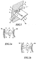
- FIG. 1 shows a first exemplary embodiment of the blade 1, which extends from a wall 2 extends into a flow 3.
- the wall 2 represents an annular housing
- Fig. 1 shows an oblique view of the suction side of the blade 1.
- the suction side is the side of the blade on the higher side due to the higher one Flow velocities opposite the other side of the blade 1 are a negative pressure is produced.
- an auxiliary wing 4 is attached, which extends from the surface of the Blade 1 extends into the flow 3.
- the auxiliary wing is slightly against the current 3 employed at the location of the auxiliary wing 4, so that a vortex 5 is generated in its wake becomes.
- the auxiliary wing 4 is near the transition between the blade and the housing wall, thus the corner 6, arranged in the front area of the blade 1.
- the auxiliary wing 4 acts obliquely to the flow penetration by its employment slow fluid in the flow around the blade. He also sticks out with his Height something from the local boundary layer into the undisturbed outside flow around the Shovel 1. This channels the fast flowing fluid of the outside flow in the corner between the shovel and the wall and thus leads the corner flow kinetically Energy too. Due to its position, the auxiliary wing acts like a small wing and therefore creates 7 at its end, i.e. on its upper edge, the one that forms downstream Vortex 5. Because of this vortex-producing property, such Auxiliary wings also called vortex generators. The vertebra 5 induces on the Blade surface a speed towards the wall 2. This speed also acts on the penetration of slow fluid from the corner 6 into the blade flow counter in the middle of the bucket by expelling fast flowing fluid the middle of the bucket leads into the area of the corners.
- Fig. 2a shows the embodiment of Fig. 1 in a view in the direction of the flow 3, along the arrow II of FIG. 1.
- the blade 1 fixed between a hub 2a and a housing 2b.
- a plurality of radially extending blades 1 are arranged.
- the auxiliary wing 4 this Modifications extend perpendicular to the surface of the blade 1 in the flow around the blade.
- FIG. 2b shows a second modification of the configuration shown in FIG. 1, in which the auxiliary blades 4 extend from the surface of the suction side 1a of the blade 1 from diagonally towards the respectively assigned and nearby housing or extend hub-side wall 2a, 2b.
- the sewerage effect the auxiliary wing 4 in the direction of the corners 6 between the blade 1 and wall 2a and 2b reinforced again.
- the profile of the Blade 1 is designed such that the flow in the region of the pressure-side corners 6 due to steady acceleration, for example.
- the Reynolds number of the blade 1 of the first exemplary embodiment is between 10 5 and 10 6 .
- the Reynolds number of the auxiliary wing 4 on the blade 1 is of the order of approximately 10 4 .
- 4 flat or slightly curved thin plates can be used as profiles of the auxiliary wing.
- the flow around the auxiliary wing depends on the flow conditions near the wall up to an angle of 15 ° to 20 °. For less high auxiliary wings you get even higher allowable angles of attack. In order to obtain a sufficiently strong vortex 5 in the wake, it is advisable to set the auxiliary wing 4 at least 5 °. If the auxiliary wing 4 has a different thickness distribution in the flow direction 3, then smaller angles of attack can also be set.
- the auxiliary wing 4 of the embodiment of FIG. 1 is in the front area of the suction side 1a of the blade 1 attached.
- the static pressure rises in this area Flow direction not on.
- 3a to 3d show changes in the shape of the auxiliary wing 4.
- the viewing direction is perpendicular to the direction of flow at the location of the auxiliary wing 4 parallel to Blade surface.
- the auxiliary wing 4 of Fig. 3a is a slightly curved plate made of plastic, which on the Scoop 1 over, not shown, surface-flush holder devices in the form of Adhesive folds is glued.
- a downstream trailing edge 9 of the auxiliary wing 4 has a smaller distance from the wall 2 (not shown in FIG. 3a) than that upstream leading edge 8.
- the auxiliary wing 4 in this simple basic form can also be simply applied to the suction side 1a by spot welding Be designed sheet metal angle. When there is a flow around the blade 1, which is slightly disturbed can be, the fasteners with which the auxiliary wing 4 on the blade surface is held, do not protrude into the flow, and no bumps form.
- 3b shows a modification of the auxiliary wing 4, the leading edge 8 of which is swept is.
- 3c shows a further modification of the auxiliary wing 4 with a curved leading edge 8.
- the auxiliary wing 4 of FIG. 3b is designed for particularly high flow rates and has a thickness distribution similar to a wing profile. Similar to one In such an auxiliary wing 4, the delta wing can be the horseshoe vertebra at the foot of the auxiliary wing weakened or avoided.
- auxiliary wings of the modifications in FIGS. 3a to 3d are against the blade flow hired.
- the auxiliary wing of Fig. 3c is in one piece in the injection molding process a shape with the blade 1 formed.
- the auxiliary wing of FIG. 3d is part of a protective cover 10, which over the blade 1 is pulled over.
- the protective coating 10 serves as corrosion protection and as Vibration damper for the blade 1.
- the integration of the auxiliary wing 4 in this Protective cover enables blades 1 to be retrofitted with the auxiliary wing 4, without having to edit the blade surface.
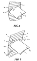
- auxiliary wing 4 shows a second embodiment of the auxiliary wing 4.
- the auxiliary wing 4 extends in this case from the surface of the blade 1 to the wall 2 and bridges thereby the corner 6. This configuration accelerates the corner flow particularly effective by acting as a nozzle.
- Fig. 5 shows a third embodiment in which the auxiliary wing 4 on the wall 2 in Transition area between the suction side 1a of the blade 1 and the wall 2 is arranged is.
- This auxiliary wing 4 has a slightly greater height than that on the blade attached auxiliary wings, since the boundary layer of the wall 2 is generally thicker.
- the auxiliary wing attached to wall 2 also protrudes into the outside flow.
- auxiliary wing 4 Analogous to the modifications in FIGS. 2a, 2b and 3a to 3d, in the case of the Wall 2 attached auxiliary wing 4 corresponding configurations can be used. It is important in this context that the vortex 5 generated by the auxiliary wing 4 is a Direction of rotation, which on the blade surface of the suction side 1a of the Blade center is directed to the blade ends. This is the only way to get fast flowing fluid from the center of the blade or the outside flow into the corner area at risk of detachment directed. In order to obtain the same direction of rotation of the vortex 5, the auxiliary wing is 4 so against the flow that its leading edge 8 closer to The blade surface lies as the trailing edge 9.
- auxiliary wings 4 The mode of operation of the auxiliary wings 4 is explained below with reference to FIG. 6.
- To 6 is a flow around a blade 1 in the transition region shown between blade 1 and wall 2, in which the auxiliary wing according to the invention 4 is not used.
- a boundary layer forms on the wall 2, the speed of which is close to the wall is very low because the fluid is slowed down there by the wall friction.
- the auxiliary wing 4 avoids the detachment in the area 14 by the trained by it Vortex 5 leads rapidly flowing fluid into the area 14 This fluid can be due to cope with the higher kinetic energy of the pressure increase 13 without detaching.
- FIG. 6 schematically shows the buoyancy polar 16 of a blade 1 without auxiliary wing 4 compared to a buoyancy polar 17 of a blade 1 provided with an auxiliary wing 4.
- the buoyancy L is plotted on the abscissa and the resistance D of the respective blade is plotted on the ordinate.
- the buoyancy L increases by an amount L 1 while the resistance D 0 remains constant if an auxiliary wing 4 is provided on the blade 1 or on the wall 2.
- the resistance D of the blade with auxiliary wing 4 on wall 2 and / or blade surface is reduced by an amount D 1 compared to a blade 1 without auxiliary wing 4.
- the weight of the turbomachine is kept constant, the power conversion can be increased.
Landscapes
- Engineering & Computer Science (AREA)
- Mechanical Engineering (AREA)
- General Engineering & Computer Science (AREA)
- Physics & Mathematics (AREA)
- Fluid Mechanics (AREA)
- Geometry (AREA)
- Structures Of Non-Positive Displacement Pumps (AREA)
Description
- Fig. 1
- eine perspektivische Ansicht eines ersten Ausführungsbeispiels der erfindungsgemäßen Schaufel.
- Fig. 2a
- eine erste Abänderung des Ausführungsbeispiels der Fig. 1 in einer Ansicht entlang des Pfeils II der Fig. 1.
- Fig. 2b
- eine zweite Abänderung des Ausführungsbeispiels der Fig. 1 in einer Ansicht entlang des Pfeils II der Fig. 1.
- Fig. 3a
- eine Ansicht des ersten Ausführungsbeispiels der Fig. 1 entlang des Pfeiles III der Fig. 1.
- Fig. 3b
- eine dritte Abänderung des ersten Ausführungsbeispiels der Fig. 1 in einer Ansicht entlang Pfeil III.
- Fig. 3c
- eine vierte Abänderung des ersten Ausführungsbeispiels der Fig. 1 in einer Ansicht entlang Pfeil III.
- Fig. 3d
- eine fünfte Abänderung des ersten Ausführungsbeispiels der Fig. 1 in einer Ansicht entlang Pfeil III.
- Fig. 4
- ein zweites Ausführungsbeispiel der erfindungsgemäßen Schaufel mit Hilfsflügel in einer perspektivischen Ansicht.
- Fig. 5
- ein drittes Ausführungsbeispiel der erfindungsgemäßen Schaufel mit Hilfsflügel in einer perspektivischen Ansicht.
- Fig. 6
- eine perspektivische Ansicht zweier Schaufeln zur Erläuterung der Strömungsverhältnisse im Wand-Schaufel-Übergangsbereich.
- Fig. 7
- eine Darstellung von Auftriebspolaren von Schaufeln mit und ohne Hilfsflügeln.
Claims (29)
- Schaufelanordnung für eine Strömungsmaschine, beispielsweise einen Verdichter, eine Pumpe oder eine Turbine mit einer Schaufel und mindestens einer Wand, wobei sich die Schaufel von der Wand in die Strömung erstreckt und sich im Betrieb der Strömungsmaschine im Übergangsbereich zwischen Wand und Schaufel eine Eckenströmung ausbildet, dadurch gekennzeichnet, daß die Oberfläche der Schaufel (1) und/oder der Wand (2) im Bereich der Eckenströmung mit zumindest einem gegenüber der Schaufel (1) kleinen, sich von der Oberfläche der Schaufel (1) und/oder der Wand (2) weg in die Strömung (3) erstreckendem Hilfsflügel (4) versehen ist, der gegen die an dieser Stelle herrschende Strömung angestellt ist, wobei sich im Betrieb der Strömungsmaschine im Nachlauf des Hilfsflügels (4) ein Wirbel (5) bildet, dessen Drehsinn so gerichtet ist, daß auf der dem Hilfsflügel (4) zugeordneten Schaufeloberfläche eine Geschwindigkeit von der Schaufelmitte hin zum Übergangsbereich von Wand (2) und Schaufel (1) induziert ist.
- Schaufelanordnung nach Anspruch 1, dadurch gekennzeichnet, daß eine stromauf weisende Anströmkante (8) des Hilfsflügels (4) in einem anderen Abstand von einer von Schaufel (1) und Wand (2) gebildeten Ecke angeordnet ist als eine stromab weisende Abströmkante (9) des Hilfsflügels (4).
- Schaufelanordnung nach einem der Ansprüche 1 und 2, dadurch gekennzeichnet, daß die Abströmkante (9) des auf der Schaufel (1) angeordneten Hilfsflügels (4) von der Wand (2) geringer beabstandet ist als die Anströmkante (8).
- Schaufelanordnung nach einem der obengenannten Änsprüche, dadurch gekennzeichnet, daß die Änströmkante (8) des an der Wand (2) angeordneten Hilfsflügels (4) von der Oberfläche der Schaufel (1) geringer beabstandet ist als die Äbströmkante (9).
- Schaufelanordnung nach einem der obengenannten Ansprüche, dadurch gekennzeichnet, daß eine Höhe des Hilfsflügels (4) in einer Richtung senkrecht zur Oberfläche der Schaufel (1) mindestens einer Grenzschichtdicke der Schaufelumströmung an der Stelle des Hilfsflügels (4) entspricht.
- Schaufelanordnung nach einem der obengenannten Ansprüche, dadurch gekennzeichnet, daß eine Höhe des Hilfsflügels in einer Richtung senkrecht zur Oberfläche der Wand (2) mindestens einer Grenzschichtdicke der Wandströmung an der Stelle des Hilfsflügels (4) entspricht.
- Schaufelanordnung nach einem der obengenannten Ansprüche, dadurch gekennzeichnet, daß sich der Hilfsflügel im wesentlichen senkrecht von der Oberfläche der Schaufel (1) und/oder der Wand (2) in die Strömung erstreckt.
- Schaufelanordnung nach einem der obengenannten Ansprüche, dadurch gekennzeichnet, daß sich der Hilfsflügel (4) von der Oberfläche der Schaufel (1) aus in Richtung der Wand (2) erstreckt.
- Schaufelanordnung nach einem der obengenannten Ansprüche, dadurch gekennzeichnet, daß sich der Hilfsflügel (4) von der Oberfläche der Wand (2) aus in Richtung der Schaufel (1) erstreckt.
- Schaufelanordnung nach einem der obengenannten Ansprüche, dadurch gekennzeichnet, daß der Hilfsflügel (4) auf der Oberfläche der Schaufel (1) in einem Abstand von der Wand (2) angeordnet ist, der 5% bis 30% der Schaufeltiefe entspricht.
- Schaufelanordnung nach einem der obengenannten Ansprüche, dadurch gekennzeichnet, daß der Hilfsflügel (4) auf der Oberfläche der Wand (2) in einem Abstand von der Oberfläche der Schaufel (1) angeordnet ist, der 5% bis 30% der Schaufeltiefe entspricht.
- Schaufelanordnung nach einem der obengenannten Ansprüche, dadurch gekennzeichnet, daß der Hilfsflügel (4) an der Saugseite (1a) der Schaufel (1) angeordnet ist.
- Schaufelanordnung nach einem der obengenannten Ansprüche, dadurch gekennzeichnet, daß der Hilfsflügel (4) im wesentlichen plattenförmig ausgestaltet ist.
- Schaufelanordnung nach einem der obengenannten Ansprüche, dadurch gekennzeichnet, daß der Hilfsflügel (4) in Form einer, vorzugsweise schwach, gewölbten Platte ausgestaltet ist.
- Schaufelanordnung nach einem der obengenannten Ansprüche, dadurch gekennzeichnet, daß der Hilfsflügel (4) ein einem Tragflügel ähnliches Dickenprofil aufweist.
- Schaufelanordnung nach einem der obengenannten Ansprüche, dadurch gekennzeichnet, daß die Länge des Hilfsflügels in Richtung der Strömung mindestens einer Höhe des an der Schaufeloberfläche angeordneten Hilfsflügels senkrecht zur Schaufeloberfläche oder des an der Wand (2) angeordneten Flügels senkrecht zur Wand entspricht.
- Schaufelanordnung nach einem der obengenannten Ansprüche, dadurch gekennzeichnet, daß der Hilfsflügel (4) mit einem Anstellwinkel (A) zwischen 3° und 30°, vorzugsweise zwischen 5° und 15°, gegen die Strömung an der Stelle des Hilfsflügels (4) angestellt ist.
- Schaufelanordnung nach einem der obengenannten Ansprüche, dadurch gekennzeichnet, daß der Hilfsflügel (4) in einem vorderen Bereich, vorzugsweise in der vorderen Hälfte, des Tragflügels oder an einem auf dieser Höhe liegenden Bereichs der Wand angeordnet ist.
- Schaufelanordnung nach einem der obengenannten Ansprüche, dadurch gekennzeichnet, daß der Umriß des Hilfsflügels (4) in Blickrichtung senkrecht zur Strömungsrichtung an der Stelle des Hilfsflügels im wesentlichen dreieckig ist.
- Schaufelanordnung nach einem der obengenannten Ansprüche, dadurch gekennzeichnet, daß der Umriß des Hilfsflügels (4) in Blickrichtung senkrecht zur Richtung der Schaufelumströmung an der Stelle des Hilfsflügels (4) im wesentlichen rechteckig ist.
- Schaufelanordnung nach einem der obengenannten Ansprüche, dadurch gekennzeichnet, daß die Anströmkante (8) des Hilfsflügels (4) gerade oder gekrümmt ist.
- Schaufelanordnung nach einem der obengenannten Ansprüche, dadurch gekennzeichnet, daß der Hilfsflügel (4) aus einem Blech gefertigt ist.
- Schaufelanordnung nach einem der obengenannten Ansprüche, dadurch gekennzeichnet, daß der Hilfsflügel (4) an der Oberfläche der Schaufel (1) oder der Wand (2) durch ein thermisches Fügeverfahren, wie beispielsweise Schweißen oder Hartlöten, befestigt ist oder mit der Schaufel (1) oder der Wand (2) verschraubt oder vernietet ist oder verklebt ist
- Schaufelanordnung nach einem der obengenannten Ansprüche, dadurch gekennzeichnet, daß der Hilfsflügel (4) einstückig mit der Schaufel (1) oder der Wand (2), beispielsweise durch Schmieden und/oder Sintern und/oder Ausfräsen und/oder galvanisches Umformen wie Elektroerodieren, ausgeformt ist.
- Schaufelanordnung nach einem der obengenannten Ansprüche, dadurch gekennzeichnet, daß der Hilfsflügel (4) in einem Schutzüberzug (11) der Schaufel (1) integriert ist, der zur Schwingungsdämpfung oder als Korrosionsschutz über die Schaufel (1) gezogen ist.
- Schaufelanordnung nach einem der obengenannten Ansprüche, dadurch gekennzeichnet, daß sich der Hilfsflügel (4) brückenförmig von der Oberfläche der Schaufel (1) zur Wand (2) erstreckt.
- Schaufelanordnung nach einem der oben genannten Ansprüche, dadurch gekennzeichnet, daß die Schaufel (1) an einer Nabe (2a) befestigt ist, wobei die Wand (2) von der Nabe (2a) gebildet ist.
- Schaufelanordnung nach einem der obengenannten Ansprüche, dadurch gekennzeichnet, daß die Schaufel (1) zwischen einer Nabe (2a) und einem Gehäuse (2b) angeordnet ist.
- Schaufelanordnung nach einem der obengenannten Anspürche, dadurch gekennzeichnet, daß die Schaufel (1) Teil eines Laufrades oder eines Leitrades ist.
Applications Claiming Priority (2)
| Application Number | Priority Date | Filing Date | Title |
|---|---|---|---|
| DE19834647 | 1998-07-31 | ||
| DE19834647A DE19834647C2 (de) | 1998-07-31 | 1998-07-31 | Schaufelanordnung für eine Strömungsmaschine |
Publications (3)
| Publication Number | Publication Date |
|---|---|
| EP0976928A2 EP0976928A2 (de) | 2000-02-02 |
| EP0976928A3 EP0976928A3 (de) | 2001-09-19 |
| EP0976928B1 true EP0976928B1 (de) | 2004-08-25 |
Family
ID=7876042
Family Applications (1)
| Application Number | Title | Priority Date | Filing Date |
|---|---|---|---|
| EP99114975A Expired - Lifetime EP0976928B1 (de) | 1998-07-31 | 1999-07-30 | Schaufelanordnung für eine Strömungsmaschine |
Country Status (2)
| Country | Link |
|---|---|
| EP (1) | EP0976928B1 (de) |
| DE (2) | DE19834647C2 (de) |
Families Citing this family (14)
| Publication number | Priority date | Publication date | Assignee | Title |
|---|---|---|---|---|
| EP1857635A1 (de) * | 2006-05-18 | 2007-11-21 | Siemens Aktiengesellschaft | Turbinenschaufel für eine Gasturbine |
| DE102008019740A1 (de) | 2008-04-19 | 2009-10-22 | Mtu Aero Engines Gmbh | Stator- und/oder Rotor-Stufe eines Axialverdichters einer Strömungsmaschine mit Strömungsleitelementen zur Wirkungsgradsteigerung |
| DE102008060424A1 (de) | 2008-12-04 | 2010-06-10 | Rolls-Royce Deutschland Ltd & Co Kg | Strömungsmaschine mit Seitenwand-Grenzschicht-Barriere |
| FR2939852B1 (fr) * | 2008-12-15 | 2014-10-31 | Snecma | Etage d'aubes statoriques dans un compresseur |
| DE102009052142B3 (de) * | 2009-11-06 | 2011-07-14 | MTU Aero Engines GmbH, 80995 | Axialverdichter |
| FR2987875B1 (fr) * | 2012-03-09 | 2015-08-21 | Snecma | Generateurs de vortex places dans le canal inter-aubes d'un redresseur de compresseur. |
| DE102012108975A1 (de) * | 2012-09-24 | 2014-03-27 | Firma IHI Charging Systems International GmbH | Verstellbarer Leitapparat für einen Abgasturbolader und Abgasturbolader |
| US9359900B2 (en) * | 2012-10-05 | 2016-06-07 | General Electric Company | Exhaust diffuser |
| EP2746534B1 (de) | 2012-12-19 | 2019-07-31 | MTU Aero Engines AG | Stator- und/oder Rotorstufe einer Strömungsmaschine, sowie zugehörige Gasturbine |
| DE102013224050B3 (de) * | 2013-08-23 | 2014-11-27 | Deutsches Zentrum für Luft- und Raumfahrt e.V. | Axialverdichter |
| BE1026579B1 (fr) * | 2018-08-31 | 2020-03-30 | Safran Aero Boosters Sa | Aube a protuberance pour compresseur de turbomachine |
| IT202100002240A1 (it) * | 2021-02-02 | 2022-08-02 | Gen Electric | Motore a turbine con palette a flusso trasversale ridotto |
| CN113562166B (zh) * | 2021-07-19 | 2023-03-28 | 中国人民解放军国防科技大学 | 一种流向拐角结构 |
| CN113548175B (zh) * | 2021-07-19 | 2022-12-02 | 中国人民解放军国防科技大学 | 一种流向拐角边界层角涡的控制装置和方法 |
Family Cites Families (6)
| Publication number | Priority date | Publication date | Assignee | Title |
|---|---|---|---|---|
| US3039736A (en) * | 1954-08-30 | 1962-06-19 | Pon Lemuel | Secondary flow control in fluid deflecting passages |
| US2920864A (en) * | 1956-05-14 | 1960-01-12 | United Aircraft Corp | Secondary flow reducer |
| BE638547A (de) * | 1962-10-29 | 1900-01-01 | ||
| US4023350A (en) * | 1975-11-10 | 1977-05-17 | United Technologies Corporation | Exhaust case for a turbine machine |
| DE3908285C1 (en) * | 1989-03-14 | 1990-06-07 | Daimler-Benz Aktiengesellschaft, 7000 Stuttgart, De | Turbine wheel of an exhaust turbocharger for an internal combustion engine with radial and/or mixed-flow gas feed |
| JPH094402A (ja) * | 1995-06-20 | 1997-01-07 | Mitsubishi Heavy Ind Ltd | 軸流タービンの翼列 |
-
1998
- 1998-07-31 DE DE19834647A patent/DE19834647C2/de not_active Expired - Lifetime
-
1999
- 1999-07-30 EP EP99114975A patent/EP0976928B1/de not_active Expired - Lifetime
- 1999-07-30 DE DE59910328T patent/DE59910328D1/de not_active Expired - Fee Related
Also Published As
| Publication number | Publication date |
|---|---|
| DE19834647C2 (de) | 2000-06-29 |
| DE59910328D1 (de) | 2004-09-30 |
| DE19834647A1 (de) | 2000-02-03 |
| EP0976928A3 (de) | 2001-09-19 |
| EP0976928A2 (de) | 2000-02-02 |
Similar Documents
| Publication | Publication Date | Title |
|---|---|---|
| DE102009052142B3 (de) | Axialverdichter | |
| DE69022405T2 (de) | Zentrifugalgebläse mit schaufeln mit variabler krümmung. | |
| DE69721114T3 (de) | Gekrümmte Gebläseschaufel | |
| EP1671030B1 (de) | Rotorblatt für eine windkraftanlage | |
| EP0990090B1 (de) | Rotor-schaufelblatt einer axialströmungsmaschine | |
| DE19834647C2 (de) | Schaufelanordnung für eine Strömungsmaschine | |
| EP2527642B1 (de) | Rotorblatt einer Windenergieanlage und entsprechendes Verfahren | |
| DE2852554A1 (de) | Rotor zum einsatz in einem stroemungsmedium | |
| EP0972128A1 (de) | Oberflächenstruktur für die wand eines strömungskanals oder einer turbinenschaufel | |
| WO2008046389A1 (de) | Anordnung zur strömungsbeeinflussung mittels grenzschichtbeeinflussender geometrien | |
| EP1642005B1 (de) | Turbinenschaufel | |
| DE202020005480U1 (de) | Wasserturbine | |
| DE4310104C2 (de) | Verfahren zur Reduzierung der Schallemission sowie zur Verbesserung der Luftleistung und des Wirkungsgrads bei einer axialen Strömungsmaschine und Strömungsmaschine | |
| EP2242923A2 (de) | Freistehende, tauchende wasserturbine mit einem axialrotor | |
| EP1759090A1 (de) | Schaufelblatt mit übergangszone | |
| DD288649A5 (de) | Radialventilator | |
| EP3231999A1 (de) | Leitschaufel mit filmgekühltem schaufelblatt | |
| DE102017129477A1 (de) | Strömungsoptimierter Seitenkanalverdichter und entsprechendes Schaufelrad | |
| EP4089264A1 (de) | Gasturbinen-schaufelanordnung | |
| DE102007005384A1 (de) | Strömungsarbeitsmaschine sowie Rotorschaufel einer Strömungsarbeitsmaschine | |
| DE102019220493A1 (de) | Gasturbinenschaufel | |
| DE102013224050B3 (de) | Axialverdichter | |
| EP4388180B1 (de) | Schaufel für eine strömungsmaschine sowie verfahren zur herstellung einer schaufel, wobei die schaufel eine schaufelspitze mit kerben auf einer anstreifschichtoberfläche aufweist | |
| DE102004053087B4 (de) | Wasser-Turbine oder -Pumpe oder -Pumpturbine | |
| DE322233C (de) | Laufrad fuer Wasserturbinen mit fluegelartigen Schaufeln |
Legal Events
| Date | Code | Title | Description |
|---|---|---|---|
| PUAI | Public reference made under article 153(3) epc to a published international application that has entered the european phase |
Free format text: ORIGINAL CODE: 0009012 |
|
| AK | Designated contracting states |
Kind code of ref document: A2 Designated state(s): AT BE CH CY DE DK ES FI FR GB GR IE IT LI LU MC NL PT SE Kind code of ref document: A2 Designated state(s): CH DE FR GB LI SE |
|
| AX | Request for extension of the european patent |
Free format text: AL;LT;LV;MK;RO;SI |
|
| PUAL | Search report despatched |
Free format text: ORIGINAL CODE: 0009013 |
|
| AK | Designated contracting states |
Kind code of ref document: A3 Designated state(s): AT BE CH CY DE DK ES FI FR GB GR IE IT LI LU MC NL PT SE |
|
| AX | Request for extension of the european patent |
Free format text: AL;LT;LV;MK;RO;SI |
|
| 17P | Request for examination filed |
Effective date: 20020104 |
|
| AKX | Designation fees paid |
Free format text: CH DE FR GB LI SE |
|
| 17Q | First examination report despatched |
Effective date: 20030314 |
|
| GRAP | Despatch of communication of intention to grant a patent |
Free format text: ORIGINAL CODE: EPIDOSNIGR1 |
|
| GRAS | Grant fee paid |
Free format text: ORIGINAL CODE: EPIDOSNIGR3 |
|
| GRAA | (expected) grant |
Free format text: ORIGINAL CODE: 0009210 |
|
| AK | Designated contracting states |
Kind code of ref document: B1 Designated state(s): CH DE FR GB LI SE |
|
| REG | Reference to a national code |
Ref country code: GB Ref legal event code: FG4D Free format text: NOT ENGLISH |
|
| REG | Reference to a national code |
Ref country code: CH Ref legal event code: NV Representative=s name: ISLER & PEDRAZZINI AG Ref country code: CH Ref legal event code: EP |
|
| GBT | Gb: translation of ep patent filed (gb section 77(6)(a)/1977) |
Effective date: 20040825 |
|
| REF | Corresponds to: |
Ref document number: 59910328 Country of ref document: DE Date of ref document: 20040930 Kind code of ref document: P |
|
| REG | Reference to a national code |
Ref country code: SE Ref legal event code: TRGR |
|
| ET | Fr: translation filed | ||
| PLBE | No opposition filed within time limit |
Free format text: ORIGINAL CODE: 0009261 |
|
| STAA | Information on the status of an ep patent application or granted ep patent |
Free format text: STATUS: NO OPPOSITION FILED WITHIN TIME LIMIT |
|
| 26N | No opposition filed |
Effective date: 20050526 |
|
| REG | Reference to a national code |
Ref country code: CH Ref legal event code: PCAR Free format text: ISLER & PEDRAZZINI AG;POSTFACH 1772;8027 ZUERICH (CH) |
|
| PGFP | Annual fee paid to national office [announced via postgrant information from national office to epo] |
Ref country code: DE Payment date: 20080704 Year of fee payment: 10 Ref country code: CH Payment date: 20080724 Year of fee payment: 10 |
|
| PGFP | Annual fee paid to national office [announced via postgrant information from national office to epo] |
Ref country code: FR Payment date: 20080718 Year of fee payment: 10 |
|
| PGFP | Annual fee paid to national office [announced via postgrant information from national office to epo] |
Ref country code: GB Payment date: 20080723 Year of fee payment: 10 |
|
| PGFP | Annual fee paid to national office [announced via postgrant information from national office to epo] |
Ref country code: SE Payment date: 20080724 Year of fee payment: 10 |
|
| REG | Reference to a national code |
Ref country code: CH Ref legal event code: PL |
|
| EUG | Se: european patent has lapsed | ||
| GBPC | Gb: european patent ceased through non-payment of renewal fee |
Effective date: 20090730 |
|
| REG | Reference to a national code |
Ref country code: FR Ref legal event code: ST Effective date: 20100331 |
|
| PG25 | Lapsed in a contracting state [announced via postgrant information from national office to epo] |
Ref country code: LI Free format text: LAPSE BECAUSE OF NON-PAYMENT OF DUE FEES Effective date: 20090731 Ref country code: FR Free format text: LAPSE BECAUSE OF NON-PAYMENT OF DUE FEES Effective date: 20090731 Ref country code: CH Free format text: LAPSE BECAUSE OF NON-PAYMENT OF DUE FEES Effective date: 20090731 |
|
| PG25 | Lapsed in a contracting state [announced via postgrant information from national office to epo] |
Ref country code: GB Free format text: LAPSE BECAUSE OF NON-PAYMENT OF DUE FEES Effective date: 20090730 |
|
| PG25 | Lapsed in a contracting state [announced via postgrant information from national office to epo] |
Ref country code: DE Free format text: LAPSE BECAUSE OF NON-PAYMENT OF DUE FEES Effective date: 20100202 |
|
| PG25 | Lapsed in a contracting state [announced via postgrant information from national office to epo] |
Ref country code: SE Free format text: LAPSE BECAUSE OF NON-PAYMENT OF DUE FEES Effective date: 20090731 |