EP0975951B1 - Feuchtigkeits-nachweis - Google Patents
Feuchtigkeits-nachweis Download PDFInfo
- Publication number
- EP0975951B1 EP0975951B1 EP98905147A EP98905147A EP0975951B1 EP 0975951 B1 EP0975951 B1 EP 0975951B1 EP 98905147 A EP98905147 A EP 98905147A EP 98905147 A EP98905147 A EP 98905147A EP 0975951 B1 EP0975951 B1 EP 0975951B1
- Authority
- EP
- European Patent Office
- Prior art keywords
- soil
- free fluid
- location
- collecting means
- moisture
- Prior art date
- Legal status (The legal status is an assumption and is not a legal conclusion. Google has not performed a legal analysis and makes no representation as to the accuracy of the status listed.)
- Expired - Lifetime
Links
- 238000001514 detection method Methods 0.000 title claims abstract description 24
- 239000012530 fluid Substances 0.000 claims abstract description 54
- 239000002689 soil Substances 0.000 claims abstract description 48
- 238000013022 venting Methods 0.000 claims abstract description 3
- 238000000034 method Methods 0.000 claims description 15
- 239000003621 irrigation water Substances 0.000 claims description 6
- 239000002245 particle Substances 0.000 claims description 6
- 230000011664 signaling Effects 0.000 claims description 6
- 229920006395 saturated elastomer Polymers 0.000 abstract description 3
- XLYOFNOQVPJJNP-UHFFFAOYSA-N water Substances O XLYOFNOQVPJJNP-UHFFFAOYSA-N 0.000 description 49
- 238000003973 irrigation Methods 0.000 description 37
- 230000002262 irrigation Effects 0.000 description 36
- 229910001369 Brass Inorganic materials 0.000 description 12
- 239000010951 brass Substances 0.000 description 12
- 238000005381 potential energy Methods 0.000 description 12
- 239000011521 glass Substances 0.000 description 7
- 241000196324 Embryophyta Species 0.000 description 6
- 229920001971 elastomer Polymers 0.000 description 4
- 238000005259 measurement Methods 0.000 description 4
- 230000032258 transport Effects 0.000 description 4
- 230000004888 barrier function Effects 0.000 description 3
- 230000008859 change Effects 0.000 description 3
- 230000003247 decreasing effect Effects 0.000 description 3
- 235000015097 nutrients Nutrition 0.000 description 3
- 239000000523 sample Substances 0.000 description 3
- 235000010624 Medicago sativa Nutrition 0.000 description 2
- 240000004658 Medicago sativa Species 0.000 description 2
- 235000013339 cereals Nutrition 0.000 description 2
- 238000003967 crop rotation Methods 0.000 description 2
- 230000000694 effects Effects 0.000 description 2
- 238000012544 monitoring process Methods 0.000 description 2
- 238000002310 reflectometry Methods 0.000 description 2
- 230000004044 response Effects 0.000 description 2
- 150000003839 salts Chemical class 0.000 description 2
- 239000004576 sand Substances 0.000 description 2
- 239000000565 sealant Substances 0.000 description 2
- 229910002651 NO3 Inorganic materials 0.000 description 1
- NHNBFGGVMKEFGY-UHFFFAOYSA-N Nitrate Chemical compound [O-][N+]([O-])=O NHNBFGGVMKEFGY-UHFFFAOYSA-N 0.000 description 1
- 238000010521 absorption reaction Methods 0.000 description 1
- 239000003905 agrochemical Substances 0.000 description 1
- 239000000919 ceramic Substances 0.000 description 1
- HPNSNYBUADCFDR-UHFFFAOYSA-N chromafenozide Chemical compound CC1=CC(C)=CC(C(=O)N(NC(=O)C=2C(=C3CCCOC3=CC=2)C)C(C)(C)C)=C1 HPNSNYBUADCFDR-UHFFFAOYSA-N 0.000 description 1
- 239000004927 clay Substances 0.000 description 1
- 239000004020 conductor Substances 0.000 description 1
- 230000007423 decrease Effects 0.000 description 1
- 238000007865 diluting Methods 0.000 description 1
- 238000005516 engineering process Methods 0.000 description 1
- 239000003344 environmental pollutant Substances 0.000 description 1
- 238000002474 experimental method Methods 0.000 description 1
- 238000001914 filtration Methods 0.000 description 1
- 230000005484 gravity Effects 0.000 description 1
- 239000003673 groundwater Substances 0.000 description 1
- 238000003895 groundwater pollution Methods 0.000 description 1
- 229910052602 gypsum Inorganic materials 0.000 description 1
- 239000010440 gypsum Substances 0.000 description 1
- 230000006872 improvement Effects 0.000 description 1
- 238000012625 in-situ measurement Methods 0.000 description 1
- 230000003993 interaction Effects 0.000 description 1
- 238000002955 isolation Methods 0.000 description 1
- 238000009533 lab test Methods 0.000 description 1
- 238000004519 manufacturing process Methods 0.000 description 1
- 239000000463 material Substances 0.000 description 1
- 238000012986 modification Methods 0.000 description 1
- 230000004048 modification Effects 0.000 description 1
- 238000001956 neutron scattering Methods 0.000 description 1
- 239000000575 pesticide Substances 0.000 description 1
- 230000000704 physical effect Effects 0.000 description 1
- 239000004033 plastic Substances 0.000 description 1
- 231100000719 pollutant Toxicity 0.000 description 1
- 239000011148 porous material Substances 0.000 description 1
- 230000008569 process Effects 0.000 description 1
- 230000005855 radiation Effects 0.000 description 1
- 230000025508 response to water Effects 0.000 description 1
- 230000000717 retained effect Effects 0.000 description 1
- 238000005070 sampling Methods 0.000 description 1
- 239000004065 semiconductor Substances 0.000 description 1
- 238000001966 tensiometry Methods 0.000 description 1
- 238000009736 wetting Methods 0.000 description 1
Images

Classifications
-
- G—PHYSICS
- G01—MEASURING; TESTING
- G01N—INVESTIGATING OR ANALYSING MATERIALS BY DETERMINING THEIR CHEMICAL OR PHYSICAL PROPERTIES
- G01N33/00—Investigating or analysing materials by specific methods not covered by groups G01N1/00 - G01N31/00
- G01N33/24—Earth materials
- G01N33/246—Earth materials for water content
-
- A—HUMAN NECESSITIES
- A01—AGRICULTURE; FORESTRY; ANIMAL HUSBANDRY; HUNTING; TRAPPING; FISHING
- A01G—HORTICULTURE; CULTIVATION OF VEGETABLES, FLOWERS, RICE, FRUIT, VINES, HOPS OR SEAWEED; FORESTRY; WATERING
- A01G25/00—Watering gardens, fields, sports grounds or the like
- A01G25/16—Control of watering
- A01G25/167—Control by humidity of the soil itself or of devices simulating soil or of the atmosphere; Soil humidity sensors
-
- B—PERFORMING OPERATIONS; TRANSPORTING
- B05—SPRAYING OR ATOMISING IN GENERAL; APPLYING FLUENT MATERIALS TO SURFACES, IN GENERAL
- B05B—SPRAYING APPARATUS; ATOMISING APPARATUS; NOZZLES
- B05B12/00—Arrangements for controlling delivery; Arrangements for controlling the spray area
- B05B12/08—Arrangements for controlling delivery; Arrangements for controlling the spray area responsive to condition of liquid or other fluent material to be discharged, of ambient medium or of target ; responsive to condition of spray devices or of supply means, e.g. pipes, pumps or their drive means
- B05B12/12—Arrangements for controlling delivery; Arrangements for controlling the spray area responsive to condition of liquid or other fluent material to be discharged, of ambient medium or of target ; responsive to condition of spray devices or of supply means, e.g. pipes, pumps or their drive means responsive to conditions of ambient medium or target, e.g. humidity, temperature position or movement of the target relative to the spray apparatus
Definitions
- This invention relates to moisture detection.
- moisture is to be given a broad meaning and refers to fluids, particularly water, in a porous medium and/or the solutes contained therein.
- the invention has particular but not exclusive application to agricultural methods and apparatus for detecting when adequate irrigation has been applied to the soil and for illustrative purposes reference will be made to such application. However it will be appreciated that the invention may be utilised in other applications which involve the detection of moisture.
- Devices which can assist irrigators to apply water in accordance with plant requirements are known. These include sensors based on electric, thermal and matric suction measurements (gypsum blocks, thermal probes, capacitance probes and tensiometry), and dielectric or radiation absorption measurements (time domain reflectometry, neutron scattering). These sensors vary in their cost, robustness, accuracy and the complexity of operation.
- the present invention aims to provide an alternative to known methods and apparatus for detecting the arrival of moisture at a location.
- this invention resides broadly in a method of detecting the arrival of moisture at a location within, or below the root zone of a plant growing in, an unsaturated permeable soil or soil-like medium, characterised in that the method includes:
- the invention resides broadly in a detection assembly for detecting the arrival of moisture at a location within, or below the root zone of a plant growing in, an unsaturated permeable soil or soil-like medium, characterised in that the assembly includes:
- flow streamline refers to the trajectory followed by a fluid particle moving through a permeable medium.
- free fluid means fluid which has a free boundary and which is able to be poured.
- the method further includes providing a signal to above the permeable medium to indicate that rain or irrigation water has reached the location.
- the surface is upwardly concave.
- the surface is a funnel.
- the free fluid formed upon saturation within the permeable medium is collected in collection means at the base of the non-vertical surface.
- the presence of free fluid is detected by sensor means positioned in the collection means.
- the collecting means includes an air filled cavity.
- the detection assembly includes a housing supporting the funnel and forming a space therebetween, wherein the vent means vents the air filled cavity to the space.
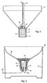
- the irrigation sensor of the present invention has a funnel-shaped container at the base of which is fixed a sensor having a conductivity cell.
- the container is a plastic funnel and a sintered glass cylinder is fixed within a brass cup at the base of the cone.
- the conductivity cell comprises a conductive brass cup and a conductive long brass pin, each of which is electrically isolated from the other.
- the pin is mounted on the inside of the sintered glass cylinder.
- brass cup 13 is located at the base of funnel-shaped container 11.
- Sintered glass cylinder 12 is located within brass cup 13.
- Rubber cap 17 plugs the upper end of the sintered glass cylinder 12 and has holes drilled to accept brass pin 14 and vent tube 16.
- Electrical wires 18 are connected to brass cup 13 and brass pin 14.
- a waterproof sealant 15 is applied to rubber cap 17 to electrically isolate brass pin 14 and its electrical connection from the soil. Vent tube 16 extends to the soil surface.
- irrigation sensor 21 has a substantially wine-glass shaped container 20 to optimise the convergence of the flow into the container and minimise the loss due to capillarity.
- An apertured cylinder 23 is located in the base of wine-glass funnel 20 and sealed therein by a rubber cap 27 which plugs the lower end of the funnel.
- Plug 27 has holes drilled to accept brass pins 24 (which are illustrated in alignment in FIG 2 such that only one is visible) and vent tube 26. Electrical wires 28 are connected to brass pins 24.
- a porous medium 22 encapsulates cylinder 23 at the lower end of funnel 20.
- a waterproof sealant 25 is applied to rubber cap 27 across the base of funnel 20 to electrically isolate brass pins 24 and its electrical connection from moisture. Vent tube 26 extends into the space between funnel 20 and casing 29 which houses the assembly.
- vent 26 vents conductivity cell 23 to the air space between funnel 20 and outer casing 29. Consequently no part of the assembly protrudes to the surface thus avoiding mowing problems associated with the FIG 1 embodiment if located in a lawn.
- the containers may have a range of sizes to suit different soil types.
- one form of the invention may contain suction means to produce a suction within the porous cup.
- the suction may be periodically or continuously applied.
- the senor In use the sensor is placed towards the bottom of the plant root zone, and activates an alarm or a solenoid valve when the irrigation water has percolated to the required depth.
- the container is filled with soil and buried with the funnel opening upper-most and within or below the root zone of the crop.
- the irrigation rate is sufficient to produce a background potential energy above some minimum value, the soil at the base of the funnel reaches saturation and the water seeps through the porous cylinder to partially fill the conductivity cell.
- the air displaced as the water enters the conductivity cell passes to the surface through the vent tube in the case of the embodiment of FIG 1, or to the space between the funnel and its casing in the embodiment of FIG 2.
- the cell is activated immediately water is present in the cup and an alarm or water solenoid is activated to turn the irrigation off. Over a period of some hours as the soil dries, the water in the cell is withdrawn back into the soil by capillary suction and the sensor is reset ready for a future irrigation event.
- the output signal from the fluid detector may be connected to a microprocessor controlling the irrigation schedule or may be operated in isolation whereby the irrigator responds to an alarm by turning off the irrigation.
- FIGS 1 and 2 Whilst the operational principles underlying the broad aspects of the invention will be readily apparent, a more detailed explanation will now be given of the some theoretical and operational aspects of the two preferred embodiments of the inventions illustrated in FIGS 1 and 2. However these are not to be construed as limiting on the invention per se.
- the containers may have a range of sizes to suit different soil types.
- two parameters which determine performance are the maximum size of the container and its depth.
- the sides of the container converge to a relatively small area and that the container is upwardly concave thereby converging the flow to the bottom of the container.
- the sides of the container are inclined to the flow streamlines some distance away from the moisture detector.
- Moist soil is said to have negative potential energy because energy is required to extract the water tightly held by the soil particles. This energy can be measured as a suction in centimetres or millimetres of water. Thus a glass of water 5 cm deep is said to have a potential energy of +5 cm ie a positive energy equivalent to the depth of water. Soil which is saturated has an energy of 0 cm. Soil which is moist has a negative value.
- the detector trips when there is free water in the conductivity cell. If this tripping is operable to cease irrigation activities, the suction in the soil surrounding the moisture detector, ie background negative potential energy will be typical of values found above the wetting front during irrigation. There is thus a minimum background potential energy where the detector must trip.
- the minimum background potential energy required to produce saturation is dependant on container size and slightly dependant on soil type and container shape. It is determined by the process of streamline convergence about a buried object caused by the interaction of gravity and capillarity.
- An object inserted in a permeable medium will cause flow streamlines to distort. If the object has an upwards configuration, the streamlines will be distorted within the object and will converge. Where streamlines converge the fluid content is increased. The larger a specific object, the larger will be the increase in fluid content.
- Soil can transport moisture in any direction through capillary suction provided there are no impermeable barriers in the way, the moisture at any point moving at a rate depending on the spatial gradient in moisture content and the physical properties of the soil. If the spatial gradient is decreased by inserting a partial barrier between the moist and dry soil, transport due to capillarity will be decreased. Increasing the depth of the container decreases the transport of fluid by capillarity because the sides of the container are a partial barrier to flow.
- the dimensions of the containers in the illustrated preferred embodiments of the invention were chosen so that the increase in fluid content due to flow streamline convergence such that at the base of the container the fluid content is increased to the point of saturation.
- the moisture detectors of the preferred illustrated embodiments may be considered to potentiometers which "trip" at a particular energy potential.
- the minimum background negative potential energy must be less than approximately -10 cm. This is achieved in the preferred embodiments illustrated by a container having a funnel diameter of approximately 20 cm and a funnel depth of approximately 10 cm.
- the minimum background potential energy required to produce saturation is dependant on container size and slightly dependant on soil type and container shape. Except for very small containers it is generally less than the background potential energy obtained when a soil is irrigated with standard sprinkler or micro-irrigation technologies.
- the funnel is to be filled with the soil displaced when digging the hole to install the sensor.
- the funnel can be filled with other porous material which can change the response time of the detection assembly.
- the funnel can be filled with material of high conductivity and low water holding capacity to shorten the response time for shallow rooted crops.
- FIG 3 illustrates evolution of water content within a fine sand in a laboratory tank.
- the horizontal axis denotes time elapsed since the commencement of irrigation.
- the detector was buried at a depth of 50 cm and the water content determined using TDR. Irrigation was applied with a disk permeammeter at the rate of 8.4 litre per hour.
- Plot 1 is the water content measured near the base of the funnel
- plot 2 is the average water content in the layer between the surface and 45 cm depth
- plot 3 is the average water content in the zone between 55 and 125 cm depth.
- Dotted line 4 indicates the time when water was detected within the conductivity cell and when the irrigation was halted.
- Line 5 indicates the time when the last of the water in the conductivity cell was drawn back into the soil and the sensor reset.
- FIG 4 illustrates evolution of water content within a bed of lucerne grown in a clay soil.
- the abscissa axis denotes time elapsed since the commencement of irrigation.
- the detector was buried with the sensor at a depth of 57 cm and the water content determined using TDR. Irrigation was applied with an overhead micro-jet at the rate of 9.5 mm per hour.
- Plot 1 is the water content measured near the base of the funnel
- plot 2 is the average water content in the layer between the surface and 60 cm depth
- plot 3 is the average water content in the zone between 60 and 90 cm depth.
- Line 4 indicates the time when water was detected within the conductivity cell and when the irrigation was halted.
Landscapes
- Life Sciences & Earth Sciences (AREA)
- Engineering & Computer Science (AREA)
- Health & Medical Sciences (AREA)
- Chemical & Material Sciences (AREA)
- Medicinal Chemistry (AREA)
- Biochemistry (AREA)
- General Life Sciences & Earth Sciences (AREA)
- Geology (AREA)
- Remote Sensing (AREA)
- Environmental Sciences (AREA)
- Water Supply & Treatment (AREA)
- Food Science & Technology (AREA)
- Soil Sciences (AREA)
- Physics & Mathematics (AREA)
- Analytical Chemistry (AREA)
- Environmental & Geological Engineering (AREA)
- General Health & Medical Sciences (AREA)
- General Physics & Mathematics (AREA)
- Immunology (AREA)
- Pathology (AREA)
- Investigating Or Analyzing Materials By The Use Of Electric Means (AREA)
- Investigating Or Analyzing Materials By The Use Of Fluid Adsorption Or Reactions (AREA)
- Sampling And Sample Adjustment (AREA)
- Control Of Motors That Do Not Use Commutators (AREA)
- Liquid Crystal (AREA)
Claims (11)
- Verfahren zum Detektieren des Eintreffens von Feuchtigkeit an einem Ort innerhalb oder unter der Wurzelzone einer Pflanze, die in einem ungesättigten durchlässigen Boden oder bodenartigen Medium wächst, dadurch gekennzeichnet, daß das Verfahren enthält:an genanntem Ort Positionieren eines Stromlinienverformmittels (11) mit einer Fläche, die im Gebrauch zum Verformen der Stromlinien von Fluidpartikeln, die sich durch ungesättigten Boden an genanntem Ort bewegen, nicht vertikal verläuft, um eine Zunahme des Fluidgehalts zu bewirken und eine Sättigung an genanntem Ort zu bewirken, wodurch daselbst freies Fluid gebildet wird;Sammeln des freien Fluids in einem Sammelmittel (13) unter genannter Fläche, wobei ein Filtermittel (12) ein durchlässiges Medium im Stromlinienverformmittel (11) vom Sammelmittel (13) trennt und freies Fluid sich von dem durchlässigen Medium zu oder von dem Sammelmittel (13) in Abhängigkeit von der Feuchtigkeit des durchlässigen Mediums bewegen läßt, wobei das Sammelmittel (13) einen mit Luft gefüllten Hohlraum enthält, der von dem Boden durch das Filtermittel (12) getrennt ist, so daß das Sammelmittel (13) und das durchlässige Medium hydraulisch verbunden bleiben, wo nach Ansammlung von freiem Fluid in dem Sammelmittel (13) Luft daraus über eine im wesentlichen geradlinige Leitung (16) abgelassen wird, die sich im wesentlichen vertikal nach oben von genanntem Sammelmittel (13) zur Bodenoberfläche erstreckt;Detektieren des Vorhandenseins des im Sammelmittel (13) gesammelten freien Fluids, wobei die Detektion des Vorhandenseins des freien Fluids dadurch das Eintreffen von Feuchtigkeit an genanntem Ort anzeigt;Signalisieren des Vorhandenseins des freien Fluids an einen Ort über dem durchlässigen Medium zum Anzeigen des Eintreffens von Feuchtigkeit an genanntem Ort.
- Verfahren zum Detektieren des Eintreffens von Feuchtigkeit nach Anspruch 1 und enthaltend Liefern eines Signals an über dem durchlässigen Medium zum Anzeigen, das Regen- oder Bewässerungswasser genannten Ort erreicht hat.
- Verfahren zum Detektieren des Eintreffens von Feuchtigkeit nach Anspruch 1, dadurch gekennzeichnet, daß die Fläche aufwärts konkav ist.
- Verfahren zum Detektieren des Eintreffens von Feuchtigkeit nach Anspruch 1, dadurch gekennzeichnet, daß das bei Sättigung im durchlässigen Medium gebildete freie Fluid in dem Sammelmittel an der Basis der nichtvertikalen Fläche gesammelt wird.
- Verfahren zum Detektieren des Eintreffens von Feuchtigkeit nach Anspruch 4, dadurch gekennzeichnet, daß das Vorhandensein von freiem Fluid von einem Sensormittel (14) detektiert wird, das im Sammelmittel positioniert ist.
- Detektionsanordnung zum Detektieren des Eintreffens von Feuchtigkeit an einem Ort innerhalb oder unter der Wurzelzone einer Pflanze, die in einem ungesättigten durchlässigen Boden oder bodenartigen Medium wächst, dadurch gekennzeichnet, daß die Anordnung enthält:wobei das Sammelmittel einen mit Luft gefüllten Hohlraum enthält, der vom Boden durch genanntes Filtermittel getrennt ist, so daß hydraulische Kontinuität zwischen dem mit Luft gefüllten Hohlraum und dem durchlässigen Medium aufrechterhalten wird.ein Stromlinienverformmittel (11) mit einer Fläche, die im Gebrauch zum Verformen der Stromlinien von Fluidpartikeln, die sich durch ungesättigten Boden an genanntem Ort bewegen, nicht vertikal verläuft, um eine Zunahme des Fluidgehalts zu bewirken und Sättigung an genanntem Ort zu bewirken, wodurch daselbst freies Fluid gebildet wird;ein Sammelmittel (13) unter genannter Fläche zum Sammeln genannten freien Fluids;eine im wesentlichen geradlinige Leitung (16), die sich im wesentlichen vertikal nach oben von genanntem Sammelmittel zur Bodenoberfläche zum Ablassen von Luft aus genanntem Sammelmittel (13) nach der Ansammlung von freiem Fluid darin erstreckt;ein Filtermittel (12), das ein durchlässiges Medium im Stromlinienverformmittel (11) vom Sammelmittel (13) trennt und freies Fluid sich vom durchlässigen Medium zu oder von dem Sammelmittel in Abhängigkeit von der Feuchtigkeit des durchlässigen Mediums bewegen läßt;ein Detektionsmittel (14) zum Detektieren des Vorhandenseins des im Sammelmittel gesammelten freien Fluids, wobei die Detektion des Vorhandenseins des freien Fluids dadurch das Eintreffen von Feuchtigkeit an genanntem Ort anzeigt; undein Signalisiermittel (18) zum Signalisieren des Vorhandenseins des freien Fluids an einen Ort über dem durchlässigen Medium zum Anzeigen, das Regen- oder Bewässerungswasser genannte Tiefe erreicht hat,
- Detektionsanordnung nach Anspruch 6, dadurch gekennzeichnet, daß genannte Fläche aufwärts konkav ist.
- Detektionsanordnung nach Anspruch 7, dadurch gekennzeichnet, daß genannte Fläche ein Trichter ist.
- Detektionsanordnung nach Anspruch 8, dadurch gekennzeichnet, daß genanntes Sammelmittel einen mit Luft gefüllten Hohlraum enthält.
- Detektionsanordnung nach Anspruch 8 und enthaltend ein Gehäuse (29), das genannten Trichter hält und dazwischen einen Raum bildet, worin genanntes Entlüftungsmittel genannten mit Luft gefüllten Hohlraum zu genanntem Raum entlüftet.
- Detektionsanordnung nach Anspruch 6, dadurch gekennzeichnet, daß genanntes Detektionsmittel ein Sensormittel enthält, das im Sammelmittel positioniert ist.
Applications Claiming Priority (5)
| Application Number | Priority Date | Filing Date | Title |
|---|---|---|---|
| AUPO540897 | 1997-02-28 | ||
| AUPO5408A AUPO540897A0 (en) | 1997-02-28 | 1997-02-28 | Moisture detection |
| AUPO9775A AUPO977597A0 (en) | 1997-10-13 | 1997-10-13 | Moisture detection |
| AUPO977597 | 1997-10-13 | ||
| PCT/AU1998/000128 WO1998038491A1 (en) | 1997-02-28 | 1998-02-24 | Moisture detection |
Publications (3)
| Publication Number | Publication Date |
|---|---|
| EP0975951A1 EP0975951A1 (de) | 2000-02-02 |
| EP0975951A4 EP0975951A4 (de) | 2001-06-13 |
| EP0975951B1 true EP0975951B1 (de) | 2004-06-09 |
Family
ID=25645370
Family Applications (1)
| Application Number | Title | Priority Date | Filing Date |
|---|---|---|---|
| EP98905147A Expired - Lifetime EP0975951B1 (de) | 1997-02-28 | 1998-02-24 | Feuchtigkeits-nachweis |
Country Status (7)
| Country | Link |
|---|---|
| US (1) | US6532803B2 (de) |
| EP (1) | EP0975951B1 (de) |
| AT (1) | ATE268900T1 (de) |
| DE (1) | DE69824406T2 (de) |
| ES (1) | ES2223122T3 (de) |
| PT (1) | PT975951E (de) |
| WO (1) | WO1998038491A1 (de) |
Families Citing this family (14)
| Publication number | Priority date | Publication date | Assignee | Title |
|---|---|---|---|---|
| IL141780A (en) * | 2001-03-04 | 2006-10-31 | C I T Controlled Irrigation Te | System and method for optimizing irrigation cycles |
| WO2003099454A2 (en) * | 2002-05-22 | 2003-12-04 | University Of Florida | Automatic control method system for irrigation |
| WO2004005628A2 (en) * | 2002-06-24 | 2004-01-15 | Arichell Technologies, Inc. | Automated water delivery systems with feedback control |
| DE10255605B4 (de) * | 2002-11-28 | 2005-07-07 | Infineon Technologies Ag | Reflektionsmaske zur Projektion einer Struktur auf einen Halbleiterwafer sowie Verfahren zu deren Herstellung |
| AU2004257492B2 (en) * | 2003-07-23 | 2011-04-14 | C.I.T. Controlled Irrigation Technologies Ltd. | Adaptive irrigation of vegetation |
| US7271729B2 (en) * | 2004-07-15 | 2007-09-18 | Rice Frank M | Novelty moisture detector for plants |
| US7836910B2 (en) * | 2004-12-29 | 2010-11-23 | Rain Bird Corporation | Soil moisture sensor and controller |
| US7437957B2 (en) | 2006-08-15 | 2008-10-21 | Hortau Inc. | Porous medium tensiometer |
| BR112012004673B1 (pt) * | 2009-09-03 | 2021-02-02 | Rubicon Research Pty Ltd | método para determinar o nível de superfície de uma área sujeita a irrigação por alagamento, sulcamento ou de superfície e método para determinar o volume de água de uma área sujeita a irrigação por alagamento, sulcamento ou de superfície |
| CN102230966A (zh) * | 2009-10-20 | 2011-11-02 | 鸿富锦精密工业(深圳)有限公司 | 声波感应监控及定位装置与方法 |
| CN102141503B (zh) * | 2011-01-06 | 2013-07-31 | 西安理工大学 | 雨水花园填料渗透系数的测试装置及测试方法 |
| GB201110550D0 (en) * | 2011-06-22 | 2011-08-03 | Delta T Devices Ltd | Matric potential sensor and related methods |
| US10955402B2 (en) * | 2016-06-19 | 2021-03-23 | Urban-Gro, Inc. | Modular sensor architecture for soil and water analysis at various depths from the surface |
| AU2022202306A1 (en) * | 2021-04-11 | 2022-10-27 | GrowOp World Ltd. | System for saturating a medium |
Family Cites Families (26)
| Publication number | Priority date | Publication date | Assignee | Title |
|---|---|---|---|---|
| US2776860A (en) * | 1955-02-21 | 1957-01-08 | Merle V Griffis | Automatic sprinkling device |
| GB883184A (en) * | 1959-03-17 | 1961-11-22 | Ronald Charles Frampton | Improvements in electrically-operated liquid supply regulating apparatus |
| US3297254A (en) * | 1964-08-06 | 1967-01-10 | Alfred C Coffman | Rain-controlled lawn sprinkler |
| US3908385A (en) * | 1972-06-16 | 1975-09-30 | Purdue Research Foundation | Planted surface conditioning system |
| GB1397315A (en) * | 1972-08-14 | 1975-06-11 | Haldor Topsoe As | Process for catalytic steam cracking |
| US3823874A (en) * | 1973-04-13 | 1974-07-16 | H Kroeck | Control for lawn sprinkler |
| US4155042A (en) * | 1977-10-31 | 1979-05-15 | Permut Alan R | Disaster alert system |
| FR2418623A1 (fr) * | 1978-03-02 | 1979-09-28 | Gaury Roger | Robot d'arrosage |
| US4396149A (en) * | 1980-12-30 | 1983-08-02 | Energy Management Corporation | Irrigation control system |
| US4693419A (en) * | 1981-11-02 | 1987-09-15 | Water Sentry, Inc. | Automatic control apparatus and method for sprinkling water over a predetermined area |
| US4541446A (en) * | 1983-03-31 | 1985-09-17 | Hogan Frank C | In-ground control unit for watering systems |
| JPS6098919A (ja) * | 1983-11-02 | 1985-06-01 | 湖南精工株式会社 | 自動散水制御装置 |
| US4718446A (en) * | 1986-04-15 | 1988-01-12 | Simpson Bobby R | Time and moisture-responsive sprinkler control system |
| US4952868A (en) * | 1986-05-19 | 1990-08-28 | Scherer Iii Robert P | Moisture sensing system for an irrigation system |
| US4947888A (en) * | 1989-06-13 | 1990-08-14 | Thomas Tanner | Toxic fluid and vapor handling apparatus |
| US5060859A (en) * | 1990-01-11 | 1991-10-29 | The Toro Company | Irrigation control apparatus responsive to soil moisture |
| FR2663129B1 (fr) | 1990-06-12 | 1993-01-29 | Oneill Andre | Pluviometre a reservoir intermediaire. |
| GB9019377D0 (en) * | 1990-09-05 | 1990-10-17 | Hettiaratchi Daniel B P | Irrigation sensor device |
| IL103334A0 (en) * | 1991-10-04 | 1993-03-15 | Robert Sydney Crook | Pump control system |
| GB2264259B (en) | 1992-02-24 | 1995-12-20 | Rankins | Laminated glazing material |
| US5179347A (en) * | 1992-04-10 | 1993-01-12 | Irrometer Company, Inc. | Electrical sensor for sensing moisture in soils |
| US5677499A (en) * | 1992-04-24 | 1997-10-14 | Oceanit Laboratories, Inc. | Lysimeter for collecting chemical samples from the vadose zone |
| US5337777A (en) * | 1992-10-08 | 1994-08-16 | Shaw David C H | Automatic sprinkler control override apparatus |
| US5419655A (en) * | 1993-08-02 | 1995-05-30 | Westinghouse Electric Corporation | Collection of liquid from below-ground location |
| US5546974A (en) * | 1995-01-03 | 1996-08-20 | Bireley; Richard L. | Moisture monitoring system |
| US5644947A (en) * | 1995-01-19 | 1997-07-08 | Lockheed Idaho Technologies Company | Tensiometer and method of determining soil moisture potential in below-grade earthen soil |
-
1998
- 1998-02-24 ES ES98905147T patent/ES2223122T3/es not_active Expired - Lifetime
- 1998-02-24 AT AT98905147T patent/ATE268900T1/de not_active IP Right Cessation
- 1998-02-24 EP EP98905147A patent/EP0975951B1/de not_active Expired - Lifetime
- 1998-02-24 PT PT98905147T patent/PT975951E/pt unknown
- 1998-02-24 DE DE69824406T patent/DE69824406T2/de not_active Expired - Fee Related
- 1998-02-24 WO PCT/AU1998/000128 patent/WO1998038491A1/en not_active Ceased
-
1999
- 1999-08-27 US US09/384,920 patent/US6532803B2/en not_active Expired - Fee Related
Also Published As
| Publication number | Publication date |
|---|---|
| PT975951E (pt) | 2004-09-30 |
| US20020066305A1 (en) | 2002-06-06 |
| DE69824406D1 (de) | 2004-07-15 |
| EP0975951A4 (de) | 2001-06-13 |
| WO1998038491A1 (en) | 1998-09-03 |
| EP0975951A1 (de) | 2000-02-02 |
| DE69824406T2 (de) | 2005-06-16 |
| ES2223122T3 (es) | 2005-02-16 |
| US6532803B2 (en) | 2003-03-18 |
| ATE268900T1 (de) | 2004-06-15 |
Similar Documents
| Publication | Publication Date | Title |
|---|---|---|
| EP0975951B1 (de) | Feuchtigkeits-nachweis | |
| US7042234B2 (en) | Soil matric potential and salinity measurement apparatus and method of use | |
| AU2005326399B2 (en) | Device for measuring thermal properties in a medium and method for determining the moisture content in the medium | |
| Miyata et al. | Surface runoff as affected by soil water repellency in a Japanese cypress forest | |
| CN107525756B (zh) | 一种土壤分层特征获取方法及应用 | |
| Poss et al. | amplers io meas leaching | |
| Richter et al. | A microlysimeter field study of solute transport through a structured sandy loam soil | |
| AU728070B2 (en) | Moisture detection | |
| JPH01182753A (ja) | 土壌水分測定装置 | |
| CN1361420A (zh) | 土壤溶液离子原态—原位测定系统 | |
| Stirzaker | Factors affecting sensitivity of wetting front detectors | |
| Meshkat et al. | COMPARISON OFWATER AND TEMPERATURE DISTRIBUTION PROFILES UNDER SAND TUBE IRRIGATION | |
| CN109269827A (zh) | 一种种植环境检测用的取样装置 | |
| CN214252267U (zh) | 用于水田等土壤表面具有浅层积水环境的蒸散测定系统 | |
| AU2003268594B2 (en) | Soil matric potential and salinity measurement apparatus and method of use | |
| Jabro et al. | Passive capillary sampler for measuring soil water drainage and flux in the vadose zone: Design, performance, and enhancement | |
| Rutter | Studies in the water relations of Pinus sylvestris in plantation conditions. II. The annual cycle of soil moisture change and derived estimates of evaporation | |
| CN223538813U (zh) | 土壤水分传感器现场在线标定系统 | |
| CN107509613B (zh) | 一种地下自感应一体式灌溉装置 | |
| CN221899180U (zh) | 一种农田土壤淋溶液的监测系统 | |
| Prathapar et al. | Effect of cultivation on the relationship between root length density and unsaturated hydraulic conductivity in a moderately swelling clay soil | |
| AU2003240312B2 (en) | A soil moisture sampling device and method | |
| Shukla et al. | Measurement of soil properties and surface hydrology parameters to assess the variation induced by different plantations | |
| Eymar et al. | Continuous measurements of electrical conductivity in growing media using a modified suction probe: Initial calibration and potential usefulness | |
| EP3531103A1 (de) | Extraktor, probenahmesystem damit und verfahren zu dessen verwendung |
Legal Events
| Date | Code | Title | Description |
|---|---|---|---|
| PUAI | Public reference made under article 153(3) epc to a published international application that has entered the european phase |
Free format text: ORIGINAL CODE: 0009012 |
|
| 17P | Request for examination filed |
Effective date: 19990924 |
|
| AK | Designated contracting states |
Kind code of ref document: A1 Designated state(s): AT BE CH DE DK ES FI FR GB GR IE IT LI LU MC NL PT SE |
|
| A4 | Supplementary search report drawn up and despatched |
Effective date: 20010502 |
|
| AK | Designated contracting states |
Kind code of ref document: A4 Designated state(s): AT BE CH DE DK ES FI FR GB GR IE IT LI LU MC NL PT SE |
|
| 17Q | First examination report despatched |
Effective date: 20030203 |
|
| GRAP | Despatch of communication of intention to grant a patent |
Free format text: ORIGINAL CODE: EPIDOSNIGR1 |
|
| GRAS | Grant fee paid |
Free format text: ORIGINAL CODE: EPIDOSNIGR3 |
|
| GRAA | (expected) grant |
Free format text: ORIGINAL CODE: 0009210 |
|
| AK | Designated contracting states |
Kind code of ref document: B1 Designated state(s): AT BE CH DE DK ES FI FR GB GR IE IT LI LU MC NL PT SE |
|
| PG25 | Lapsed in a contracting state [announced via postgrant information from national office to epo] |
Ref country code: NL Free format text: LAPSE BECAUSE OF FAILURE TO SUBMIT A TRANSLATION OF THE DESCRIPTION OR TO PAY THE FEE WITHIN THE PRESCRIBED TIME-LIMIT Effective date: 20040609 Ref country code: LI Free format text: LAPSE BECAUSE OF FAILURE TO SUBMIT A TRANSLATION OF THE DESCRIPTION OR TO PAY THE FEE WITHIN THE PRESCRIBED TIME-LIMIT Effective date: 20040609 Ref country code: FI Free format text: LAPSE BECAUSE OF FAILURE TO SUBMIT A TRANSLATION OF THE DESCRIPTION OR TO PAY THE FEE WITHIN THE PRESCRIBED TIME-LIMIT Effective date: 20040609 Ref country code: CH Free format text: LAPSE BECAUSE OF FAILURE TO SUBMIT A TRANSLATION OF THE DESCRIPTION OR TO PAY THE FEE WITHIN THE PRESCRIBED TIME-LIMIT Effective date: 20040609 Ref country code: BE Free format text: LAPSE BECAUSE OF FAILURE TO SUBMIT A TRANSLATION OF THE DESCRIPTION OR TO PAY THE FEE WITHIN THE PRESCRIBED TIME-LIMIT Effective date: 20040609 Ref country code: AT Free format text: LAPSE BECAUSE OF FAILURE TO SUBMIT A TRANSLATION OF THE DESCRIPTION OR TO PAY THE FEE WITHIN THE PRESCRIBED TIME-LIMIT Effective date: 20040609 |
|
| REG | Reference to a national code |
Ref country code: GB Ref legal event code: FG4D |
|
| REG | Reference to a national code |
Ref country code: CH Ref legal event code: EP |
|
| REF | Corresponds to: |
Ref document number: 69824406 Country of ref document: DE Date of ref document: 20040715 Kind code of ref document: P |
|
| REG | Reference to a national code |
Ref country code: IE Ref legal event code: FG4D |
|
| PG25 | Lapsed in a contracting state [announced via postgrant information from national office to epo] |
Ref country code: SE Free format text: LAPSE BECAUSE OF FAILURE TO SUBMIT A TRANSLATION OF THE DESCRIPTION OR TO PAY THE FEE WITHIN THE PRESCRIBED TIME-LIMIT Effective date: 20040909 Ref country code: DK Free format text: LAPSE BECAUSE OF FAILURE TO SUBMIT A TRANSLATION OF THE DESCRIPTION OR TO PAY THE FEE WITHIN THE PRESCRIBED TIME-LIMIT Effective date: 20040909 |
|
| REG | Reference to a national code |
Ref country code: PT Ref legal event code: SC4A Free format text: AVAILABILITY OF NATIONAL TRANSLATION Effective date: 20040730 |
|
| REG | Reference to a national code |
Ref country code: GR Ref legal event code: EP Ref document number: 20040403019 Country of ref document: GR |
|
| NLV1 | Nl: lapsed or annulled due to failure to fulfill the requirements of art. 29p and 29m of the patents act | ||
| REG | Reference to a national code |
Ref country code: CH Ref legal event code: PL |
|
| REG | Reference to a national code |
Ref country code: ES Ref legal event code: FG2A Ref document number: 2223122 Country of ref document: ES Kind code of ref document: T3 |
|
| ET | Fr: translation filed | ||
| PG25 | Lapsed in a contracting state [announced via postgrant information from national office to epo] |
Ref country code: LU Free format text: LAPSE BECAUSE OF NON-PAYMENT OF DUE FEES Effective date: 20050224 Ref country code: IE Free format text: LAPSE BECAUSE OF NON-PAYMENT OF DUE FEES Effective date: 20050224 Ref country code: GB Free format text: LAPSE BECAUSE OF NON-PAYMENT OF DUE FEES Effective date: 20050224 |
|
| PG25 | Lapsed in a contracting state [announced via postgrant information from national office to epo] |
Ref country code: MC Free format text: LAPSE BECAUSE OF NON-PAYMENT OF DUE FEES Effective date: 20050228 |
|
| PLBE | No opposition filed within time limit |
Free format text: ORIGINAL CODE: 0009261 |
|
| STAA | Information on the status of an ep patent application or granted ep patent |
Free format text: STATUS: NO OPPOSITION FILED WITHIN TIME LIMIT |
|
| 26N | No opposition filed |
Effective date: 20050310 |
|
| GBPC | Gb: european patent ceased through non-payment of renewal fee |
Effective date: 20050223 |
|
| REG | Reference to a national code |
Ref country code: IE Ref legal event code: MM4A |
|
| PGFP | Annual fee paid to national office [announced via postgrant information from national office to epo] |
Ref country code: ES Payment date: 20090317 Year of fee payment: 12 |
|
| PGFP | Annual fee paid to national office [announced via postgrant information from national office to epo] |
Ref country code: PT Payment date: 20090219 Year of fee payment: 12 Ref country code: DE Payment date: 20090219 Year of fee payment: 12 |
|
| PGFP | Annual fee paid to national office [announced via postgrant information from national office to epo] |
Ref country code: GR Payment date: 20090123 Year of fee payment: 12 |
|
| PGFP | Annual fee paid to national office [announced via postgrant information from national office to epo] |
Ref country code: IT Payment date: 20090214 Year of fee payment: 12 |
|
| PGFP | Annual fee paid to national office [announced via postgrant information from national office to epo] |
Ref country code: FR Payment date: 20090213 Year of fee payment: 12 |
|
| REG | Reference to a national code |
Ref country code: PT Ref legal event code: MM4A Free format text: LAPSE DUE TO NON-PAYMENT OF FEES Effective date: 20100824 |
|
| REG | Reference to a national code |
Ref country code: FR Ref legal event code: ST Effective date: 20101029 |
|
| PG25 | Lapsed in a contracting state [announced via postgrant information from national office to epo] |
Ref country code: PT Free format text: LAPSE BECAUSE OF NON-PAYMENT OF DUE FEES Effective date: 20100824 Ref country code: FR Free format text: LAPSE BECAUSE OF NON-PAYMENT OF DUE FEES Effective date: 20100301 |
|
| PG25 | Lapsed in a contracting state [announced via postgrant information from national office to epo] |
Ref country code: DE Free format text: LAPSE BECAUSE OF NON-PAYMENT OF DUE FEES Effective date: 20100901 |
|
| REG | Reference to a national code |
Ref country code: ES Ref legal event code: FD2A Effective date: 20110330 |
|
| PG25 | Lapsed in a contracting state [announced via postgrant information from national office to epo] |
Ref country code: IT Free format text: LAPSE BECAUSE OF NON-PAYMENT OF DUE FEES Effective date: 20100224 |
|
| PG25 | Lapsed in a contracting state [announced via postgrant information from national office to epo] |
Ref country code: ES Free format text: LAPSE BECAUSE OF NON-PAYMENT OF DUE FEES Effective date: 20110317 |
|
| PG25 | Lapsed in a contracting state [announced via postgrant information from national office to epo] |
Ref country code: ES Free format text: LAPSE BECAUSE OF NON-PAYMENT OF DUE FEES Effective date: 20100225 |