EP0974751A2 - Dispositif d'arrêt d'un système d'injection de combustible - Google Patents
Dispositif d'arrêt d'un système d'injection de combustible Download PDFInfo
- Publication number
- EP0974751A2 EP0974751A2 EP99113548A EP99113548A EP0974751A2 EP 0974751 A2 EP0974751 A2 EP 0974751A2 EP 99113548 A EP99113548 A EP 99113548A EP 99113548 A EP99113548 A EP 99113548A EP 0974751 A2 EP0974751 A2 EP 0974751A2
- Authority
- EP
- European Patent Office
- Prior art keywords
- fuel injection
- lifter
- engine
- hydraulic
- slot
- Prior art date
- Legal status (The legal status is an assumption and is not a legal conclusion. Google has not performed a legal analysis and makes no representation as to the accuracy of the status listed.)
- Withdrawn
Links
- 239000000446 fuel Substances 0.000 title claims abstract description 78
- 238000002347 injection Methods 0.000 title claims abstract description 48
- 239000007924 injection Substances 0.000 title claims abstract description 48
- 239000012530 fluid Substances 0.000 claims abstract description 21
- 238000002485 combustion reaction Methods 0.000 claims abstract description 4
- 239000010687 lubricating oil Substances 0.000 claims description 4
- 239000003921 oil Substances 0.000 claims description 4
- 230000006978 adaptation Effects 0.000 description 2
- 238000012986 modification Methods 0.000 description 2
- 230000004048 modification Effects 0.000 description 2
- 230000003213 activating effect Effects 0.000 description 1
- 230000002401 inhibitory effect Effects 0.000 description 1
- 230000007257 malfunction Effects 0.000 description 1
Images

Classifications
-
- F—MECHANICAL ENGINEERING; LIGHTING; HEATING; WEAPONS; BLASTING
- F02—COMBUSTION ENGINES; HOT-GAS OR COMBUSTION-PRODUCT ENGINE PLANTS
- F02M—SUPPLYING COMBUSTION ENGINES IN GENERAL WITH COMBUSTIBLE MIXTURES OR CONSTITUENTS THEREOF
- F02M63/00—Other fuel-injection apparatus having pertinent characteristics not provided for in groups F02M39/00 - F02M57/00 or F02M67/00; Details, component parts, or accessories of fuel-injection apparatus, not provided for in, or of interest apart from, the apparatus of groups F02M39/00 - F02M61/00 or F02M67/00; Combination of fuel pump with other devices, e.g. lubricating oil pump
- F02M63/02—Fuel-injection apparatus having several injectors fed by a common pumping element, or having several pumping elements feeding a common injector; Fuel-injection apparatus having provisions for cutting-out pumps, pumping elements, or injectors; Fuel-injection apparatus having provisions for variably interconnecting pumping elements and injectors alternatively
- F02M63/0205—Fuel-injection apparatus having several injectors fed by a common pumping element, or having several pumping elements feeding a common injector; Fuel-injection apparatus having provisions for cutting-out pumps, pumping elements, or injectors; Fuel-injection apparatus having provisions for variably interconnecting pumping elements and injectors alternatively for cutting-out pumps or injectors in case of abnormal operation of the engine or the injection apparatus, e.g. over-speed, break-down of fuel pumps or injectors ; for cutting-out pumps for stopping the engine
- F02M63/021—Fuel-injection apparatus having several injectors fed by a common pumping element, or having several pumping elements feeding a common injector; Fuel-injection apparatus having provisions for cutting-out pumps, pumping elements, or injectors; Fuel-injection apparatus having provisions for variably interconnecting pumping elements and injectors alternatively for cutting-out pumps or injectors in case of abnormal operation of the engine or the injection apparatus, e.g. over-speed, break-down of fuel pumps or injectors ; for cutting-out pumps for stopping the engine by locking pump pistons
-
- F—MECHANICAL ENGINEERING; LIGHTING; HEATING; WEAPONS; BLASTING
- F01—MACHINES OR ENGINES IN GENERAL; ENGINE PLANTS IN GENERAL; STEAM ENGINES
- F01M—LUBRICATING OF MACHINES OR ENGINES IN GENERAL; LUBRICATING INTERNAL COMBUSTION ENGINES; CRANKCASE VENTILATING
- F01M1/00—Pressure lubrication
- F01M1/18—Indicating or safety devices
- F01M1/20—Indicating or safety devices concerning lubricant pressure
- F01M1/22—Indicating or safety devices concerning lubricant pressure rendering machines or engines inoperative or idling on pressure failure
- F01M1/24—Indicating or safety devices concerning lubricant pressure rendering machines or engines inoperative or idling on pressure failure acting on engine fuel system
-
- F—MECHANICAL ENGINEERING; LIGHTING; HEATING; WEAPONS; BLASTING
- F02—COMBUSTION ENGINES; HOT-GAS OR COMBUSTION-PRODUCT ENGINE PLANTS
- F02B—INTERNAL-COMBUSTION PISTON ENGINES; COMBUSTION ENGINES IN GENERAL
- F02B77/00—Component parts, details or accessories, not otherwise provided for
- F02B77/08—Safety, indicating, or supervising devices
-
- F—MECHANICAL ENGINEERING; LIGHTING; HEATING; WEAPONS; BLASTING
- F02—COMBUSTION ENGINES; HOT-GAS OR COMBUSTION-PRODUCT ENGINE PLANTS
- F02B—INTERNAL-COMBUSTION PISTON ENGINES; COMBUSTION ENGINES IN GENERAL
- F02B2275/00—Other engines, components or details, not provided for in other groups of this subclass
- F02B2275/34—Lateral camshaft position
Definitions
- the invention relates to a fuel injection engine and more particularly to a diesel engine with a fuel injection shutdown system, which will shut off the fuel to each cylinder within two engine revolutions.
- U.S. Patent 4,565,170 describes a device for shutting off the fuel supplied to the engine by utilizing a solenoid valve to shut off the fuel being supplied to the engine and activating an aspirating pump to remove fuel from the fuel manifold to shutdown the engine quickly.
- a fuel injection shutdown system for a fuel injected internal combustion engine having a plurality of cylinders and a mechanical fuel injector with a injector return spring for each cylinder cooperatively associated with a fuel injection cam disposed on a camshaft and lifter bodies that are reciprocated in lifter guides to inject fuel into each cylinder upon each revolution of the injection camshaft when made in accordance with this invention comprises a slot disposed in each lifter guide and a slot disposed in each lifter body.
- a hydraulic cartridge is disposed to fit into the slot in the lifter guide and be fastened thereto. The hydraulic cartridge extends into the slot in the lifter body.
- the slot in the lifter body is longer than the slot in the lifter guide and is disposed to allow the lifter body to be reciprocated by the fuel injection cam without the cartridge contacting the bottom or top of the slot in the lifter body.
- the hydraulic cartridge has a stop pin slidably disposed therein. A fluid passage disposed in the cartridge, when supplied with pressurized hydraulic fluid, causes the stop pin to extend from the cartridge and contact the top of the slot in the lifter body. The extended stop pin holds the lifter body off the fuel injection cam, whereby fuel injected into the engine will be discontinued within two engine revolutions and the engine will shutdown.
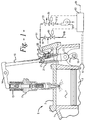
- FIG. 1 there is shown a portion of an engine block 1 and a cylinder head 3 of a fuel injected internal combustion engine 5 such as a diesel engine 5.
- a fuel injected internal combustion engine 5 such as a diesel engine 5.
- FIG. 1 a portion of a cylinder 7 and piston 9.
- a mechanical fuel injector 11 is disposed in the head 3 and extends into the cylinder 7 to inject the fuel.
- the fuel injector 11 has a return spring 13 that cooperates with a rocker arm 14 to bias a lifter rod 15 to engage a lifter body 19.
- the lifter body 19 engages a fuel injection cam 17 on fuel injection camshaft 18.
- the lifter body 19 is slidably disposed in a lifter guide 21 and has a cam follower roller 23 that engages the fuel injection cam 17 on the fuel injection camshaft 18. With each rotation of the fuel injection cam shaft 17, the fuel injector 11 associated with each cylinder 7 injects fuel into the associated cylinder 7 in a predetermined order to run the fuel injected engine 5.
- a fuel injection shutdown system that will stop supplying fuel to the engine 5 within one engine cycle or two revolutions of a four cycle engine comprises an elongated slot 25 disposed in each lifter guide 21 and an elongated slot 27 disposed in each lifter body 19.
- a hydraulic cartridge 29 is disposed to fit in the slot 25 in the lifter guide 21 and be fastened thereto by bolts or other fastening means (not shown) and to extend into the slot 27 in the lifter body 19.
- the slot 27 in the lifter body 19 is longer than the slot 25 in the lifter guide 21 and so disposed to allow the lifter body 19 to be reciprocated in the lifter guide 21 by the fuel injection cam 17 on the fuel injection camshaft 18 without the hydraulic cartridge 29 contacting the top or bottom of the slot 27.
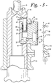
- the hydraulic cartridge 29 has a cylindrical opening 31 extending therein with a smaller diameter short lower portion 33.
- the cylindrical opening 31 is generally aligned with the slot 27 in the lifter body 19.
- a stop pin 35 is disposed in the cylindrical opening and has an enlarged lower portion 37 that forms a close sliding fit in the cylindrical opening 31.
- a spring 39 encircles the stop pin 35 and biases the stop pin 35 into the hydraulic cartridge 29.
- the spring 39 is held in place by a retainer ring 41 adjacent the open end of the cylindrical opening 31.
- the retainer is held in place by interlocking threads, a pressed fit or other means.
- the retainer ring 41 also provides a close fitting sliding bearing for the stop pin 35.
- a weep hole 43 is disposed adjacent the open end of the cylindrical opening 31 to prevent any oil which leaks into the cylindrical opening 31 from becoming trapped therein and inhibiting the movement of the stop pin 35.
- a hydraulic fluid accumulator 45 is disposed in the hydraulic cartridge 29 to damp pressure spikes during operation of the fuel injection shutdown system. The accumulator 45 is disposed in fluid communication with the lower portion 33 of the cylindrical opening 31 by a duct or passage 47 and has a port 49. The port 49 is disposed in fluid communication with a conduit 51, which is shown to have two branches. An up stream branch 51U has a check valve 53 adjacent the port 49, a supply solenoid valve 55 up stream of the check valve 53 and a pump 57 up stream of the solenoid valve 55.
- a down stream branch 51D has a bleed orifice 59 down stream of the port 49 and a bleed solenoid valve 61 down stream of the bleed orifice 59. While it is preferred to have the check valve 53 and bleed orifice 59 outside the hydraulic cartridge 29 they may be disposed within the cartridge 29. There is a separate check valve 53 and bleed orifice 59 for each cartridge while it is preferred to have a single supply and bleed solenoid valve 55 and 61 and a single pump 57.
- the stop pin 35 is shown in its normal position disposed wholly within the cartridge 29 allowing the lifter body 19to be moved up and down by the fuel injection cam 17 to operate the fuel injector 11, to inject fuel into the cylinders 7 and to operate the engine 5.
- FIG 3 it is the same as Figure 2 except the stop pin 35 is shown in its extended position contacting the top of the slot 27 in the lifter body 19 and holding the lifter body 19 off the fuel injection cam 17 thus preventing the fuel injector 11 from injecting fuel into the cylinder 7 stopping the engine 5.
- an electronic control module 63 receives signals from a plurality of engine sensors.
- electronic control module 63 receives a signal from an engine sensor 65, which sends a signal indicating that there has been a loss of oil pressure or a signal from an engine sensor 67, which sends a signal indicating that the engine is over speeding or any other signal or combination of signals indicative of a engine condition which will result in major damage to the engine if it continues to run
- the electronic control module 63 sends a signal to the supply solenoid 55 to open.
- the supply solenoid 55 opens, the pressurized fluid from the pump 57 opens the check valve 53 supplying pressurized fluid to the hydraulic cartridge 29.
- the pressurized fluid biases the stop pin 35 upwardly overcoming the bias of the spring 39 encircling the stop pin 35.
- the stop pin 35 moves upwardly until it contacts the top of the slot 27.
- the pressure of the pressurized fluid supplied by the pump 57 is insufficient to overcome the bias of the injector return spring 13, so the stop pin 35 will only reach its full extension, if the lifter body 19 is being lifted by the injection cam 17.
- the pressure in the hydraulic cartridge 29 builds up above the pressure supplied by the pump 57 and the check valve 53 closes.
- the trapped fluid in the hydraulic cartridge 29 increases in pressure to a pressure, which will equal the bias applied by the injector return spring 13 and hold the lifter body 19 at it maximum lifted position stopping the fuel injector 11 from injecting fuel into the cylinder 7. No fuel will be injected into any of the cylinders 7 after the injection camshaft 18 has made on revolution.
- a manual reset switch 69 is activated. This sends a signal to the electronic control module 63 to energize the solenoid valve 61 to open and allows the bleed orifice 59 associated with each hydraulic cartridge 29 to bleed down the fluid pressure in each hydraulic cartridge 29 at a controlled rate. A rate which will minimize the impact of the lifter body 19 reengaging the cam 17.
- Lubricating oil is the preferred hydraulic fluid, it may come from and return to a separate reservoir or a crankcase (neither of which are shown).
- the check valves 53 open when the supply pressure is generally about 10 psi higher than the pressure within the hydraulic cartridge 29 and close when the pressure within the hydraulic cartridge 26 is generally about 15 psi above the supply pressure.
- the bleed orifices 59 are preferably capillary type orifices with very small diameter openings extending a relatively long distance.
- a fuel injection shutdown system when made in accordance with this invention advantageously provides a shutdown system that will shut down a loaded engine in two revolutions when the engine's electronic control module receives a signal indicating that there has been a loss of oil pressure, the engine is over heated or any other signal that is indicative of a engine condition which will result in major damage to the engine if it continues to run. Stopping the engine rapidly protects the engine from major damage and greatly reduces costs of repair and down time on the engine.
Landscapes
- Engineering & Computer Science (AREA)
- Mechanical Engineering (AREA)
- General Engineering & Computer Science (AREA)
- Chemical & Material Sciences (AREA)
- Combustion & Propulsion (AREA)
- Output Control And Ontrol Of Special Type Engine (AREA)
- Fuel-Injection Apparatus (AREA)
Applications Claiming Priority (2)
| Application Number | Priority Date | Filing Date | Title |
|---|---|---|---|
| US119293 | 1998-07-20 | ||
| US09/119,293 US5878710A (en) | 1998-07-20 | 1998-07-20 | Fuel injection shutdown system |
Publications (2)
| Publication Number | Publication Date |
|---|---|
| EP0974751A2 true EP0974751A2 (fr) | 2000-01-26 |
| EP0974751A3 EP0974751A3 (fr) | 2003-02-05 |
Family
ID=22383609
Family Applications (1)
| Application Number | Title | Priority Date | Filing Date |
|---|---|---|---|
| EP99113548A Withdrawn EP0974751A3 (fr) | 1998-07-20 | 1999-07-06 | Dispositif d'arrêt d'un système d'injection de combustible |
Country Status (2)
| Country | Link |
|---|---|
| US (1) | US5878710A (fr) |
| EP (1) | EP0974751A3 (fr) |
Cited By (1)
| Publication number | Priority date | Publication date | Assignee | Title |
|---|---|---|---|---|
| DE19935211A1 (de) * | 1999-07-27 | 2001-02-01 | Deutz Ag | Hydraulischer Förderbeginn-Versteller |
Families Citing this family (7)
| Publication number | Priority date | Publication date | Assignee | Title |
|---|---|---|---|---|
| JPH08135462A (ja) * | 1994-11-09 | 1996-05-28 | Yamaha Motor Co Ltd | 縦型エンジン |
| US6604502B1 (en) * | 2000-09-27 | 2003-08-12 | Ford Global Technologies, Inc. | Method for controlling an internal combustion engine during engine shutdown to reduce evaporative emissions |
| DE10117094A1 (de) * | 2001-04-06 | 2002-10-17 | Bosch Gmbh Robert | Brennkraftmaschine mit einem Hydrauliksystem |
| ITTO20010980A1 (it) * | 2001-10-16 | 2003-04-16 | Lombardini Srl A Socio Unico | Impianto di alimentazione del combustibile per un motore ad iniezione. |
| JP3954918B2 (ja) * | 2002-07-26 | 2007-08-08 | 本田技研工業株式会社 | エンジンの燃料遮断装置 |
| US6886525B1 (en) * | 2003-10-15 | 2005-05-03 | Csxt Intellectual Properties Corporation | Locomotive engine with skipfire control system |
| TWI258123B (en) * | 2005-02-03 | 2006-07-11 | Lite On It Corp | Apparatus for positioning a clamper of a disc driver |
Family Cites Families (17)
| Publication number | Priority date | Publication date | Assignee | Title |
|---|---|---|---|---|
| US1949470A (en) * | 1929-10-24 | 1934-03-06 | Hesselman Knut Jonas Elias | Internal combustion engine |
| DE1136158B (de) * | 1959-11-17 | 1962-09-06 | Sulzer Ag | Sicherheitsabstellvorrichtung fuer Verbrennungsmotoren mit Brennstoffeinspritzung |
| US3638628A (en) * | 1970-09-18 | 1972-02-01 | Henry Stanford Stolworthy | Fuel control assembly for internal combustion engines having fuel injectors |
| DE2364969A1 (de) * | 1973-12-28 | 1975-07-03 | Ckd Praha | Hilfseinrichtung zur handbetaetigung des hebers einer einspritzpumpe bei dieselmotoren |
| US4020814A (en) * | 1975-05-30 | 1977-05-03 | Hewitt John T | Diesel engine control means |
| US4071010A (en) * | 1976-07-19 | 1978-01-31 | Caterpillar Tractor Co. | Engine start-up system and method |
| US4080946A (en) * | 1976-12-20 | 1978-03-28 | Lenmar Industries, Inc. | Internal combustion engine shut-down control valve |
| US4419977A (en) * | 1979-03-23 | 1983-12-13 | Eaton Corporation | Fuel injection system and timing advance device therefor |
| JPS57193729A (en) * | 1981-05-25 | 1982-11-29 | Nissan Motor Co Ltd | Fuel shutoff device of fuel injection pump |
| US4522569A (en) * | 1982-10-28 | 1985-06-11 | Mcgard, Inc. | Venting fuel valve for diesel engine fuel supply system |
| EP0111200B1 (fr) * | 1982-11-25 | 1988-02-03 | Kawasaki Jukogyo Kabushiki Kaisha | Système de contrôle d'avance pour l'injection de carburant |
| DE3304335A1 (de) * | 1983-02-09 | 1984-08-09 | Robert Bosch Gmbh, 7000 Stuttgart | Steuereinrichtung zum stillsetzen einer brennkraftmaschine |
| DE3725088C1 (de) * | 1987-07-29 | 1989-01-12 | Bosch Gmbh Robert | Kraftstoffeinspritzpumpe fuer Brennkraftmaschinen,insbesondere Reiheneinspritzpumpe fuer Diesel-Brennkraftmaschinen |
| DE3900318A1 (de) * | 1989-01-07 | 1990-07-12 | Bosch Gmbh Robert | Verteilerkraftstoffeinspritzpumpe fuer brennkraftmaschinen |
| US4944275A (en) * | 1989-07-10 | 1990-07-31 | Cummins Engine Company, Inc. | Fuel injector train with variable injection rate |
| DE4211651B4 (de) * | 1992-04-07 | 2004-11-18 | Robert Bosch Gmbh | Kraftstoffeinspritzeinrichtung, insbesondere Pumpedüse für Brennkraftmaschinen |
| DE4237682A1 (de) * | 1992-11-07 | 1994-05-11 | Bosch Gmbh Robert | Kraftstoffeinspritzeinrichtung, insbesondere Rumpedüse für Brennkraftmaschinen |
-
1998
- 1998-07-20 US US09/119,293 patent/US5878710A/en not_active Expired - Fee Related
-
1999
- 1999-07-06 EP EP99113548A patent/EP0974751A3/fr not_active Withdrawn
Cited By (1)
| Publication number | Priority date | Publication date | Assignee | Title |
|---|---|---|---|---|
| DE19935211A1 (de) * | 1999-07-27 | 2001-02-01 | Deutz Ag | Hydraulischer Förderbeginn-Versteller |
Also Published As
| Publication number | Publication date |
|---|---|
| EP0974751A3 (fr) | 2003-02-05 |
| US5878710A (en) | 1999-03-09 |
Similar Documents
| Publication | Publication Date | Title |
|---|---|---|
| EP0825341B1 (fr) | Soupape d'injection | |
| FI112527B (fi) | Ruiskutusventtiilijärjestely | |
| US6024297A (en) | Fuel injector | |
| EP0531533B1 (fr) | Dispositif gicleur de carburant du type a accumulation de pression | |
| EP0818623B1 (fr) | Injecteur | |
| US5878710A (en) | Fuel injection shutdown system | |
| WO2007139620A1 (fr) | Système de commande d'injecteur de carburant | |
| EP0981687B1 (fr) | Gestion electronique et procede de gestion coherente de la quantite de carburant injectee dans un moteur par un systeme de carburant a injecteurs active hydrauliquement, gere electroniquement | |
| US7228828B2 (en) | Control system and method for a valve actuator | |
| US5979415A (en) | Fuel injection pump with a hydraulically-spill valve | |
| US8025488B2 (en) | Transfer pump for high-pressure gasoline injection | |
| US4674461A (en) | Unit injector for internal combustion engines | |
| KR20010113745A (ko) | 분사 시스템 | |
| US6527199B1 (en) | Fuel injection valve for an internal combustion engine | |
| US4593664A (en) | Fuel injection apparatus | |
| EP0789143B1 (fr) | Injecteur de combustible pour moteurs à combustion interne | |
| US6009858A (en) | Fuel injector pump having a vapor-prevention accumulator | |
| US6908042B2 (en) | Fuel injector | |
| US6874476B2 (en) | 3/2-way valve | |
| WO2012076753A1 (fr) | Appareil d'injection de carburant, moteur à piston et procédé de faire fonctionner un moteur à piston | |
| JP3791190B2 (ja) | コモンレール式燃料噴射装置 | |
| JP3884665B2 (ja) | 蓄圧式分配型燃料噴射ポンプ | |
| US6817547B2 (en) | Fuel injection device for an internal combustion engine | |
| KR100444050B1 (ko) | 디젤 엔진의 커먼 레일용 인젝터 | |
| KR100287703B1 (ko) | 디젤 엔진의 타이머 진각 보상장치 |
Legal Events
| Date | Code | Title | Description |
|---|---|---|---|
| PUAI | Public reference made under article 153(3) epc to a published international application that has entered the european phase |
Free format text: ORIGINAL CODE: 0009012 |
|
| AK | Designated contracting states |
Kind code of ref document: A2 Designated state(s): AT BE CH CY DE DK ES FI FR GB GR IE IT LI LU MC NL PT SE |
|
| AX | Request for extension of the european patent |
Free format text: AL;LT;LV;MK;RO;SI |
|
| PUAL | Search report despatched |
Free format text: ORIGINAL CODE: 0009013 |
|
| AK | Designated contracting states |
Designated state(s): AT BE CH CY DE DK ES FI FR GB GR IE IT LI LU MC NL PT SE |
|
| AX | Request for extension of the european patent |
Extension state: AL LT LV MK RO SI |
|
| AKX | Designation fees paid | ||
| REG | Reference to a national code |
Ref country code: DE Ref legal event code: 8566 |
|
| STAA | Information on the status of an ep patent application or granted ep patent |
Free format text: STATUS: THE APPLICATION IS DEEMED TO BE WITHDRAWN |
|
| 18D | Application deemed to be withdrawn |
Effective date: 20030806 |