EP0972885A1 - Tilting roof window - Google Patents
Tilting roof window Download PDFInfo
- Publication number
- EP0972885A1 EP0972885A1 EP99112507A EP99112507A EP0972885A1 EP 0972885 A1 EP0972885 A1 EP 0972885A1 EP 99112507 A EP99112507 A EP 99112507A EP 99112507 A EP99112507 A EP 99112507A EP 0972885 A1 EP0972885 A1 EP 0972885A1
- Authority
- EP
- European Patent Office
- Prior art keywords
- frame
- guide element
- skylight according
- height
- casement
- Prior art date
- Legal status (The legal status is an assumption and is not a legal conclusion. Google has not performed a legal analysis and makes no representation as to the accuracy of the status listed.)
- Granted
Links
Images


Classifications
-
- E—FIXED CONSTRUCTIONS
- E05—LOCKS; KEYS; WINDOW OR DOOR FITTINGS; SAFES
- E05D—HINGES OR SUSPENSION DEVICES FOR DOORS, WINDOWS OR WINGS
- E05D15/00—Suspension arrangements for wings
- E05D15/40—Suspension arrangements for wings supported on arms movable in vertical planes
- E05D15/406—Suspension arrangements for wings supported on arms movable in vertical planes with pivoted arms and sliding guides
-
- E—FIXED CONSTRUCTIONS
- E04—BUILDING
- E04D—ROOF COVERINGS; SKY-LIGHTS; GUTTERS; ROOF-WORKING TOOLS
- E04D13/00—Special arrangements or devices in connection with roof coverings; Protection against birds; Roof drainage; Sky-lights
- E04D13/03—Sky-lights; Domes; Ventilating sky-lights
- E04D13/035—Sky-lights; Domes; Ventilating sky-lights characterised by having movable parts
- E04D13/0357—Sky-lights; Domes; Ventilating sky-lights characterised by having movable parts the parts pivoting about an axis supported on a hinged frame or arms
-
- E—FIXED CONSTRUCTIONS
- E04—BUILDING
- E04D—ROOF COVERINGS; SKY-LIGHTS; GUTTERS; ROOF-WORKING TOOLS
- E04D13/00—Special arrangements or devices in connection with roof coverings; Protection against birds; Roof drainage; Sky-lights
- E04D13/03—Sky-lights; Domes; Ventilating sky-lights
- E04D13/035—Sky-lights; Domes; Ventilating sky-lights characterised by having movable parts
- E04D13/0358—Sky-lights; Domes; Ventilating sky-lights characterised by having movable parts the parts moving, in their own plane, e.g. rolling or sliding, or moving in parallel planes with or without an additional movement, e.g. both pivoting and rolling or sliding
-
- E—FIXED CONSTRUCTIONS
- E05—LOCKS; KEYS; WINDOW OR DOOR FITTINGS; SAFES
- E05D—HINGES OR SUSPENSION DEVICES FOR DOORS, WINDOWS OR WINGS
- E05D15/00—Suspension arrangements for wings
- E05D15/48—Suspension arrangements for wings allowing alternative movements
-
- E—FIXED CONSTRUCTIONS
- E05—LOCKS; KEYS; WINDOW OR DOOR FITTINGS; SAFES
- E05Y—INDEXING SCHEME RELATING TO HINGES OR OTHER SUSPENSION DEVICES FOR DOORS, WINDOWS OR WINGS AND DEVICES FOR MOVING WINGS INTO OPEN OR CLOSED POSITION, CHECKS FOR WINGS AND WING FITTINGS NOT OTHERWISE PROVIDED FOR, CONCERNED WITH THE FUNCTIONING OF THE WING
- E05Y2201/00—Constructional elements; Accessories therefore
- E05Y2201/20—Brakes; Disengaging means, e.g. clutches; Holders, e.g. locks; Stops; Accessories therefore
- E05Y2201/214—Disengaging means
-
- E—FIXED CONSTRUCTIONS
- E05—LOCKS; KEYS; WINDOW OR DOOR FITTINGS; SAFES
- E05Y—INDEXING SCHEME RELATING TO HINGES OR OTHER SUSPENSION DEVICES FOR DOORS, WINDOWS OR WINGS AND DEVICES FOR MOVING WINGS INTO OPEN OR CLOSED POSITION, CHECKS FOR WINGS AND WING FITTINGS NOT OTHERWISE PROVIDED FOR, CONCERNED WITH THE FUNCTIONING OF THE WING
- E05Y2201/00—Constructional elements; Accessories therefore
- E05Y2201/40—Motors; Magnets; Springs; Weights; Accessories therefore
- E05Y2201/404—Motors; Magnets; Springs; Weights; Accessories therefore characterised by the function
- E05Y2201/422—Motors; Magnets; Springs; Weights; Accessories therefore characterised by the function for opening
- E05Y2201/426—Motors; Magnets; Springs; Weights; Accessories therefore characterised by the function for opening for the initial opening movement
-
- E—FIXED CONSTRUCTIONS
- E05—LOCKS; KEYS; WINDOW OR DOOR FITTINGS; SAFES
- E05Y—INDEXING SCHEME RELATING TO HINGES OR OTHER SUSPENSION DEVICES FOR DOORS, WINDOWS OR WINGS AND DEVICES FOR MOVING WINGS INTO OPEN OR CLOSED POSITION, CHECKS FOR WINGS AND WING FITTINGS NOT OTHERWISE PROVIDED FOR, CONCERNED WITH THE FUNCTIONING OF THE WING
- E05Y2201/00—Constructional elements; Accessories therefore
- E05Y2201/40—Motors; Magnets; Springs; Weights; Accessories therefore
- E05Y2201/47—Springs; Spring tensioners
- E05Y2201/478—Gas springs
-
- E—FIXED CONSTRUCTIONS
- E05—LOCKS; KEYS; WINDOW OR DOOR FITTINGS; SAFES
- E05Y—INDEXING SCHEME RELATING TO HINGES OR OTHER SUSPENSION DEVICES FOR DOORS, WINDOWS OR WINGS AND DEVICES FOR MOVING WINGS INTO OPEN OR CLOSED POSITION, CHECKS FOR WINGS AND WING FITTINGS NOT OTHERWISE PROVIDED FOR, CONCERNED WITH THE FUNCTIONING OF THE WING
- E05Y2900/00—Application of doors, windows, wings or fittings thereof
- E05Y2900/10—Application of doors, windows, wings or fittings thereof for buildings or parts thereof
- E05Y2900/13—Application of doors, windows, wings or fittings thereof for buildings or parts thereof characterised by the type of wing
- E05Y2900/148—Windows
- E05Y2900/152—Roof windows
Abstract
Description
Die Erfindung betrifft ein Dachfenster, insbesondere Schwingflügel-Dachfenster, mit einen Blendrahmen und einen Flügelrahmen, der mittels gelenkig an ihm angeordneten Hilfsrahmenprofilen um eine Schwingachse schwenkbeweglich gelagert ist, wobei die Schwingachse horizontal verläuft und sich etwa im mittleren Bereich am Flügelrahmen befindet, und mit einem, mindestens an einem der Längsholme des Flügelrahmens angeordneten Führungselement, das sich beim Schwingöffnen des Flügelrahmens entlang einer an Blendrahmen ausgebildeten Führungsbahn bewegt, die in bezug zur Ebene der Oberseite des Blendrahmens auf unterschiedlichen Höhenniveaus liegt.The invention relates to a roof window, in particular Swing-wing roof window, with a frame and a sash that hinges by means of subframe profiles arranged by one Swing axis is pivotally mounted, wherein the oscillation axis runs horizontally and approximately located in the middle of the casement, and with one, at least on one of the longitudinal spars of the Casement arranged guide element, the along the swing opening of the casement a guideway formed on the frame moves which are related to the plane of the top of the Frame at different heights lies.
Unter Schwingflügel-Dachfenster sind Fenster zu verstehen, deren Blendrahmen in die Dachhaut eingebaut und deren Flügelrahmen um eine etwa in der Mitte vom Flügelrahmen liegende Achse schwingbar sind. Derartige Schwingflügel-Dachfenster haben den Vorteil, daß sie zum Beispiel zum Reinigen der Außenseite der Verglasung um die Schwingachse derart weit verschwenkt werden können, daß die Außenglasfläche vom Innenraum her gereinigt werden kann. Die Schwingachse bildet somit nicht nur die Möglichkeit der Belüftungsstellung (Schwingöffnungsstellung), sondern ferner auch eine einfache Außenglasreinigung. There are windows under the swing-wing skylight understand whose frame is built into the roof skin and their sash around one in the Swinging axis in the middle of the casement are. Such swing wing roof windows have the Advantage that, for example, for cleaning the Outside of the glazing around the swing axis in such a way can be pivoted far that the outer glass surface can be cleaned from the interior. The swing axis is therefore not only an option the ventilation position (swing opening position), but also a simple exterior glass cleaning.
Ferner sind Dachfenster, insbesondere Wohndachfenster, bekannt, die als Klappfenster ausgebildet sind, das heißt, der Fensterflügel ist im Bereich des oberen Blendrahmen-Querprofils schwenkbar gelagert. Während bei einen Schwingfenster infolge der schwerpunktnahen Anordnung der Schwingachse beim Öffnen ein nicht allzu großes Drehmoment aufgebracht werden muß, ist bei einen Klappfenster aufgrund des vom Gewicht des Fensterflügels erzeugten Drehmoments eine entsprechend größere Kraft für ein Öffnen des Fensters notwendig.Furthermore, roof windows, especially residential roof windows, known, which is designed as a hinged window are, that is, the window sash is in the area of the upper frame cross-section pivotally mounted. While with a swing window as a result of arrangement of the swing axis close to the center of gravity Open a not too large torque applied must be due to a hinged window of the weight of the casement Torque a correspondingly greater force for a Opening the window necessary.
Es sind auch Klappschwingfenster bekannt, die sowohl eine Klappbewegung als auch eine Schwingbewegung des Flügelrahmens zulassen. Die hier vorliegende Erfindung befaßt sich mit Schwingfenstern oder aber auch mit Klappschwingfenstern. Das heißt, der Flügelrahmen ist stets um eine etwa in seinem mittigen Bereich liegende Schwingachse beweglich gelagert.There are also swing windows that are known both a folding movement and a swinging movement of the casement. The one here Invention is concerned with swing windows or with hinged swing windows. This means, the sash is always about one in his oscillating axis in the central area is movable stored.
Um bei einen Schwingflügel-Dachfenster eine besonders kostengünstige Konstruktion zu erzielen, ist es möglich, den Schwingflügel mit einfach gebremsten Drehlagern auszustatten, die möglichst genau in der Mitte der Seitenholme des Flügelrahmens liegen, so daß der Fensterflügel gewichtsmäßig etwa ausbalanciert ist. Befinden sich jedoch -bei einer anderen Bauform- die Drehlager zwar noch im mittigen Bereich, jedoch nicht genau in der Mitte der Seitenholme des Flügelrahmens, so läßt sich bei geöffnetem Fenster zwar eine bessere Kopffreiheit realisieren, jedoch ist aufgrund der Gewichtsverteilung nunmehr eine Federvorrichtung erforderlich, die die Öffnungsbewegung unterstützt, so daß das Drehmoment abgefangen wird, das in Richtung der Schließstellung wirkt.To be a special with a swing-wing roof window Achieve inexpensive construction it is possible to brake the wing with simply braked Equip pivot bearings that are as accurate as possible in the middle of the side rails of the casement lie, so that the window sash by weight is balanced. However, there are one other design - the pivot bearings still in the middle Area, but not exactly in the middle of the Side rails of the casement, so it can be opened Windows have better headroom, however due to the weight distribution now a spring device is required which supports the opening movement, so that the Torque is intercepted in the direction of The closed position works.
Bei einem Schwingöffnen des Dachfensters schwenken die Hilfsrahmenprofile, die den Längsholmen des Flügelrahmens zugeordnet sind, vom Flügelrahmen nach außen weg. Hierzu ist es erforderlich, daß der Flügelrahmen am Blendrahmen mittels mindestens eines Führungselements geführt wird. Vorzugsweise wird jedem Längsholm des Flügelrahmens ein Führungselement zugeordnet, das beispielsweise die Form eines Führungszapfens aufweist. Diese seitlich nach außen ragenden Führungselemente durchlaufen bei der Schwingbewegung des Dachfensters jeweils eine Führungsbahn. Da die Schwingachse mit Abstand zu dem jeweiligen Führungselement des Flügelrahmens liegt, werden bei der Schwingöffnungsbewegung die Hilfsrahmenprofile ausgestellt, wobei sich gleichzeitig das jeweilige Führungselement entlang der zugeordneten Führungsbahn bewegt.Swing when the roof window opens the subframe profiles that the longitudinal spars of the Sash frames are assigned from the sash frame outwards away. For this it is necessary that the Sash frame on the frame using at least one Guide element is guided. Preferably each longitudinal spar of the casement becomes a guide element assigned, for example the Has the shape of a guide pin. This sideways pass through outwardly projecting guide elements when the roof window swings a track. Because the swing axis is at a distance to the respective guide element of the casement lies in the swing opening movement Subframe profiles issued, taking place simultaneously the respective guide element along the assigned guide track moves.
Bei Fenstern der eingangs genannten Art kann es vorkommen, daß sich der Flügelrahmen selbsttätig in eine nicht gewünschte Stellung bewegt. Dies tritt insbesondere dann auf, wenn das Fenster in ein Dach mit einer starken Neigung eingebaut wird und/oder die Kraft der erwähnten Federvorrichtung, beispielsweise der Druck einer Gasfeder, zu groß ist. In diesen Fällen fährt der Flügel nach dem Öffnen des Handgriffs von selbst in die maximale Öffnungsstellung, die von der Federvorrichtung unterstützt wird. Andererseits tritt bei sehr geringen Dachneigungen und/oder bei zu schwachen Federvorrichtungen, beispielsweise zu schwach gefüllten oder gealterten Gasfedern, der Fall auf, daß die Federvorrichtung den Flügelrahmen beim Schwingöffnen nicht in der Schwingstellung zu halten vermag.With windows of the type mentioned at the beginning, it can occur that the casement automatically in moved an unwanted position. This occurs especially when the window is in a roof with a steep incline and / or the force of the spring device mentioned, for example the pressure of a gas spring is too high. In these cases, the wing moves after opening the handle automatically in the maximum open position, which is supported by the spring device becomes. On the other hand occurs with very low roof pitches and / or if the spring devices are too weak, for example, underfilled or aged Gas springs, the case on that the spring device the sash frame does not open when swinging open is able to hold in the oscillating position.
Der Erfindung liegt daher die Aufgabe zugrunde, das Auftreten der vorstehend genannten Extremfälle in der Praxis zu vermeiden, das heißt, der Flügelrahmen soll in der gewünschten Öffnungsstellung verbleiben.The invention is therefore based on the object Occurrence of the extreme cases mentioned above in to avoid practice, that is, the casement should remain in the desired open position.
Diese Aufgabe wird erfindungsgemäß dadurch gelöst, daß die Führungsbahn zwischen ihren beiden Endbereichen mindestens eine den Flügelrahmen in gewünschter Schwingöffnungsstellung haltende Höhenumlenkung für das Führungselement aufweist. Aufgrund der Höhenumlenkung liegt für das zugeordnete Führungselement ein Hindernis vor, das nur durch erhöhte Kraftaufwendung auf den Fensterflügel überwunden werden kann. Demzufolge verbleibt das Führungselement in der sich aus der Höhenumlenkung ergebenden Stellung, so daß ein selbsttätiges Verstellen des Flügels nicht auftritt. Die Höhenumlenkung behindert andererseits die Öffnungsbewegung oder Schließbewegung des Flügelrahmens nicht, da das Führungselement die Höhenumlenkung überwinden kann, sofern die erhöhte Kraftaufwendung auf den Flügel ausgeübt wird, beispielsweise durch Zug oder Druck des Benutzers an der Handhabe des Flügelrahmens. According to the invention, this object is achieved by that the guideway between its two end areas at least one the sash in the desired Height deflection holding the swing opening position for the guide element. Because of the height deflection lies for the assigned guide element an obstacle that only increased by Overcoming force on the window sash can be. As a result, the guide element remains in the resulting from the height redirection Position so that an automatic adjustment of the wing does not occur. The height redirection on the other hand hinders the opening movement or closing movement of the casement is not there the guide element overcome the vertical deflection can, provided the increased effort on the Wing is exercised, for example by train or User pressure on the handle of the casement.
Nach einer Weiterbildung der Erfindung ist vorgesehen, daß die Höhenumlenkung eine zur Ebene der Oberseite des Blendrahmens konvexe Gestalt aufweist. Insbesondere kann vorgesehen sein, daß die Höhenumlenkung eine die Ebene der Oberseite des Blendrahmens überragende Erhebung ist. Diese Ausgestaltungen haben zur Folge, daß bei der Schwingöffnungsbewegung aus der geschlossenen Stellung des Flügelrahmens heraus das Führungselement gegen die Flanke der konvexen Gestalt beziehungsweise der Erhebung anläuft und demzufolge der Flügelrahmen in dieser Stellung gestoppt und gehalten wird. In dieser Stellung kann beispielsweise die Federvorrichtung noch wirken, die eine Öffnungshilfe darstellt. Die Federkraft ist jedoch nicht so groß, daß das Führungselement die Höhenumlenkung selbsttätig überwinden kann. Bei der Schließbewegung des Fensters aus der vollständig geöffneten Schwingstellung läuft das Führungselement auf die andere, gegenüberliegende Flanke der Erhebung beziehungsweise die entsprechende Flanke der konvexen Gestalt an, so daß sich dort eine Fixierung der Stellung des Flügelrahmens einstellt. In dieser Position steht die Ebene des Flügelrahmens beispielsweise etwa vertikal.According to a development of the invention, that the deflection one to the level of Top of the frame has a convex shape. In particular, it can be provided that the Deflection a the level of the top of the Frame is outstanding elevation. These configurations have the consequence that in the swing opening movement from the closed position of the Sash out the guide element against the Flank of the convex shape or the elevation starts and consequently the casement in this position is stopped and held. In this Position can, for example, the spring device still act, which is an opening aid. However, the spring force is not so great that Guide element the height deflection automatically can overcome. When the window closes from the fully open swing position the guide element runs on the other, opposite Flank of the elevation respectively the corresponding flank of the convex shape, so that there is a fixation of the position of the Sash adjusts. In this position the level of the casement, for example vertical.
Nach einer weiteren Ausführungsform der Erfindung ist vorgesehen, daß die Höhenumlenkung eine zur Ebene der Oberseite des Blendrahmens konkave Gestalt aufweist. Insbesondere kann vorgesehen sein, daß die Höhenumlenkung eine in die Ebene der Oberseite des Blendrahmens hineinragende Vertiefung ist. Sobald das Führungselement in die tiefste Stelle der konkaven Gestalt beziehungsweise in die Vertiefung einfährt, stellt sich die Flügelrahmenfixierung ein, das heißt, der Flügelrahmen ist in dieser Position gehalten, so daß sie sich selbsttätig nicht verstellt. Aus dem vorstehenden wird deutlich, daß im Falle einer konvexen Gestalt, einer Erhebung, einer konkaven Gestalt oder einer Vertiefung stets eine bestimmte Winkelstellung des Flügelrahmens fixiert wird. Sofern mehrere derartige Fixierstellen entlang der Führungsbahn vorgesehen sind, lassen sich demzufolge verschiedene Schwingöffnungsstellungen des Flügelrahmens fixieren.According to a further embodiment of the invention it is provided that the height deflection one for Level the top of the frame concave shape having. In particular, it can be provided that the redirect one in the plane of the top recess in the frame is. Once the guide element is in the deepest Place the concave shape or in the The sash frame fixation turns into the recess one, that is, the sash is in held this position so that it automatically not adjusted. The above becomes clearly that in the case of a convex shape, one Elevation, a concave shape or one Deepening always a certain angular position of the Sash is fixed. Provided several such Fixing points are provided along the guideway are therefore different Fix the swing opening positions of the casement.
Nach einer Weiterbildung der Erfindung ist vorgesehen, daß der Steigungswinkel auf der Seite der konvexen Gestalt beziehungsweise Erhebung, gegen die das Führungselement beim Schwingöffnen des Flügelrahmens anläuft, größer ist, als auf der Seite der konvexen Gestalt beziehungsweise Erhebung, gegen die das Führungselement beim Schließen des Flügelrahmens anläuft. Es liegt demgemäß eine Asymmetrie vor, die bewirkt, daß beim Öffnen des Flügelrahmens eine größere Kraft zum überwinden der Höhenumlenkung erforderlich ist, als beim Schließvorgang. Dies ist vorgesehen, weil der Flügelrahmen beim Öffnungsvorgang vorzugsweise durch die bereits erwähnte Federvorrichtung unterstützt wird, das heißt, gegebenenfalls sogar ein selbsttätiges Öffnen bereits aufgrund der Federkraft erfolgt. Die Federvorrichtung wirkt -nach einem weiteren Ausführungsbeispiel- besonders im Anfangsbereich der Öffnung besonders stark, wenn diese erste Öffnungsbewegung mittels einer Zusatzfeder besonders unterstützt wird. Um in diesem Öffnungswinkelbereich eine Fixierung des Flügelrahmens zu erzielen, ist die erwähnte Asymmetrie der Höhenumlenkung beziehungsweise eine entsprechend steile Flanke erforderlich, damit keine selbsttätige Überwindung stattfindet. Vorteilhaft ist es, wenn die Höhenumlenkung als dem Blendrahmen zuordenbares Aufsatzteil ausgebildet ist. Dieses Aufsatzteil wird an dem Flügelrahmen des Dachfensters befestigt, bildet somit eine eigenständige, am Fensterflügel montierbare Baueinheit.According to a development of the invention, that the pitch angle on the convex side Form or elevation against which the guide element when swing opening the casement tariffs, is larger than on the side of the convex shape or elevation, against which the guide element when closing the casement starts up. Accordingly, there is an asymmetry before, which causes that when opening the casement a greater force to overcome the change in altitude is required than when closing. This is provided because the sash when Opening process preferably by the already mentioned Spring device is supported that means, if necessary, even an automatic opening already done due to the spring force. The According to a further exemplary embodiment, the spring device acts particularly in the initial region of the opening particularly strong when this first opening movement particularly supported by an additional spring becomes. To in this opening angle range to achieve a fixation of the casement the aforementioned asymmetry of the height deflection respectively a correspondingly steep flank is required, thus no automatic overcoming takes place. It is advantageous if the height deflection as an attachment part that can be assigned to the frame is trained. This essay section is on attached to the casement of the roof window, forms thus an independent, mountable on the window sash Unit.
Das Aufsatzteil weist bevorzugt eine Abstützpfanne für die bereits erwähnte, eine Schwinghilfe bildende Federvorrichtung auf. Die Federvorrichtung ist bevorzugt als axial wirkendes Federelement, insbesondere Teleskopfederelement, ausgebildet. Sie kann beispielsweise mittels einer Gasdruckfeder realisiert werden, wobei vorzugsweise jedem Längsholm des Flügelrahmens eine derartige Gasdruckfeder zugeordnet ist. Die Befestigung der jeweiligen Gasdruckfeder erfolgt schwenkbar am Flügelrahmen, wobei das freie Ende der jeweiligen Gasdruckfeder sich am Blendrahmen, bevorzugt an dem Aufsatzteil, und zwar in der dort jeweils ausgebildeten Abstützpfanne, abstützt. Wird der Flügelrahmen im Zuge der Öffnungsbewegung über einen bestimmten Öffnungswinkel hinaus geöffnet, so hebt das freie Ende der jeweiligen Federvorrichtung ab, das heißt, es verläßt die pfannenartig ausgebildetete Abstützaufnahme. The attachment part preferably has a support pan for the one already mentioned, which forms an oscillation aid Spring device on. The spring device is preferred as an axially acting spring element, in particular telescopic spring element. she can be realized for example by means of a gas pressure spring be, preferably each longitudinal spar such a gas pressure spring assigned to the casement is. The attachment of the respective gas pressure spring takes place swiveling on the casement, whereby the free end of the respective gas pressure spring on the frame, preferably on the attachment part, namely in the support pan formed there, supports. If the sash is in the course of Opening movement over a certain opening angle open out, so lifts the free end of each Spring device off, that is, it leaves the pan-shaped support bracket.
Vorteilhaft ist es, wenn das Führungselement einen kreisförmigen oder einen nicht kreisförmigen Querschnitt aufweist. Sofern das Führungselement einen nicht kreisförmigen Querschnitt besitzt, führt es beim Durchlaufen der Höhenumlenkung eine Schwenkbewegung um seine Längsachse durch. Dieses Verschwenken erfordert einen zusätzlichen Kraftaufwand, der sich vorteilhaft auf die Fixierung der jeweiligen Flügelrahmenstellung auswirkt.It is advantageous if the guide element has a circular or non-circular cross section having. If the guiding element is a does not have a circular cross-section, it leads a swiveling movement when going through the height deflection around its longitudinal axis. This panning requires an additional effort, the beneficial to the fixation of each Sash position affects.
Insbesondere kann vorgesehen sein, daß die Höhenumlenkung als insbesondere dreiseitig geschlossener Höhenumlenkungskanal ausgebildet ist. Demzufolge ragt das Führungselement in die offene Seite des Höhenumlenkungskanal hinein und wird dort sowohl oben als auch unten geführt, wobei der Abstand der Kanalwandungen derart gewählt werden kann, daß das Führungselement ein geringes Spiel im Höhenumlenkungskanal aufweist oder sogar eine leichte Klemmwirkung erzielt wird, die in bestimmten Abschnitten der Führungsbahn größer oder kleiner sein kann, beispielsweise in den Bereichen, in denen eine Fixierung des Flügelrahmens gewünscht ist. Auch ist es möglich, die Reibung entlang der Führungsbahn unterschiedlich einzustellen.In particular, it can be provided that the height deflection as in particular closed on three sides Height deflection channel is formed. As a result the guide element protrudes into the open side of the Height diversion channel into it and there both led above as well as below, the distance of the Channel walls can be chosen such that the Guide element a little play in the height deflection channel has or even a slight clamping effect is achieved in certain sections the guideway can be larger or smaller, for example in the areas where there is a fixation of the casement is desired. Is too it is possible to reduce the friction along the guideway set differently.
Die Zeichnungen veranschaulichen die Erfindung anhand von Ausführungsbeispielen und zwar zeigt:
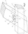
Figur 1- eine schematische Seitenansicht eines Dachfensters in Anfangsöffnungsschwingstellung,
Figur 2- eine Detailansicht eines Führungselements, daß sich entlang einer Führungsbahn auf der Oberfläche eines Blendrahmens des Wohndachfensters bewegt,
Figur 3- eine der
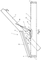
Figur 2 entsprechende Darstellung, jedoch mit einem andersartig gestalteten Führungselement, Figur 4- eine schematische Seitenansicht eines weiteren Ausführungsbeispiels eines Dachfensters, ebenfalls in Anfangsschwingöffnungsstellung,
Figur 5- eine der
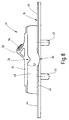
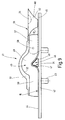
Figur 4 entsprechende Darstellung, jedoch bei weiter geöffnetem Fenster, Figur 6- eine Höhenumlenkung, die als Aufsatzteil ausgebildet ist und zur Aufnahme des Führungselements dient,
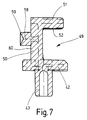
Figur 7- eine Schnittansicht durch die
Höhenumlenkung der Figur 6, Figur 8- eine Höhenumlenkung nach einem anderen Ausführungsbeispiel und
Figur 9- ein weiteres Ausführungsbeispiel einer Höhenumlenkung.
- Figure 1
- 1 shows a schematic side view of a roof window in the initial opening swing position,
- Figure 2
- 1 shows a detailed view of a guide element that moves along a guide path on the surface of a frame of the roof window,
- Figure 3
- 2 shows a representation corresponding to FIG. 2, but with a differently designed guide element,
- Figure 4
- 2 shows a schematic side view of a further exemplary embodiment of a roof window, also in the initial swing opening position,
- Figure 5
- 4 shows a representation corresponding to FIG. 4, but with the window open further,
- Figure 6
- a height deflection, which is designed as an attachment part and serves to receive the guide element,
- Figure 7
- 6 shows a sectional view through the vertical deflection of FIG. 6,
- Figure 8
- a height deflection according to another embodiment and
- Figure 9
- another embodiment of a height deflection.
Die Figur 1 zeigt ein Wohndachfenster 1 in Seitenansicht,
das sich in geöffneter Anfangsschwingposition
befindet. Das Wohndachfenster 1 ist als
Klapp-/Schwing-Flügel-Dachfenster ausgebildet. Es
weist einen Blendrahmen 2 und einen Flügelrahmen 3
auf. Der für den Einbau in eine nicht dargestellte
Dachhaut vorgesehene Blendrahmen 2 besitzt zwei
parallel zueinander beabstandet verlaufende Längsholme
4 und zwei ebenfalls parallel zueinander beabstandet
verlaufende Querholme 5. Entsprechend ist
der Flügelrahmen 3 mit zwei parallel zueinander beabstandet
verlaufenden Längsholmen 6 sowie mit zwei
parallel zueinander beabstandet verlaufenden Querholmen
7 ausgestattet. Die beiden Längsholme 6 des
Flügelrahmens 3 weisen im Bereich ihrer Abschnitte
9 Hilfsrahmenprofile 10 auf, die am Blendrahmen 2
im Bereich des -in Einbauposition oberen- Querholms
5 um eine horizontale Achse 11 und am Flügelrahmen
3 um eine horizontale Achse 12 schwenkbar gelagert
sind.1 shows a
Befindet sich der Flügelrahmen 3 in Schließstellung,
so liegen die Hilfsrahmenprofile 10 parallel
auf den Längsholmen 6 auf und sind in dieser Position
fixiert. Wird der Betätigungsgriff 8 in
Klapposition verschwenkt, so bleiben die Hilfsrahmenprofile
10 auf den Längsholmen 6 parallel gekuppelt,
und es ist ein Verschwenken des Flügelrahmens
3 um die Achse 11 in Klappstellung möglich. Wird
der Betätigungsgriff 8 in Schwingstellung verbracht
und das Wohndachfenster 1 geöffnet, so wird die in
Figur 1 gezeichnete Stellung eingenommen, in der
eine Entkopplung der Hilfsrahmenprofile 10 von den
Längsholmen 6 des Flügelrahmens 3 vorliegt, so daß
die Hilfsrahmenprofile 10 gegenüber den Längsholmen
6 um die Achse 12 in eine Winkelposition verschwenken.
Gleichzeitig verschwenkt die Gesamtanordnung
um die Achse 11. Zur Realisierung dieser Bewegung
ist an den Außenseiten 13 der Längsholme 6 jeweils
ein Führungselement 14 befestigt, das sich entlang
einer Führungsbahn 15 abstützt. Die Achsen 11 und
12 sowie das Führungselement 14 liegen -wie aus der
Figur 1 ersichtlich- in der dort dargestellten
Schwingöffnungsstellung auf Eckpunkten eines gedachten
Dreiecks. Insofern weist das Führungselement
14 von der Achse 12 einen Abstand auf. Die
Achse 12 bildet eine Schwingachse, die es erlaubt,
den Flügelrahmen 3 maximal etwa um 180° zu drehen,
wodurch die Außenseite des Flügelrahmens 3 dem
Blendrahmen 2 zugekehrt wird, so daß zum Beispiel
die Außenseite der Verglasung vom Raum her gereinigt
werden kann. Ferner ermöglicht die
Schwingachse eine extrem weite Fensteröffnung, wie
sie aus der Figur 5 hervorgeht.If the
Aus der Figur 1 ist ersichtlich, daß an jedem
Längsholm 6 des Flügelrahmens 3, schwenkbeweglich
um eine horizontale Achse 16, eine Federvorrichtung
17 angeordnet ist, die jeweils eine Schwinghilfe 18
beim Öffnen des Wohndachfensters 1 bildet. Die Federvorrichtung
17 ist teleskopartig ausgebildet;
sie besitzt ein Gehäuse 19, in dem sich eine nicht
dargestellte Schraubendruckfeder befindet, die mit
einer axial verlagerbaren Betätigungsstange 20 zusammenwirkt.
Anstelle der Schraubendruckfeder oder
zusätzlich zu dieser kann jedoch auch eine Gasfüllung
im Gehäuse 19 enthalten sein, das heißt, die
Federvorrichtung 17 ist als Gasdruckfeder ausgebildet.
Am zur Betätigungsstange 20 gegenüberliegenden
Ende des Gehäuses 19 ist eine fest stehende Stützstange
21 befestigt, die mit einer am Blendrahmen 2
angeordneten Abstützaufnahme 22 in bestimmten
Schwenkwinkelbereichen des Flügelrahmens 3 zusammenwirkt.
Das dem Gehäuse 19 abgewandte Ende der
Betätigungsstange 20 weist einen Betätigungsstangenkopf
23 auf, der um die Achse 16 schwenkbar an
dem Flügelrahmen 3 gelagert ist. Vorzugsweise ist
der Schwenkwinkel durch geeignete, nicht dargestellte
Anschlagmittel innerhalb eines bestimmten
Bereichs begrenzt, um zu verhindern, daß bei weit
geöffnetem Fenster die Federvorrichtung 17 in eine
Drehposition gelangt, in der sie die Sicht seitlich
aus dem Fenster behindern könnte. Das Ende 24 der
Stützstange 21 bildet ein freies Ende der Federvorrichtung
17. Dies bedeutet, daß es ab Erreichen einer
bestimmten Öffnungsstellung des Fensters von
der Abstützaufnahme 22 abheben kann, wie dies aus
der Figur 5 hervorgeht. Die Abstützaufnahme 22
weist ein Gegenlager 26 in Form einer Aufnahmevertiefung
27 auf, in die das freie Ende der Federvorrichtung
17 eintreten kann. Auf diese Art und Weise
stützt sich die Federvorrichtung 17 einerseits am
Blendrahmen 2 und andererseits am Flügelrahmen 3
ab, so daß -im Anfangs-Schwingöffnungsbereich- das
Fenster eine Öffnungshilfe erhält. Wird das Wohndachfenster
1 gegenüber der Stellung der Figur 1
weiter geöffnet, so verlagert sich dabei das Führungselement
14 in Richtung des in der Figur 1 eingezeichneten
Pfeils 28, das heißt, es durchläuft
dabei ein entsprechendes Teilstück der Führungsbahn
15. Die Führungsbahn 15 ist als dreiseitig geschlossener
Höhenumlenkungskanal 29 ausgebildet,
der sich an dem jeweiligen Längsholm 4 des Blendrahmens
2 befindet. In bezug zur Ebene 30 der Oberseite
31 des Blendrahmens 2, insbesondere hinsichtlich
dessen Längsholmen 4, weist die Führungsbahn
15 unterschiedliche Höhenniveaus auf, die daraus
resultieren, daß zwischen den beiden Endbereichen
32 und 33 des Führungskanals 15 eine Höhenumlenkung
34 liegt, das heißt, die Führungsbahn 15 weist von
der Oberseite 31 über ihre Länge nicht überall den
gleichen Abstand auf, sondern zwischen den Endbereichen
32 und 33 zumindest einen Abschnitt, der
der Oberseite 31 einen geringeren oder einen größeren
Abstand aufweist, so daß die bereits erwähnte
Höhenumlenkung 34 gebildet wird. Dies hat zur
Folge, daß bei einer Öffnungsbewegung oder aber
auch Schließbewegung des Flügelrahmens 3 das Führungselement
4 die Höhenumlenkung 34 überwinden
muß, was einen zusätzlichen Kraftaufwand erfordert,
der von dem Benutzer am Betätigungsgriff 8 aufzubringen
ist. Dementsprechend erfolgt eine Fensterflügelfixierung,
wenn das Führungselement 14 gegen
die entsprechende Flanke der Höhenumlenkung 34 anläuft.
Eine selbsttätige Verstellung des jeweiligen
Öffnungswinkels des Flügelrahmens 3 wird dadurch
verhindert. Selbstverständlich ist es möglich, über
die Länge der Führungsbahn 15 mehrere Höhenumlenkungen
34 vorzusehen, so daß der Flügelrahmen 3 in
mehreren Winkelpositionen fixiert werden kann.From Figure 1 it can be seen that on each
Das Führungselement 14 ist in Figur 2 im Detail
dargestellt. Es besteht aus einem seitlich aus dem
Längsholm 6 herausragenden zylindrischen Zapfen 35
mit kreisförmigen Querschnitt. Es ist erkennbar,
daß der Zapfen 35 auf der eben ausgebildeten Oberseite
31 des Längsholms 4 aufliegt. Demzufolge befindet
sich beim Ausführungsbeispiel der Figur 2
die Führungsbahn 15 somit auf der Oberseite 31 des
Blendrahmens 2.The
Gemäß Figur 3 kann nach einem anderen Ausführungsbeispiel
der Erfindung vorgesehen sein, daß das
Führungselement 14 einen seitlich aus dem Längsholm
6 des Flügelsrahmens 3 herausragenden Bolzen 36
aufweist, auf den -drehbeweglich- ein Gleitstein 37
angeordnet ist. Der Gleitstein 37 liegt mit einer
Stützfläche 38 auf der ebenen Oberseite 31, die die
Führungsbahn 15 bildet, auf. Der Gleitstein 37 besitzt
auf einander gegenüberliegenden Seiten jeweils
dachartig zulaufende Verlagerungsschrägen 39,
40, die mit der Höhenumlenkung zusammenwirken, wie
nachstehend noch näher beschrieben wird.According to Figure 3 can be according to another embodiment
the invention provided that the
Die Figur 4 zeigt eine weitere Ausführungsform eines
Wohndachfensters 1, die sich gegenüber der Ausführungsform
der Figur 1 dadurch unterscheidet, daß
anstelle eines Zapfens 35 ein Gleitstein 37 vorgesehen
ist, der sich entlang der ebenen Oberseite 31
des Blendrahmens 2 entlang der Führungsbahn 15 bewegt,
wenn der Flügelrahmen 3 verschwenkt wird.
Zwischen den Endbereichen 32, 33 der Führungsbahn
15 liegt eine Höhenumlenkung 34, die als Aufsatzteil
41 ausgebildet ist, das heißt sie wird dem
Blendrahmen 2 zugeordnet und dort beispielsweise
mittels Schrauben gehalten. Das Aufsatzteil 41 ist
derart ausgebildet, daß es eine Abstützaufnahme 22
für die Stützstange 21 der Federvorrichtung 17 aufweist.
Auf die konstruktive Ausgestaltung des Aufsatzteils
41 wird nachstehend näher eingegangen.FIG. 4 shows a further embodiment of a
Die Figur 5 zeigt das Ausführungsbeispiel der Figur
4, wobei sich der Flügelrahmen 3 jedoch in einer
weiter geöffneten Stellung befindet. Es ist erkennbar,
daß durch das weitere Öffnen die Federvorrichtung
17 nicht mehr mit dem Blendrahmen 2 zusammenwirkt,
das heißt sie wirkt keine Kraft mehr auf den
Flügelrahmen 3 aus. Der das Führungselement 14 bildende
Gleitstein 37 hat sich von seiner linksseitig
des Aufsatzteils 41 liegenden Position auf die
rechte Seite von dem Aufsatzteil 41 bewegt, das
heißt er hat das Aufsatzteil 41 durchlaufen. Hierauf
wird nachstehend ebenfalls näher eingegangen.Figure 5 shows the embodiment of the figure
4, the
Die Figur 6 zeigt das Aufsatzteil 41, das eine
Grundplatte 42 aufweist, die an ihrer Unterseite
Positionierzapfen 43 besitzt. Im am Blendrahmen 2
montierten Zustand greifen sowohl die Grundplatte
42 als auch die Positionierzapfen 43 in den Blendrahmen
2 derart ein, daß die Oberseite 31 des
Blendrahmens 2 mit den eben verlaufenden Bereichen
44 und 45 der Oberseite der Grundplatte 2 fluchten.
Die Bereiche 44 und 45 bilden somit Abschnitte der
Führungsbahn 15. Zwischen den Bereichen 44 und 45
liegt eine Höhenumlenkung 34, die von einer Erhebung
46 gebildet wird und ebenfalls der Führungsbahn
15 angehört. Die Erhebung ist asymmetrisch
ausgebildet, das heißt sie besitzt eine dem Bereich
44 zugeordnete Flanke 47, die steiler ist als die
dem Bereich 45 zugeordnete Flanke 48. Die Führungsbahn
15 ist im Bereich der Erhebung 46 als Höhenumlenkungskanal
49 ausgebildet, das heißt von der
Grundplatte 42 geht -gemäß Figur 7- eine Seitenwand
50 aus, von der ein Schenkel 51 ausgeht, wobei ein
Teil der Grundplatte 42, die Seitenwand 50 und der
Schenkel 51 ein U-Profil bilden, in dessen Inneren
der Höhenumlenkungskanal 49 ausgebildet ist. Die
Innenseite 52 des Schenkels 51 ist der Höhenkontur
der Führungsbahn 15 im Bereich der Erhebung 46 entsprechend
angepaßt, so daß eine exakte Führung des
Führungselements 14 innerhalb des Höhenumlenkungskanals
49 erfolgt. Da der Gleitstein 37 beim Einfahren
in den Höhenumlenkungskanal 49 gegen die
Flanke 47 der Erhebung 46 tritt, erfolgt eine Fixierung
der entsprechenden Winkelstellung des Flügelrahmens
3. Um den Flügelrahmen 3 weiter zu öffnen,
ist es erforderlich, eine entsprechend große
Verschwenkungskraft aufzubringen, das heißt der Benutzer
muß eine entsprechende Kraft am Betätigungsgriff
8 aufbringen. Hierdurch verschwenkt der
Gleitstein 37, da die Verlagerungsschräge 39 gegen
die Flanke 47 tritt. Im Zuge der weiteren Öffnungsbewegung
gleitet der Gleitstein weiter durch den
Höhenumlenkungskanal 49 und schwenkt dann in die
entgegengesetzte Richtung zurück, da die Verlagerungsschräge
40 gegen die gekrümmte Innenseite 52
des Schenkels 51 tritt. Wird das Fenster wieder geschlossen,
so erfolgt eine entsprechend entgegengesetzte
Bewegung des Gleitsteins 37, wobei er auf
die Flanke 48 der Erhebung 46 auftrifft und dort
die Fensterstellung fixiert. Durch entsprechenden
Kraftaufwand kann diese Fixierung wieder aufgehoben
werden, wobei dies eine geringere Kraft erfordert
als beim Überwinden der Flanke 47, da die Flanke 48
flacher verläuft.FIG. 6 shows the
Es ist erkennbar, daß auf der Außenseite 53 des
Schenkels 51 eine Abstützaufnahme 54 für die Federvorrichtung
17 ausgebildet ist.It can be seen that on the outside 53 of the
Leg 51 a
Die Figur 8 zeigt ein weiteres Ausführungsbeispiel
eines mit Höhenumlenkung 34 versehenen Aufsatzteils
41, das sich gegenüber dem Ausführungsbeispiel der
Figur 6 im wesentlichen dadurch unterscheidet, daß
keine Erhebung vorgesehen ist, sondern eine Vertiefung
55, das heißt beim Passieren des Höhenumlenkungskanals
49 tritt das Führungselement 14 in die
Vertiefung 55 ein und fixiert auf diese Art und
Weise die Stellung des Flügelrahmens 3.Figure 8 shows a further embodiment
a top section provided with a
Die Figur 9 zeigt ein Ausführungsbeispiel eines mit
Höhenumlenkung 34 versehenen Aufsatzteils 41, das
dem Ausführungsbeispiel der Figur 6 entspricht, jedoch
zusätzlich ein klappenartig verschwenkbares
Passierelement 56 aufweist. Das Passierelement 56
weist einen seitlich zum Höhenumlenkungskanal 49
gelegenen Lagerschenkel 57 auf, der um eine Achse
58 drehbar auf einem Zapfen 59 auf der Rückseite 60
der Seitenwand 50 gelagert ist (der Zapfen 59 geht
aus der Figur 7 hervor). In den Höhenumlenkungskanal
49 reicht ein am Lagerschenkel 57 angeordnetes
Steuerelement 60 hinein, das beidseitig Auflaufschrägen
61 und 62 besitzt, um das Führungselement
14 passieren zu lassen, das heißt: trifft das Führungselement
14 auf die Auflaufschräge 61 oder 62,
so verschwenkt das Passierelement 56 um die Achse
58 nach oben, so daß das Führungselement 14 passieren
kann. Da auf der Oberseite des Steuerelements
60 die Abstützaufnahme 54 für die Federvorrichtung
17 angeordnet ist, kann das Führungselement 14
selbst dann das Aufsatzteil 41 passieren, wenn sich
die Federvorrichtung 17 noch in der Abstützaufnahme
54 abstützt.Figure 9 shows an embodiment of a
Claims (12)
Priority Applications (1)
| Application Number | Priority Date | Filing Date | Title |
|---|---|---|---|
| DK99112507T DK0972885T3 (en) | 1998-07-17 | 1999-07-01 | Svingeflöjs-skylight |
Applications Claiming Priority (2)
| Application Number | Priority Date | Filing Date | Title |
|---|---|---|---|
| DE19832262 | 1998-07-17 | ||
| DE19832262A DE19832262A1 (en) | 1998-07-17 | 1998-07-17 | Swing-wing skylight |
Publications (2)
| Publication Number | Publication Date |
|---|---|
| EP0972885A1 true EP0972885A1 (en) | 2000-01-19 |
| EP0972885B1 EP0972885B1 (en) | 2004-09-15 |
Family
ID=7874462
Family Applications (1)
| Application Number | Title | Priority Date | Filing Date |
|---|---|---|---|
| EP99112507A Expired - Lifetime EP0972885B1 (en) | 1998-07-17 | 1999-07-01 | Tilting roof window |
Country Status (4)
| Country | Link |
|---|---|
| EP (1) | EP0972885B1 (en) |
| AT (1) | ATE276411T1 (en) |
| DE (2) | DE19832262A1 (en) |
| DK (1) | DK0972885T3 (en) |
Cited By (7)
| Publication number | Priority date | Publication date | Assignee | Title |
|---|---|---|---|---|
| EP1355017A2 (en) * | 2002-04-17 | 2003-10-22 | Roto Frank Ag | Roof window with a pivoting window part |
| EP1703038A3 (en) * | 2005-02-23 | 2008-06-11 | Accuride International Limited | Roof vent |
| EP2280143A2 (en) | 2003-08-20 | 2011-02-02 | VKR Holding A/S | An improved pivot window with at least one auxiliary opening device |
| CN103590543A (en) * | 2013-11-01 | 2014-02-19 | 安徽工贸职业技术学院 | Open-type flexible roof window |
| CN103590542A (en) * | 2013-11-01 | 2014-02-19 | 安徽工贸职业技术学院 | Roof window structure |
| EP2821575A2 (en) | 2003-08-20 | 2015-01-07 | VKR Holding A/S | An improved pivot window with at least one auxiliary opening device and check means |
| EP2525013A3 (en) * | 2011-05-14 | 2015-08-12 | Roto Frank AG | Holding device for a residential skylight and residential skylight with holding device |
Families Citing this family (1)
| Publication number | Priority date | Publication date | Assignee | Title |
|---|---|---|---|---|
| CN1975085B (en) * | 2006-10-13 | 2010-09-15 | 江苏大学 | Single-freedom planar six-rod window-opening mechanism |
Citations (5)
| Publication number | Priority date | Publication date | Assignee | Title |
|---|---|---|---|---|
| US2080868A (en) * | 1935-11-25 | 1937-05-18 | Mayes Jess | Window sash |
| US2086043A (en) * | 1936-08-17 | 1937-07-06 | Vento Steel Sash Co Inc | Window construction |
| US2648878A (en) * | 1947-01-06 | 1953-08-18 | Albano Edmond | Completely reversible window |
| US4055024A (en) * | 1975-05-03 | 1977-10-25 | Wilh. Frank Gmbh | Roof window arrangement |
| EP0846815A2 (en) * | 1996-12-04 | 1998-06-10 | ROTO FRANK Aktiengesellschaft | Roof window, in particular tilting window |
Family Cites Families (2)
| Publication number | Priority date | Publication date | Assignee | Title |
|---|---|---|---|---|
| DE2631453C2 (en) * | 1976-07-13 | 1989-08-31 | Hans 7031 Steinenbronn Vollmer | Fitting for roof windows |
| DE19717070C1 (en) * | 1997-04-23 | 1998-11-12 | Roto Frank Ag | Skylights, in particular swing-wing skylights |
-
1998
- 1998-07-17 DE DE19832262A patent/DE19832262A1/en not_active Withdrawn
-
1999
- 1999-07-01 DK DK99112507T patent/DK0972885T3/en active
- 1999-07-01 DE DE59910492T patent/DE59910492D1/en not_active Expired - Lifetime
- 1999-07-01 EP EP99112507A patent/EP0972885B1/en not_active Expired - Lifetime
- 1999-07-01 AT AT99112507T patent/ATE276411T1/en active
Patent Citations (5)
| Publication number | Priority date | Publication date | Assignee | Title |
|---|---|---|---|---|
| US2080868A (en) * | 1935-11-25 | 1937-05-18 | Mayes Jess | Window sash |
| US2086043A (en) * | 1936-08-17 | 1937-07-06 | Vento Steel Sash Co Inc | Window construction |
| US2648878A (en) * | 1947-01-06 | 1953-08-18 | Albano Edmond | Completely reversible window |
| US4055024A (en) * | 1975-05-03 | 1977-10-25 | Wilh. Frank Gmbh | Roof window arrangement |
| EP0846815A2 (en) * | 1996-12-04 | 1998-06-10 | ROTO FRANK Aktiengesellschaft | Roof window, in particular tilting window |
Cited By (10)
| Publication number | Priority date | Publication date | Assignee | Title |
|---|---|---|---|---|
| EP1355017A2 (en) * | 2002-04-17 | 2003-10-22 | Roto Frank Ag | Roof window with a pivoting window part |
| EP1355017A3 (en) * | 2002-04-17 | 2005-02-02 | Roto Frank Ag | Roof window with a pivoting window part |
| CZ304260B6 (en) * | 2002-04-17 | 2014-02-05 | Roto Frank Ag | Skylight in inclined roof, performed as a swinging skylight |
| EP2280143A2 (en) | 2003-08-20 | 2011-02-02 | VKR Holding A/S | An improved pivot window with at least one auxiliary opening device |
| EP2821575A2 (en) | 2003-08-20 | 2015-01-07 | VKR Holding A/S | An improved pivot window with at least one auxiliary opening device and check means |
| EP2821575A3 (en) * | 2003-08-20 | 2015-03-04 | VKR Holding A/S | An improved pivot window with at least one auxiliary opening device and check means |
| EP1703038A3 (en) * | 2005-02-23 | 2008-06-11 | Accuride International Limited | Roof vent |
| EP2525013A3 (en) * | 2011-05-14 | 2015-08-12 | Roto Frank AG | Holding device for a residential skylight and residential skylight with holding device |
| CN103590543A (en) * | 2013-11-01 | 2014-02-19 | 安徽工贸职业技术学院 | Open-type flexible roof window |
| CN103590542A (en) * | 2013-11-01 | 2014-02-19 | 安徽工贸职业技术学院 | Roof window structure |
Also Published As
| Publication number | Publication date |
|---|---|
| DE19832262A1 (en) | 2000-01-20 |
| EP0972885B1 (en) | 2004-09-15 |
| DE59910492D1 (en) | 2004-10-21 |
| DK0972885T3 (en) | 2004-12-06 |
| ATE276411T1 (en) | 2004-10-15 |
Similar Documents
| Publication | Publication Date | Title |
|---|---|---|
| EP0687787B1 (en) | Hinge device | |
| EP0679775B1 (en) | Tilting/oscillating roof window with counterbalance | |
| DE2648344A1 (en) | FITTINGS FOR SLIDING WINDOWS, SLIDING DOORS, ETC. | |
| EP0972885B1 (en) | Tilting roof window | |
| EP0201717B1 (en) | Fitting for a wing of a window, door or the like, which can at least be moved from one plane to another parallel plane | |
| EP1017920B1 (en) | Brace for pivotally mounting a wing of a window or door | |
| EP0438740A1 (en) | Fitting for a wing of a window, door or similar which at least pivots | |
| DE3222678C2 (en) | Tilt & Turn hardware | |
| EP3749822B1 (en) | Assisting fitting for a tiltable wing of a window or door | |
| EP0846815B1 (en) | Roof window, in particular tilting window | |
| EP0874102B1 (en) | Roof window, in particular tilting window | |
| EP0851085A1 (en) | Tilt- and turn fitting with a non-slidable corner support | |
| DE19600948C1 (en) | Equipment to balance weight of skylight window | |
| DE8103368U1 (en) | Tilt and turn window or door | |
| EP0874123B1 (en) | Fitting for supporting a window or door swinging wing | |
| DE2658463A1 (en) | Attic dwelling room hinged window - has two sets of hinges and sloping guide with holding stay | |
| DE4422213C2 (en) | turn-tilt fitting | |
| EP1581712B1 (en) | Mounting unit for a window or a door | |
| EP0874103A2 (en) | Tilting window for a pitched roof | |
| DE3911187A1 (en) | Lifting/tilting window | |
| DE1930485A1 (en) | Swivel sliding door, especially for road and rail vehicles | |
| DE19825071A1 (en) | Adjustment mechanism for window casement parallel with frame | |
| DE2631453A1 (en) | Hinge fitting for roof window - has single connection for opening and moving into cleaning position | |
| CH655970A5 (en) | Dormer window | |
| DE1213290B (en) | Fitting for window sash |
Legal Events
| Date | Code | Title | Description |
|---|---|---|---|
| PUAI | Public reference made under article 153(3) epc to a published international application that has entered the european phase |
Free format text: ORIGINAL CODE: 0009012 |
|
| AK | Designated contracting states |
Kind code of ref document: A1 Designated state(s): AT CH DE DK FR GB LI |
|
| AX | Request for extension of the european patent |
Free format text: AL;LT;LV;MK;RO;SI |
|
| 17P | Request for examination filed |
Effective date: 20000704 |
|
| AKX | Designation fees paid |
Free format text: AT CH DE DK FR GB LI |
|
| 17Q | First examination report despatched |
Effective date: 20030416 |
|
| GRAP | Despatch of communication of intention to grant a patent |
Free format text: ORIGINAL CODE: EPIDOSNIGR1 |
|
| GRAS | Grant fee paid |
Free format text: ORIGINAL CODE: EPIDOSNIGR3 |
|
| GRAA | (expected) grant |
Free format text: ORIGINAL CODE: 0009210 |
|
| AK | Designated contracting states |
Kind code of ref document: B1 Designated state(s): AT CH DE DK FR GB LI |
|
| REG | Reference to a national code |
Ref country code: GB Ref legal event code: FG4D Free format text: NOT ENGLISH Ref country code: CH Ref legal event code: EP |
|
| REF | Corresponds to: |
Ref document number: 59910492 Country of ref document: DE Date of ref document: 20041021 Kind code of ref document: P |
|
| REG | Reference to a national code |
Ref country code: CH Ref legal event code: NV Representative=s name: E. BLUM & CO. PATENTANWAELTE |
|
| REG | Reference to a national code |
Ref country code: DK Ref legal event code: T3 |
|
| GBT | Gb: translation of ep patent filed (gb section 77(6)(a)/1977) |
Effective date: 20050110 |
|
| ET | Fr: translation filed | ||
| PLBE | No opposition filed within time limit |
Free format text: ORIGINAL CODE: 0009261 |
|
| STAA | Information on the status of an ep patent application or granted ep patent |
Free format text: STATUS: NO OPPOSITION FILED WITHIN TIME LIMIT |
|
| 26N | No opposition filed |
Effective date: 20050616 |
|
| REG | Reference to a national code |
Ref country code: CH Ref legal event code: PFA Owner name: ROTO FRANK AG Free format text: ROTO FRANK AG#STUTTGARTER STRASSE 145-149#70771 LEINFELDEN-ECHTERDINGEN (DE) -TRANSFER TO- ROTO FRANK AG#STUTTGARTER STRASSE 145-149#70771 LEINFELDEN-ECHTERDINGEN (DE) |
|
| PGFP | Annual fee paid to national office [announced via postgrant information from national office to epo] |
Ref country code: GB Payment date: 20110620 Year of fee payment: 13 |
|
| PGFP | Annual fee paid to national office [announced via postgrant information from national office to epo] |
Ref country code: DK Payment date: 20110704 Year of fee payment: 13 |
|
| GBPC | Gb: european patent ceased through non-payment of renewal fee |
Effective date: 20120701 |
|
| PG25 | Lapsed in a contracting state [announced via postgrant information from national office to epo] |
Ref country code: GB Free format text: LAPSE BECAUSE OF NON-PAYMENT OF DUE FEES Effective date: 20120701 |
|
| REG | Reference to a national code |
Ref country code: DK Ref legal event code: EBP Effective date: 20130731 |
|
| PG25 | Lapsed in a contracting state [announced via postgrant information from national office to epo] |
Ref country code: DK Free format text: LAPSE BECAUSE OF NON-PAYMENT OF DUE FEES Effective date: 20130731 |
|
| PGFP | Annual fee paid to national office [announced via postgrant information from national office to epo] |
Ref country code: CH Payment date: 20140722 Year of fee payment: 16 |
|
| PGFP | Annual fee paid to national office [announced via postgrant information from national office to epo] |
Ref country code: AT Payment date: 20140620 Year of fee payment: 16 |
|
| REG | Reference to a national code |
Ref country code: CH Ref legal event code: PL |
|
| REG | Reference to a national code |
Ref country code: AT Ref legal event code: MM01 Ref document number: 276411 Country of ref document: AT Kind code of ref document: T Effective date: 20150701 |
|
| PG25 | Lapsed in a contracting state [announced via postgrant information from national office to epo] |
Ref country code: LI Free format text: LAPSE BECAUSE OF NON-PAYMENT OF DUE FEES Effective date: 20150731 Ref country code: CH Free format text: LAPSE BECAUSE OF NON-PAYMENT OF DUE FEES Effective date: 20150731 |
|
| PG25 | Lapsed in a contracting state [announced via postgrant information from national office to epo] |
Ref country code: AT Free format text: LAPSE BECAUSE OF NON-PAYMENT OF DUE FEES Effective date: 20150701 |
|
| REG | Reference to a national code |
Ref country code: FR Ref legal event code: PLFP Year of fee payment: 18 |
|
| PGFP | Annual fee paid to national office [announced via postgrant information from national office to epo] |
Ref country code: DE Payment date: 20160721 Year of fee payment: 18 |
|
| PGFP | Annual fee paid to national office [announced via postgrant information from national office to epo] |
Ref country code: FR Payment date: 20160722 Year of fee payment: 18 |
|
| REG | Reference to a national code |
Ref country code: DE Ref legal event code: R119 Ref document number: 59910492 Country of ref document: DE |
|
| REG | Reference to a national code |
Ref country code: FR Ref legal event code: ST Effective date: 20180330 |
|
| PG25 | Lapsed in a contracting state [announced via postgrant information from national office to epo] |
Ref country code: DE Free format text: LAPSE BECAUSE OF NON-PAYMENT OF DUE FEES Effective date: 20180201 |
|
| PG25 | Lapsed in a contracting state [announced via postgrant information from national office to epo] |
Ref country code: FR Free format text: LAPSE BECAUSE OF NON-PAYMENT OF DUE FEES Effective date: 20170731 |