EP0972660A1 - Sensor assembly at a wheel suspension for a vehicle - Google Patents
Sensor assembly at a wheel suspension for a vehicle Download PDFInfo
- Publication number
- EP0972660A1 EP0972660A1 EP99111629A EP99111629A EP0972660A1 EP 0972660 A1 EP0972660 A1 EP 0972660A1 EP 99111629 A EP99111629 A EP 99111629A EP 99111629 A EP99111629 A EP 99111629A EP 0972660 A1 EP0972660 A1 EP 0972660A1
- Authority
- EP
- European Patent Office
- Prior art keywords
- sensor
- vehicle body
- swivel arm
- fastening element
- arrangement according
- Prior art date
- Legal status (The legal status is an assumption and is not a legal conclusion. Google has not performed a legal analysis and makes no representation as to the accuracy of the status listed.)
- Granted
Links
Images

Classifications
-
- B—PERFORMING OPERATIONS; TRANSPORTING
- B60—VEHICLES IN GENERAL
- B60G—VEHICLE SUSPENSION ARRANGEMENTS
- B60G17/00—Resilient suspensions having means for adjusting the spring or vibration-damper characteristics, for regulating the distance between a supporting surface and a sprung part of vehicle or for locking suspension during use to meet varying vehicular or surface conditions, e.g. due to speed or load
- B60G17/015—Resilient suspensions having means for adjusting the spring or vibration-damper characteristics, for regulating the distance between a supporting surface and a sprung part of vehicle or for locking suspension during use to meet varying vehicular or surface conditions, e.g. due to speed or load the regulating means comprising electric or electronic elements
- B60G17/019—Resilient suspensions having means for adjusting the spring or vibration-damper characteristics, for regulating the distance between a supporting surface and a sprung part of vehicle or for locking suspension during use to meet varying vehicular or surface conditions, e.g. due to speed or load the regulating means comprising electric or electronic elements characterised by the type of sensor or the arrangement thereof
- B60G17/01933—Velocity, e.g. relative velocity-displacement sensors
-
- B—PERFORMING OPERATIONS; TRANSPORTING
- B60—VEHICLES IN GENERAL
- B60G—VEHICLE SUSPENSION ARRANGEMENTS
- B60G2200/00—Indexing codes relating to suspension types
- B60G2200/10—Independent suspensions
- B60G2200/14—Independent suspensions with lateral arms
- B60G2200/142—Independent suspensions with lateral arms with a single lateral arm, e.g. MacPherson type
-
- B—PERFORMING OPERATIONS; TRANSPORTING
- B60—VEHICLES IN GENERAL
- B60G—VEHICLE SUSPENSION ARRANGEMENTS
- B60G2204/00—Indexing codes related to suspensions per se or to auxiliary parts
- B60G2204/10—Mounting of suspension elements
- B60G2204/11—Mounting of sensors thereon
-
- B—PERFORMING OPERATIONS; TRANSPORTING
- B60—VEHICLES IN GENERAL
- B60G—VEHICLE SUSPENSION ARRANGEMENTS
- B60G2204/00—Indexing codes related to suspensions per se or to auxiliary parts
- B60G2204/10—Mounting of suspension elements
- B60G2204/11—Mounting of sensors thereon
- B60G2204/116—Sensors coupled to the suspension arm
-
- B—PERFORMING OPERATIONS; TRANSPORTING
- B60—VEHICLES IN GENERAL
- B60G—VEHICLE SUSPENSION ARRANGEMENTS
- B60G2204/00—Indexing codes related to suspensions per se or to auxiliary parts
- B60G2204/10—Mounting of suspension elements
- B60G2204/14—Mounting of suspension arms
- B60G2204/143—Mounting of suspension arms on the vehicle body or chassis
-
- B—PERFORMING OPERATIONS; TRANSPORTING
- B60—VEHICLES IN GENERAL
- B60G—VEHICLE SUSPENSION ARRANGEMENTS
- B60G2204/00—Indexing codes related to suspensions per se or to auxiliary parts
- B60G2204/40—Auxiliary suspension parts; Adjustment of suspensions
- B60G2204/422—Links for mounting suspension elements
-
- B—PERFORMING OPERATIONS; TRANSPORTING
- B60—VEHICLES IN GENERAL
- B60G—VEHICLE SUSPENSION ARRANGEMENTS
- B60G2204/00—Indexing codes related to suspensions per se or to auxiliary parts
- B60G2204/40—Auxiliary suspension parts; Adjustment of suspensions
- B60G2204/43—Fittings, brackets or knuckles
-
- B—PERFORMING OPERATIONS; TRANSPORTING
- B60—VEHICLES IN GENERAL
- B60G—VEHICLE SUSPENSION ARRANGEMENTS
- B60G2400/00—Indexing codes relating to detected, measured or calculated conditions or factors
- B60G2400/05—Attitude
- B60G2400/051—Angle
- B60G2400/0516—Angular position of a suspension element
- B60G2400/05162—Angular position of a suspension element the element being a suspension arm
-
- B—PERFORMING OPERATIONS; TRANSPORTING
- B60—VEHICLES IN GENERAL
- B60G—VEHICLE SUSPENSION ARRANGEMENTS
- B60G2400/00—Indexing codes relating to detected, measured or calculated conditions or factors
- B60G2400/25—Stroke; Height; Displacement
- B60G2400/252—Stroke; Height; Displacement vertical
-
- B—PERFORMING OPERATIONS; TRANSPORTING
- B60—VEHICLES IN GENERAL
- B60G—VEHICLE SUSPENSION ARRANGEMENTS
- B60G2401/00—Indexing codes relating to the type of sensors based on the principle of their operation
-
- G—PHYSICS
- G01—MEASURING; TESTING
- G01D—MEASURING NOT SPECIALLY ADAPTED FOR A SPECIFIC VARIABLE; ARRANGEMENTS FOR MEASURING TWO OR MORE VARIABLES NOT COVERED IN A SINGLE OTHER SUBCLASS; TARIFF METERING APPARATUS; MEASURING OR TESTING NOT OTHERWISE PROVIDED FOR
- G01D2205/00—Indexing scheme relating to details of means for transferring or converting the output of a sensing member
- G01D2205/10—Detecting linear movement
- G01D2205/14—Detecting linear movement by converting the linear movement into a rotary movement
-
- Y—GENERAL TAGGING OF NEW TECHNOLOGICAL DEVELOPMENTS; GENERAL TAGGING OF CROSS-SECTIONAL TECHNOLOGIES SPANNING OVER SEVERAL SECTIONS OF THE IPC; TECHNICAL SUBJECTS COVERED BY FORMER USPC CROSS-REFERENCE ART COLLECTIONS [XRACs] AND DIGESTS
- Y10—TECHNICAL SUBJECTS COVERED BY FORMER USPC
- Y10S—TECHNICAL SUBJECTS COVERED BY FORMER USPC CROSS-REFERENCE ART COLLECTIONS [XRACs] AND DIGESTS
- Y10S280/00—Land vehicles
- Y10S280/01—Load responsive, leveling of vehicle
Definitions
- the invention relates to a sensor arrangement on a wheel suspension for a vehicle with the features of the generic term of claim 1.
- a sensor arrangement known from DE 39 19 040 A1 The type mentioned is a swivel arm on a vehicle body pivoted and a sensor for detection the relative position between the swivel arm and the vehicle body fixed to the vehicle body.
- the sensor Around the relative position between the swivel arm and the vehicle body detect, the sensor is mechanically coupled to the swivel arm.
- a sensor arrangement is known from DE 44 29 856 C1, at the one axis of rotation of the sensor coaxial to a pivot axis the swivel arm is arranged around which the swivel arm Wheel suspension swiveling on the rebound and rebound Vehicle body is stored.
- tolerance compensation can be done electronically be carried out, with the respective electronics theoretically any sensor position specified as zero position can be.
- the structure of which is only the acquisition a limited measuring range in the form of deviations from a starting position, but has one of one
- the specified target installation position actually deviates from the actual installation position in practice a reduction in the measuring range or, if the sensor electronics enable such a calibration, reduced measuring accuracy.
- the present invention addresses the problem a sensor arrangement of the type mentioned with regard improve the implementation of tolerance compensation.
- the invention is based on the general idea for which Swivel arm and a common attachment point for the sensor to use on the vehicle body. This measure causes an essential relative measure between sensor and Swivel shaft only from the manufacturing tolerances of the swivel arm side fastener and the sensor side Fastener depends and not, as in the conventional Sensor arrangements, from the addition of the tolerances of the many individual components grouped together on the wheel suspension.
- the one between the mounting point and the sensor first straight line and one through the attachment point and the coupling point of the sensor to the Swing arm extending second straight line is included.
- tolerance compensation can thus be achieved for the relative position of the sensor at least regarding the distance between the sensor and the attachment point of the swivel arm are eliminated.
- the setting the required spatial arrangement from sensor to swivel arm can be relatively easy and with a fixed distance be performed relatively accurately.
- a tolerance compensation in this regard can preferably be done electronically without the measuring range of the sensor or its Measurement accuracy is significantly impaired.
- Sensor arrangement can the sensor-side fastener a sensor holder designed as a separate component to which the sensor is attached.
- a thing Component can be relatively inexpensive and highly accurate, for example are manufactured as a stamped part, so that the previously used Sensors can continue to be used without modification.
- the sensor holder has first fastening means, with which the sensor can be attached to the sensor holder, and second fasteners with which the sensor holder on the vehicle body together with the swivel arm side Fastener can be attached.
- first fastening means with which the sensor can be attached to the sensor holder
- second fasteners with which the sensor holder on the vehicle body together with the swivel arm side Fastener can be attached.
- Sensor arrangement can be the common attachment point of sensor-side fastening element and swivel arm side Fastener by one, the pivot axis of the Be pivot arm forming bearing pin. Moreover can then the swivel arm-side fastener through the Bearing pin pivotally attached to the vehicle body be, then the sensor-side fastener Bore, especially a fitting hole, for the bearing pin contains. This measure enables automatic assembly of sensor-side and swivel arm-side fastening element be performed on the vehicle body, with the Bearing pin next to the swivel arm-side fastening element at the same time the sensor-side listed or attached to it Fastener attached to the vehicle body becomes.
- Sensor arrangement can be provided to automatically find a given relative position the sensor-side fastening element with respect to the vehicle body serve.
- Such positioning is special feasible by machine.
- the relative position of the sensor depends on the Swivel arm also from the manufacturing and assembly tolerances of the individual parts of the wheel suspension.
- this has dependency in comparison with the relative position specified according to the invention between the sensor and the one with the swivel arm common attachment point on the vehicle body a significantly smaller influence on the adjustment the initial relative position between the swivel arm and the vehicle body, so that only a small tolerance compensation necessary is.
- This can be carried out electronically without the measuring range and / or the measuring accuracy of the sensor be noticeably affected.
- FIGS. 1 and 2 is the sensor arrangement according to the invention provided on a wheel suspension 1, with a not shown wheel of an otherwise not shown Vehicle is attached to the body 2.
- a bearing bracket 4 is formed on the vehicle body 2, on which the wishbone 3 is pivotable about a pivot axis 5 is stored.
- the pivotable attachment of the wishbone 3 to the vehicle body 2 or at their position console 4 is with the help a bearing bolt 6 designed as a fastening screw manufactured, which penetrates the bearing bracket 4 and with a Screwed pivot bearing of the wishbone 3, not shown is.
- the aforementioned swivel bearing is in one eye 7 of the wishbone 3 arranged and for clarity not shown.
- the bearing pin 6 penetrates the bearing bracket 4 in one for it provided, but not visible in FIGS. 1 and 2 Opening through which the relative position of the pivot axis 5 with respect the vehicle body 2 is set.
- To the in the frame of the assembly of the suspension add up Compensate for manufacturing and assembly tolerances of the individual components, becomes the aforementioned opening for the bearing pin 6 on the vehicle body, which is otherwise largely completed 2 retrofitted.
- Wishbone 3 becomes a sensor holder with the help of the bearing pin 6 8 attached to the vehicle body 2.
- the sensor holder 8 according to Kind of a washer on the pivot arm of the wishbone 3 opposite side of the bearing bracket 4 between the head of the bearing pin 6 and the bearing bracket 4 clamped.
- the bearing pin 6 or the one in the bearing bracket 4 provided opening thus forms for the wishbone 3 and the sensor holder 8 a common attachment point on the Vehicle body 2.
- the sensor 9 has a pivot lever 10 which supported at one end on a pivot lever axis 11 on the sensor 9 and is articulated at the other end with a control rod 12 connected is.
- the control rod 12 is in turn on her from Swivel lever 10 remote end at an articulation point 13 articulated connected to the wishbone 3. That way the sensor 9 is mechanically coupled to the wishbone 3. Swivel movements of the control arm 3 about its swivel axis 5 are transmitted from the control rod 12 to the pivot lever 10 and thus detected by the sensor 9.
- the relative position of the control arm 3 and thus the vehicle wheel coupled to it relative to the vehicle body be detected and for example in the form signal values generated by the sensor 9 to a level control device to get redirected.
- the pivot axis 5 of the wishbone 3 and preferably parallel pivot arm axis 11 on sensor 9 have a defined distance from each other.
- the wishbone 3 On the other hand must be in the presence of a reference position or relative starting position the wishbone 3 a defined output deflection or the starting position for the pivot lever 10 is maintained become.
- the aforementioned angle can thereby be set be that the sensor holder 8 in a certain Relative position with respect to the vehicle body 2 attached to this becomes.
- positioning means 14 and 15 intended.
- the tongue 14 extends from the sensor holder 8 approximately parallel to the pivot axis 5 in the direction on the bearing bracket 4. With the sensor holder 8 the tongue 14 penetrates the opening 15.
- the positioning means (Tongue 14 and opening 15) Play on. Because the positioning means (14 and 15) approximately vertically below the attachment point (Bearing pin 6) of the sensor holder 8 on the vehicle body 2 are arranged, the game mentioned essentially be formed only in the vertical direction. This vertical game is thereby in the illustrated embodiment achieved that the opening 15 as a vertically extending slot is trained.
- Deviations occurring between the desired target relative position the sensor holder 8 with respect to the wishbone 3 in its reference position, for example by a electronic calibration can be compensated for at due to the arrangement of the pivot lever 10 and control rod 12 hardly any impairment for the measuring range or the measuring accuracy of the sensor 9 results.
- the tongue 14 of the sensor holder 8 is on their free end converged.
- automated assembly of the sensor holder 8 simplified, since in the course of a machine-carried out Sliding the previous tip of the tongue 14 slightly can penetrate into the opening 15.
- slip-on movement causes the widening tongue 14 a Alignment of the sensor holder 8 relative to the vehicle body 2.
- openings 16 are provided, which for Serve positioning and attachment of the sensor 9.
- the sensor holder 8 has an opening 17 through which the Bearing pin 6 for attaching the sensor holder 8 to the Vehicle body 2 penetrates the sensor holder 8.
- the vehicle body 2 Since according to the invention a common attachment point of the bearing pin 6 for a sensor-side fastening element (Sensor holder 8) and a swivel arm-side fastening element (not shown pivot arm of the wishbone 3) the vehicle body 2 is provided, manufacturing and assembly tolerances of all other components of the Suspension 1 does not depend on the distance of the sensor 9 Impact pivot axis 5. A tolerance compensation is in this regard therefore no longer necessary.
- the Manufacture of the sensor holder 8 to pay particular attention to that on the one hand the relative position of the openings 16 for the Attachment of the sensor 9 with respect to the opening 17 for the Bearing pin 6 in a comparatively narrow tolerance range be formed.
- the openings mentioned 16 and 17 have centering properties, such as due to a tight fit, especially a press fit, can be realized.
- Sensor holder 8 can also correspond to a housing of sensor 9 be trained and e.g. the opening 17 for the bearing pin 6 included and with appropriate positioning be equipped.
Abstract
Description
Die Erfindung betrifft eine Sensoranordnung an einer Radaufhängung
für ein Fahrzeug mit den Merkmalen des Oberbegriffes
des Anspruches 1.The invention relates to a sensor arrangement on a wheel suspension
for a vehicle with the features of the generic term
of
Bei Fahrzeugen, insbesondere bei Kraftfahrzeugen wie Personenkraftwagen, Lastkraftwagen und Omnibussen, kann es für eine Vielzahl von fahrzeugseitigen Steuer- und Regeleinrichtungen erforderlich sein, bei einer Radaufhängung die Relativlage zwischen einer Fahrzeugkarosserie und einem daran schwenkbar gelagerten Schwenkarm zu kennen. Beispielsweise ermittelt die elektronische Steuerung einer Niveauregulierungseinrichtung mit Hilfe der Relativlage zwischen einem mit einem Rad gekoppelten Querlenker und der Fahrzeugkarosserie für jede Achse bzw. für jedes Rad den erforderlichen Regelbedarf, um ein vorbestimmtes Fahrzeugniveau einzustellen. Zur Erkennung wird ein Sensor verwendet, der üblicherweise die Abweichung des Schwenkarmes von einer Ausgangs-Relativlage detektiert.In vehicles, especially in motor vehicles such as passenger cars, Trucks and buses can do it for one Numerous on-board control and regulating devices be necessary with a wheel suspension the relative position between a vehicle body and a pivotable thereon to know the mounted swivel arm. For example, determined the electronic control of a level control device with the help of the relative position between one with a wheel coupled wishbones and the vehicle body for each Axis or for each wheel the required control order set a predetermined vehicle level. For recognition a sensor is used, which is usually the deviation of the swivel arm is detected from an initial relative position.
Bei einer aus der DE 39 19 040 A1 bekannten Sensoranordnung der eingangs genannten Art ist ein Schwenkarm an einer Fahrzeugkarosserie schwenkbar gelagert sowie ein Sensor zur Detektion der Relativlage zwischen Schwenkarm und Fahrzeugkarosserie ortsfest an der Fahrzeugkarosserie angebracht. Um die Relativlage zwischen Schwenkarm und Fahrzeugkarosserie zu erfassen, ist der Sensor mit dem Schwenkarm mechanisch gekoppelt.In a sensor arrangement known from DE 39 19 040 A1 The type mentioned is a swivel arm on a vehicle body pivoted and a sensor for detection the relative position between the swivel arm and the vehicle body fixed to the vehicle body. Around the relative position between the swivel arm and the vehicle body detect, the sensor is mechanically coupled to the swivel arm.
Aus der DE 44 29 856 C1 ist eine Sensoranordnung bekannt, bei der eine Drehachse des Sensors koaxial zu einer Schwenkachse des Schwenkarms angeordnet ist, um welche der Schwenkarm der Radaufhängung beim Ein- und Ausfedern verschwenkbar an der Fahrzeugkarosserie gelagert ist.A sensor arrangement is known from DE 44 29 856 C1, at the one axis of rotation of the sensor coaxial to a pivot axis the swivel arm is arranged around which the swivel arm Wheel suspension swiveling on the rebound and rebound Vehicle body is stored.
Im Rahmen der Montage eines Fahrzeuges werden die einzelnen Bestandteile einer Radaufhängung zusammengesetzt und montiert. Durch die Vielzahl der dabei zusammengefügten Einzelteile können sich deren Herstellungstoleranzen aufsummieren, so daß zur Definition einer Ausgangs-Relativlage zwischen dem Schwenkarm der Radaufhängung und der Fahrzeugkarosserie in jedem Fall ein Toleranzausgleich für den Sensor durchgeführt werden muß. Zur Durchführung eines derartigen Toleranzausgleiches stehen mehrere Vorgehensweisen zur Verfügung. Bei Sensoren, die mit einer längenverstellbaren Regelstange ausgestattet sind, kann der Toleranzausgleich mechanisch durch eine entsprechende Längeneinstellung dieser Regelstange durchgeführt werden. Damit jedoch ein derartiger Toleranzausgleich durchführbar ist, muß am Einbauort des Sensors ausreichend Platz zur manuellen Justage der Regelstange vorhanden sein, was jedoch nicht für jeden Fahrzeug-Typ gewährleistet werden kann.When assembling a vehicle, the individual Components of a wheel suspension assembled and assembled. Due to the large number of individual parts put together can add up their manufacturing tolerances, so that to define a starting relative position between the Swivel arm of the wheel suspension and the vehicle body in tolerance compensation for the sensor is carried out in every case must become. To carry out such tolerance compensation there are several procedures available. At Sensors equipped with a length-adjustable control rod tolerance compensation can be achieved mechanically a corresponding length setting of this control rod be performed. However, this means such tolerance compensation is feasible, must be sufficient at the installation site of the sensor There is space for manual adjustment of the control rod be, which however does not guarantee for every vehicle type can be.
Bei anderen Sensoren kann der Toleranzausgleich elektronisch durchgeführt werden, wobei der jeweiligen Elektronik theoretisch jede beliebige Sensorstellung als Nullstellung vorgegeben werden kann. Bei Sensoren, deren Aufbau nur die Erfassung eines begrenzten Meßbereiches in Form von Abweichungen von einer Ausgangsstellung ermöglicht, hat jedoch eine von einer vorgegebenen Soll-Einbaulage tatsächlich abweichende Ist-Einbaulage in der Praxis eine Verkleinerung des Meßbereiches oder, wenn die Sensorelektronik eine derartige Eichung ermöglicht, eine reduzierte Meßgenauigkeit zur Folge.With other sensors, tolerance compensation can be done electronically be carried out, with the respective electronics theoretically any sensor position specified as zero position can be. In the case of sensors, the structure of which is only the acquisition a limited measuring range in the form of deviations from a starting position, but has one of one The specified target installation position actually deviates from the actual installation position in practice a reduction in the measuring range or, if the sensor electronics enable such a calibration, reduced measuring accuracy.
Schließlich besteht - zumindest theoretisch - die Möglichkeit, den Sensor erst am fertigen Fahrzeug quasi als letzte Komponente zu montieren, um dann, während des Sensoreinbaus, diesen gleichzeitig in der gewünschten Ausrichtung zu justieren. Dies ist jedoch aufgrund der gegebenen Einbauverhältnisse regelmäßig nicht oder nur mit unverhältnismäßig großem Aufwand durchführbar.Finally - at least in theory - there is the possibility the sensor is almost the last on the finished vehicle Component in order to then, during sensor installation, to adjust it in the desired orientation at the same time. However, this is due to the given installation conditions regularly not or only with a disproportionately large amount Effort feasible.
Die vorliegende Erfindung beschäftigt sich mit dem Problem, eine Sensoranordnung der eingangs genannten Art hinsichtlich der Durchführung eines Toleranzausgleiches zu verbessern.The present invention addresses the problem a sensor arrangement of the type mentioned with regard improve the implementation of tolerance compensation.
Dieses Problem wird erfindungsgemäß durch eine Sensoranordnung
mit den Merkmalen des Anspruches 1 gelöst.According to the invention, this problem is solved by a sensor arrangement
solved with the features of
Die Erfindung beruht auf dem allgemeinen Gedanken, für den Schwenkarm und für den Sensor einen gemeinsamen Befestigungspunkt an der Fahrzeugkarosserie zu verwenden. Diese Maßnahme bewirkt, daß ein wesentliches Relativmaß zwischen Sensor und Schwenkwelle nur noch von den Herstellungstoleranzen des schwenkarmseitigen Befestigungselementes und des sensorseitigen Befestigungselementes abhängt und nicht, wie bei den herkömmlichen Sensoranordnungen, von der Aufaddierung der Toleranzen der vielen, an der Radaufhängung zusammengefaßten Einzelbauteile. The invention is based on the general idea for which Swivel arm and a common attachment point for the sensor to use on the vehicle body. This measure causes an essential relative measure between sensor and Swivel shaft only from the manufacturing tolerances of the swivel arm side fastener and the sensor side Fastener depends and not, as in the conventional Sensor arrangements, from the addition of the tolerances of the many individual components grouped together on the wheel suspension.
Bei der Ausbildung des schwenkarmseitigen und des sensorseitigen Befestigungselementes kann dann jeweils eine relativ enge Toleranz eingehalten werden, so daß hinsichtlich dieser relativen Anordnung zwischen Sensor und Schwenkarm kein Tolerenzausgleich durchgeführt werden muß. Beispielsweise werden ein Lager des Schwenkarmes (schwenkarmseitiges Befestigungselement) und ein Gehäuseteil des Sensors (sensorseitiges Befestigungselement) gemeinsam mit einer Schraube an der Fahrzeugkarosserie befestigt. Dann ist der Abstand zwischen dem Sensor und der gemeinsamen Befestigungsstelle des Schwenkarmes unabhängig von der tatsächlichen Anordnung der Befestigungsstelle an der Fahrzeugkarosserie, die sich in Abhängigkeit der Herstellungs- und Montagetoleranzen der an der Radaufhängung zusammenwirkenden Einzelteile ergibt. Um die optimale Ausrichtung für den Sensor relativ zum Schwenkarm zu erhalten, muß dann nur noch ein Winkel ausgerichtet werden, der zwischen einer durch die Befestigungsstelle und den Sensor verlaufenden ersten Geraden und einer durch die Befestigungsstelle und die Kopplungsstelle des Sensors an den Schwenkarm verlaufenden zweiten Geraden eingeschlossen ist.In the formation of the swivel arm side and the sensor side Fastener can then be a relative close tolerance are observed, so that regarding this relative arrangement between sensor and swivel arm no tolerance compensation must be carried out. For example a bearing of the swivel arm (fastening element on the swivel arm side) and a housing part of the sensor (sensor-side fastening element) together with a screw on the vehicle body attached. Then the distance between that Sensor and the common attachment point of the swivel arm regardless of the actual location of the attachment point on the vehicle body, which is dependent the manufacturing and assembly tolerances of the Wheel suspension interacting items. To the optimal alignment for the sensor relative to the swivel arm then only one angle has to be aligned, the one between the mounting point and the sensor first straight line and one through the attachment point and the coupling point of the sensor to the Swing arm extending second straight line is included.
Bei der erfindungsgemäßen Sensoranordnung kann somit ein Toleranzausgleich für die Relativlage des Sensors zumindest hinsichtlich des Abstandes zwischen dem Sensor und der Befestigungsstelle des Schwenkarmes entfallen. Die Einstellung der geforderten räumlichen Anordnung von Sensor zu Schwenkarm kann jedoch bei festliegendem Abstandsmaß relativ leicht und relativ genau durchgeführt werden. Ein diesbezüglicher Toleranzausgleich kann vorzugsweise elektronisch durchgeführt werden, ohne daß dabei der Meßbereich des Sensors oder dessen Meßgenauigkeit nennenswert beeinträchtigt wird. In the sensor arrangement according to the invention, tolerance compensation can thus be achieved for the relative position of the sensor at least regarding the distance between the sensor and the attachment point of the swivel arm are eliminated. The setting the required spatial arrangement from sensor to swivel arm can be relatively easy and with a fixed distance be performed relatively accurately. A tolerance compensation in this regard can preferably be done electronically without the measuring range of the sensor or its Measurement accuracy is significantly impaired.
Bei einer besonders vorteilhaften Ausführungsform der erfindungsgemäßen Sensoranordnung kann das sensorseitige Befestigungselement ein als separates Bauteil ausgebildeter Sensorhalter sein, an dem der Sensor befestigt ist. Ein derartiges Bauteil kann relativ preiswert und hochgenau, beispielsweise als Stanzteil, gefertigt werden, so daß die bisher verwendeten Sensoren ohne Veränderung weiterverwendet werden können. Der Sensorhalter weist dabei erste Befestigungsmittel auf, mit denen der Sensor am Sensorhalter befestigt werden kann, sowie zweite Befestigungsmittel, mit denen der Sensorhalter an der Fahrzeugkarosserie gemeinsam mit dem schwenkarmseitigen Befestigungselement befestigt werden kann. Dabei kann eine beliebig enge Toleranz für die Relativlage der ersten und zweiten Befestigungsmittel auf dem Sensorhalter eingehalten werden.In a particularly advantageous embodiment of the invention Sensor arrangement can the sensor-side fastener a sensor holder designed as a separate component to which the sensor is attached. Such a thing Component can be relatively inexpensive and highly accurate, for example are manufactured as a stamped part, so that the previously used Sensors can continue to be used without modification. The sensor holder has first fastening means, with which the sensor can be attached to the sensor holder, and second fasteners with which the sensor holder on the vehicle body together with the swivel arm side Fastener can be attached. One can arbitrarily narrow tolerance for the relative position of the first and second fastener on the sensor holder observed become.
Entsprechend einer anderen Ausführungsform der erfindungsgemäßen Sensoranordnung kann die gemeinsame Befestigungsstelle von sensorseitigem Befestigungselement und schwenkarmseitigem Befestigungselement durch einen, die Schwenkachse des Schwenkarmes bildenden Lagerbolzen gebildet sein. Außerdem kann dann das schwenkarmseitige Befestigungselement durch den Lagerbolzen schwenkbar an der Fahrzeugkarosserie befestigt sein, wobei dann das sensorseitige Befestigungselement eine Bohrung, insbesondere eine Paßbohrung, für den Lagerbolzen enthält. Durch diese Maßnahme kann eine automatische Montage von sensorseitigem und schwenkarmseitigem Befestigungselement an der Fahrzeugkarosserie durchgeführt werden, wobei mit dem Lagerbolzen neben dem schwenkarmseitigen Befestigungselement gleichzeitig das darauf aufgeführte bzw. aufgesteckte sensorseitige Befestigungselement an der Fahrzeugkarosserie befestigt wird.According to another embodiment of the invention Sensor arrangement can be the common attachment point of sensor-side fastening element and swivel arm side Fastener by one, the pivot axis of the Be pivot arm forming bearing pin. Moreover can then the swivel arm-side fastener through the Bearing pin pivotally attached to the vehicle body be, then the sensor-side fastener Bore, especially a fitting hole, for the bearing pin contains. This measure enables automatic assembly of sensor-side and swivel arm-side fastening element be performed on the vehicle body, with the Bearing pin next to the swivel arm-side fastening element at the same time the sensor-side listed or attached to it Fastener attached to the vehicle body becomes.
Gemäß einer weiteren Ausführungsform der erfindungsgemäßen Sensoranordnung können Positioniermittel vorgesehen sein, die zum selbsttätigen Auffinden einer vorgegebenen Relativlage des sensorseitigen Befestigungselementes bezüglich der Fahrzeugkarosserie dienen. Eine solche Positionierung ist insbesondere maschinell durchführbar. Durch die Vorgabe dieser Relativlage hängt die relative Lage des Sensors bezüglich des Schwenkarmes auch von den Herstellungs- und Montagetoleranzen der Einzelteile der Radaufhängung ab. Jedoch hat diese Abhängigkeit im Vergleich mit der erfindungsgemäß vorgegebenen Relativlage zwischen dem Sensor und dessen mit dem Schwenkarm gemeinsamer Befestigungs- bzw. Anlenkstelle an der Fahrzeugkarosserie einen erheblich kleineren Einfluß auf die Justierung der Ausgangs-Relativlage zwischen Schwenkarm und Fahrzeugkarosserie, so daß nur ein geringer Toleranzausgleich notwendig ist. Dieser ist elektronisch durchführbar, ohne daß dabei der Meßbereich und/oder die Meßgenauigkeit des Sensors merklich beeinträchtigt werden.According to a further embodiment of the invention Sensor arrangement can be provided to automatically find a given relative position the sensor-side fastening element with respect to the vehicle body serve. Such positioning is special feasible by machine. By specifying this relative position the relative position of the sensor depends on the Swivel arm also from the manufacturing and assembly tolerances of the individual parts of the wheel suspension. However, this has dependency in comparison with the relative position specified according to the invention between the sensor and the one with the swivel arm common attachment point on the vehicle body a significantly smaller influence on the adjustment the initial relative position between the swivel arm and the vehicle body, so that only a small tolerance compensation necessary is. This can be carried out electronically without the measuring range and / or the measuring accuracy of the sensor be noticeably affected.
Weitere wichtige Merkmale und Vorteile der erfindungsgemäßen Sensoranordnung ergeben sich aus den Unteransprüchen, aus den Zeichnungen und aus der nachfolgenden Figurenbeschreibung.Other important features and advantages of the invention Sensor arrangement result from the dependent claims, from the Drawings and from the following description of the figures.
Es versteht sich, daß die vorstehend genannten und die nachstehend noch zu erläuternden Merkmale nicht nur in der jeweils angegebenen Kombination, sondern auch in anderen Kombinationen oder in Alleinstellung verwendbar sind, ohne den Rahmen der vorliegenden Erfindung zu verlassen. It is understood that the above and those below Features to be explained not only in each case specified combination, but also in other combinations or can be used alone without the To leave the scope of the present invention.
Ein Ausführungsbeispiel der Erfindung ist in den Zeichnungen dargestellt und wird in der nachfolgenden Beschreibung näher erläutert. Es zeigen, jeweils schematisch,
- Fig. 1
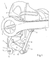
- eine perspektivische Frontansicht auf eine Sensoranordnung an einer nur teilweise dargestellten Radaufhängung,
- Fig. 2
- eine perspektivische Rückansicht auf die Sensoranordnung aus Fig. 1 und
- Fig. 3
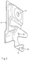
- eine räumliche Darstellung eines Sensorhalters nach der Erfindung.
- Fig. 1
- 2 shows a perspective front view of a sensor arrangement on a wheel suspension which is only partially shown,
- Fig. 2
- a rear perspective view of the sensor arrangement of FIGS. 1 and
- Fig. 3
- a spatial representation of a sensor holder according to the invention.
Entsprechend den Fig. 1 und 2 ist die erfindungsgemäße Sensoranordnung
an einer Radaufhängung 1 vorgesehen, mit der ein
nicht dargestelltes Rad eines im übrigen nicht dargestellten
Fahrzeuges an dessen Karosserie 2 angebracht ist. Im einzelnen
handelt es sich bei dem in den Fig. 1 und 2 dargestellten
Abschnitt der Radaufhängung 1 um den Lagerbereich eines als
Schwenkarm ausgebildeten Querlenkers 3 der Radaufhängung 1 an
der Fahrzeugkarosserie 2. Zur Anbringung des Querlenkers 3
ist an der Fahrzeugkarosserie 2 eine Lagerkonsole 4 ausgebildet,
an welcher der Querlenker 3 schwenkbar um eine Schwenkachse
5 gelagert ist.1 and 2 is the sensor arrangement according to the invention
provided on a
Die schwenkbare Befestigung des Querlenkers 3 an der Fahrzeugkarosserie
2 bzw. an deren Lagekonsole 4 wird mit Hilfe
eines als Befestigungsschraube ausgebildeten Lagerbolzens 6
hergestellt, der die Lagerkonsole 4 durchdringt und mit einem
nicht dargestellten Schwenklager des Querlenkers 3 verschraubt
ist. Das vorgenannte Schwenklager ist in einem Auge
7 des Querlenkers 3 angeordnet und der Übersichtlichkeit wegen
nicht dargestellt.The pivotable attachment of the
Der Lagerbolzen 6 durchdringt die Lagerkonsole 4 in einer dafür
vorgesehenen, in den Fig. 1 und 2 jedoch nicht sichtbaren
Öffnung, durch die die Relativlage der Schwenkachse 5 bezüglich
der Fahrzeugkarosserie 2 festgelegt wird. Um die im Rahmen
des Zusammenbaus der Radaufhängung sich aufsummierenden
Fertigungs- und Montagetoleranzen der einzelnen Bauteile auszugleichen,
wird die vorgenannte Öffnung für den Lagerbolzen
6 an der im übrigen weitgehend fertiggestellten Fahrzeugkarosserie
2 nachträglich angebracht. Dabei wir die Positionierung
der Öffnung in der Lagerkonsole 4 für den Lagerbolzen 6
in Abhängigkeit der sich für jeden Montagefall individuell
ergebenden, für eine optimale Funktionsfähigkeit der Radaufhängung
1 erforderlichen Relativlage zwischen Schwenkachse 5
und Fahrzeugkarosserie 2 durchgeführt.The
Gleichzeitig mit dem nicht dargestellten Schwenklager des
Querlenkers 3 wird mit Hilfe des Lagerbolzens 6 ein Sensorhalter
8 an der Fahrzeugkarosserie 2 befestigt. Bei der dargestellten
Ausführungsform wird der Sensorhalter 8 dabei nach
Art einer Unterlegscheibe auf der dem Schwenklager des Querlenkers
3 gegenüberliegenden Seite der Lagerkonsole 4 zwischen
dem Kopf des Lagerbolzens 6 und der Lagerkonsole 4 verspannt.
Der Lagerbolzen 6 bzw. die dafür in der Lagerkonsole
4 vorgesehene Öffnung bildet somit für den Querlenker 3 und
den Sensorhalter 8 eine gemeinsame Befestigungsstelle an der
Fahrzeugkarosserie 2.Simultaneously with the pivot bearing, not shown
Wishbone 3 becomes a sensor holder with the help of the
Entsprechend den Fig. 1 und 2 ist etwa senkrecht unterhalb
der Befestigungsstelle (Lagerbolzen 6) des Sensorhalters 8 an
der Fahrzeugkarosserie 2 am Sensorhalter 8 ein Sensor 9 befestigt.
Der Sensor 9 weist einen Schwenkhebel 10 auf, der
einenends um eine Schwenkhebelachse 11 am Sensor 9 gelagert
ist und der anderenends gelenkig mit einer Regelstange 12
verbunden ist. Die Regelstange 12 ist ihrerseits an ihrem vom
Schwenkhebel 10 abgewandten Ende an einer Anlenkstelle 13 gelenkig
mit dem Querlenker 3 verbunden. Auf diese Weise ist
der Sensor 9 mechanisch mit dem Querlenker 3 gekoppelt.
Schwenkbewegungen des Querlenkers 3 um seine Schwenkachse 5
werden von der Regelstange 12 auf den Schwenkhebel 10 übertragen
und somit vom Sensor 9 erfaßt. Bei bekannter Relativlage
des Sensors 9 bezüglich der Fahrzeugkarosserie 2 kann
daher über den Sensor 9 die Relativlage des Querlenkers 3 und
somit des daran gekoppelten Fahrzeugrades relativ zur Fahrzeugkarosserie
detektiert werden und beispielsweise in Form
von durch den Sensor 9 generierten Signalwerten an eine Niveauregulierungseinrichtung
weitergeleitet werden.1 and 2 is approximately perpendicular below
the fastening point (bearing pin 6) of the sensor holder 8
the
Da die Auslenkung des Schwenkhebels 10 am Sensor 9 das vom
Sensor 9 erfaßbare Eingangssignal bildet, müssen zum einen
die Schwenkachse 5 des Querlenkers 3 und die vorzugsweise
parallel dazu verlaufende Schwenkhebelachse 11 am Sensor 9
einen definierten Abstand voneinander aufweisen. Zum anderen
muß bei Vorliegen einer Referenzlage oder Ausgangs-Relativlage
des Querlenkers 3 eine definierte Ausgangsauslenkung
oder Ausgangsstellung für den Schwenkhebel 10 eingehalten
werden. Da der Abstand zwischen der Schwenkhebelachse 11
und der Schwenkachse 5 aufgrund der erfindungsgemäßen Anordnung
des Sensors 9 am Sensorhalter 8 einerseits und wegen der
gemeinsamen Befestigung des Sensorhalters 8 und des Querlenkers
3 an der Fahrzeugkarosserie 2 andererseits definiert
ist, muß zur Erzielung der erforderlichen Auslenkung des
Schwenkhebels 10 während der Montage des Sensorhalters 8 nur
noch ein bestimmter Winkel eingehalten werden, der sich zwischen
zwei sich in der Schwenkachse 5 schneidenden Geraden
ausbildet, wobei die erste Gerade durch die Anlenkstelle 13
der Regelstange 12 am Querlenker 3 und die zweite Gerade
durch die Schwenkhebelachse 11 verläuft.Since the deflection of the
Da die Referenzlage des Querlenkers 3 durch eine bestimmte
Relativlage des Querlenkers 3 bezüglich der Fahrzeugkarosserie
2 definiert ist, kann der vorgenannte Winkel dadurch eingestellt
werden, daß der Sensorhalter 8 in einer bestimmten
Relativlage bezüglich der Fahrzeugkarosserie 2 an dieser befestigt
wird.Since the reference position of the
Zum Auffinden dieser Relativlage des Sensorhalters 8 relativ
zur Fahrzeugkarosserie 2 sind Positioniermittel 14 und 15
vorgesehen. Im dargestellten Ausführungsbeispiel bestehen die
Positioniermittel aus einer Zunge 14, die am Sensorhalter 8
angebracht ist, und aus einer Öffnung 15, die an der Lagerkonsole
4 ausgebildet ist. Die Zunge 14 erstreckt sich von
dem Sensorhalter 8 etwa parallel zur Schwenkachse 5 in Richtung
auf die Lagerkonsole 4. Bei montiertem Sensorhalter 8
durchdringt die Zunge 14 dabei die Öffnung 15.To find this relative position of the sensor holder 8 relative
to the
Da die Referenzlage des Querlenkers 3 aufgrund der Fertigungs- und Montagetoleranzen im Rahmen der Endmontage der
Radaufhängung 1 bezüglich der vertikalen und horizontalen Anordnung
des Querlenkers 3 an der Fahrzeugkarosserie 2 unterschiedlich
ausfallen kann, weisen die Positioniermittel
(Zunge 14 und Öffnung 15) Spiel auf. Da die Positioniermittel
(14 und 15) etwa vertikal unterhalb der Befestigungsstelle
(Lagerbolzen 6) des Sensorhalters 8 an der Fahrzeugkarosserie
2 angeordnet sind, braucht das genannten Spiel im wesentlichen
nur in vertikaler Richtung ausgebildet sein. Dieses Vertikalspiel
wird bei der dargestellten Ausführungsform dadurch
erreicht, daß die Öffnung 15 als vertikal verlaufendes Langloch
ausgebildet ist.Since the reference position of the
Wenn die vorgenannten Fertigungs- und Montagetoleranzen eine
Veränderung der Relativlage des Querlenkers 3 bezüglich der
Fahrzeugkarosserie 2 in horizontaler Richtung bewirken, kann
dies durch eine geringfügige Drehverstellung des Sensorhalters
8 ausgeglichen werden, wobei sich die Zunge 14 in der
Öffnung 15 leicht drehen kann. Dementsprechend weisen die Positioniermittel
(Zunge 14 und Öffnung 15) wenig Horizontalspiel
auf.If the aforementioned manufacturing and assembly tolerances
Change in the relative position of the
Auftretende Abweichungen zwischen der gewünschten Soll-Relativlage
des Sensorhalters 8 bezüglich des Querlenkers 3
in dessen Referenzstellung, können beispielsweise durch eine
elektronische Kalibrierung ausgeglichen werden, bei der sich
aufgrund der Anordnung von Schwenkhebel 10 und Regelstange 12
kaum eine Beeinträchtigung für den Meßbereich oder die Meßgenauigkeit
des Sensors 9 ergibt.Deviations occurring between the desired target relative position
the sensor holder 8 with respect to the
Entsprechend Fig. 3 ist die Zunge 14 des Sensorhalters 8 an
ihrem freien Ende konvergierend ausgebildet. Durch diese Maßnahme
wird eine automatisierte Montage des Sensorhalters 8
vereinfacht, da im Verlaufe einer maschinell durchgeführten
Aufsteckbewegung die vorangehende Spitze der Zunge 14 leicht
in die Öffnung 15 eindringen kann. Im weiteren Verlaufe der
Aufsteckbewegung bewirkt die breiter werdende Zunge 14 eine
Ausichtung des Sensorhalters 8 relativ zur Fahrzeugkarosserie
2. Im Sensorhalter 8 sind Öffnungen 16 vorgesehen, die zur
Positionierung und Befestigung des Sensors 9 dienen. Außerdem
weist der Sensorhalter 8 eine Öffnung 17 auf, durch die der
Lagerbolzen 6 für die Befestigung des Sensorhalters 8 an der
Fahrzeugkarosserie 2 den Sensorhalter 8 durchdringt.3, the
Da erfindungsgemäß eine gemeinsame Befestigungsstelle der Lagerbolzen
6 für ein sensorseitiges Befestigungselement
(Sensorhalter 8) und ein schwenkarmseitiges Befestigungselement
(nicht dargestelltes Schwenklager des Querlenkers 3) an
der Fahrzeugkarosserie 2 vorgesehen ist, können sich Fertigungs- und Montagetoleranzen aller übrigen Bauteile der
Radaufhängung 1 nicht auf den Abstand des Sensors 9 zur
Schwenkachse 5 auswirken. Ein Toleranzausgleich ist diesbezüglich
somit nicht mehr erforderlich. Jedoch ist bei der
Herstellung des Sensorhalters 8 insbesondere darauf zu achten,
daß zum einen die relative Lage der Öffnungen 16 für die
Befestigung des Sensors 9 hinsichtlich der Öffnung 17 für den
Lagerbolzen 6 in einem vergleichsweise engen Toleranzbereich
ausgebildet werden. Zum anderen können die genannten Öffnungen
16 und 17 zentrierende Eigenschaften aufweisen, was beispielsweise
durch eine enge Passung, insbesondere eine Preßpassung,
realisiert werden kann.Since according to the invention a common attachment point of the
Anstelle des im Ausführungsbeispiel dargestellten separaten
Sensorhalters 8 kann auch ein Gehäuse des Sensors 9 entsprechend
ausgebildet sein und z.B. die Öffnung 17 für den Lagerbolzen
6 enthalten und mit entsprechenden Positioniermitteln
ausgestattet sein.Instead of the separate shown in the embodiment
Sensor holder 8 can also correspond to a housing of
Claims (12)
dadurch gekennzeichnet,
wobei das sensorseitige Befestigungselement durch eine sensorfeste Sensorhalterung (8) gebildet ist und wobei das schwenkarmseitige Befestigungselement ein Schwenklager des Schwenkarmes (3) ist, durch das der Schwenkarm (3) an der Fahrzeugkarosserie (2) schwenkbar befestigt ist.
characterized by
wherein the sensor-side fastening element is formed by a sensor-fixed sensor holder (8) and wherein the swivel arm-side fastening element is a swivel bearing of the swivel arm (3), by means of which the swivel arm (3) is pivotably fastened to the vehicle body (2).
dadurch gekennzeichnet,
characterized by
dadurch gekennzeichnet,
characterized by
dadurch gekennzeichnet,
characterized by
dadurch gekennzeichnet,
characterized by
dadurch gekennzeichnet,
characterized by
dadurch gekennzeichnet,
characterized by
dadurch gekennzeichnet,
characterized by
dadurch gekennzeichnet,
characterized by
dadurch gekennzeichnet,
characterized by
dadurch gekennzeichnet,
characterized by
Applications Claiming Priority (2)
| Application Number | Priority Date | Filing Date | Title |
|---|---|---|---|
| DE19831248A DE19831248C2 (en) | 1998-07-11 | 1998-07-11 | Sensor arrangement on a wheel suspension for a vehicle |
| DE19831248 | 1998-07-11 |
Publications (2)
| Publication Number | Publication Date |
|---|---|
| EP0972660A1 true EP0972660A1 (en) | 2000-01-19 |
| EP0972660B1 EP0972660B1 (en) | 2002-12-18 |
Family
ID=7873820
Family Applications (1)
| Application Number | Title | Priority Date | Filing Date |
|---|---|---|---|
| EP99111629A Expired - Lifetime EP0972660B1 (en) | 1998-07-11 | 1999-06-16 | Sensor assembly at a wheel suspension for a vehicle |
Country Status (4)
| Country | Link |
|---|---|
| US (1) | US6126177A (en) |
| EP (1) | EP0972660B1 (en) |
| JP (1) | JP2000079817A (en) |
| DE (1) | DE19831248C2 (en) |
Cited By (3)
| Publication number | Priority date | Publication date | Assignee | Title |
|---|---|---|---|---|
| WO2008074309A1 (en) * | 2006-12-21 | 2008-06-26 | Zf Friedrichshafen Ag | Wheel suspension for a vehicle |
| DE102014012587A1 (en) | 2014-08-26 | 2016-03-03 | Audi Ag | Device and method for level control on a chassis |
| WO2016041832A1 (en) * | 2014-09-17 | 2016-03-24 | Continental Teves Ag & Co. Ohg | Displacement sensor for a motor vehicle |
Families Citing this family (17)
| Publication number | Priority date | Publication date | Assignee | Title |
|---|---|---|---|---|
| US6357766B1 (en) * | 1999-11-01 | 2002-03-19 | Dana Corporation | Multi-axis suspension system |
| US6566864B1 (en) * | 2000-09-01 | 2003-05-20 | Ford Global Technologies, L.L.C. | Angular position sensor for vehicle suspension |
| DE10221873A1 (en) * | 2002-05-15 | 2003-11-27 | Zf Lemfoerder Metallwaren Ag | Rubber bearing for vehicle suspension linkage with compression sensor for headlamp adjustment has at least one sensor in or on bearing that detects relative movement of vehicle parts joined by bearing |
| JP2004270832A (en) * | 2003-03-10 | 2004-09-30 | Advics:Kk | Vibration control device for suspension and suspension mechanism using it |
| DE10333997B4 (en) * | 2003-07-25 | 2014-07-17 | Volkswagen Ag | Sensor arrangement for a land vehicle |
| US7360756B2 (en) * | 2005-03-31 | 2008-04-22 | Delphi Technologies, Inc. | Vibration isolating bushing with embedded speed/position sensor |
| US7370853B2 (en) | 2005-03-31 | 2008-05-13 | Delphi Technologies, Inc. | Vibration isolating bushing with embedded angular position sensor |
| US20060220638A1 (en) * | 2005-03-31 | 2006-10-05 | Urquidi Carlos A | Angular position sensor |
| KR100736716B1 (en) | 2007-01-08 | 2007-07-09 | 씨멘스브이디오한라 주식회사 | Vehicle wheel speed sensor and apparatus for forming its |
| DE102007028265A1 (en) | 2007-06-15 | 2008-12-18 | Ipgate Ag | Rotational angle sensor for determining rotary angle between lever and carrier of lever system, has sensor unit for detecting position of connection unit or target arranged at connection unit, relative to sensor housing and/or sensor unit |
| JP2009052918A (en) * | 2007-08-23 | 2009-03-12 | Nippon Soken Inc | Apparatus for detecting force acting on tire |
| US8567245B2 (en) * | 2007-12-07 | 2013-10-29 | Mitsubishi Electric Corporation | Vehicle speed detection unit and wheel attachment unit |
| US20100308192A1 (en) * | 2008-01-31 | 2010-12-09 | Zf Friedrichshafen Ag | Sensor attachment arrangement |
| WO2016157439A1 (en) * | 2015-03-31 | 2016-10-06 | 本田技研工業株式会社 | Support structure for wheel speed sensor |
| WO2019210944A1 (en) * | 2018-05-02 | 2019-11-07 | HELLA GmbH & Co. KGaA | Level sensor for detecting a movement of a suspension arm and vehicle assembly with the level sensor |
| DE202020106260U1 (en) * | 2020-11-02 | 2022-02-08 | Dana Italia S.R.L. | Vehicle suspension system with a sensor |
| WO2022162676A1 (en) * | 2021-02-01 | 2022-08-04 | Ree Automotive Ltd. | Apparatus for measuring steering angle |
Citations (10)
| Publication number | Priority date | Publication date | Assignee | Title |
|---|---|---|---|---|
| GB2028513A (en) * | 1978-06-23 | 1980-03-05 | Atsugi Motor Parts Co Ltd | Vehicle level detector |
| EP0094857A1 (en) * | 1982-05-06 | 1983-11-23 | HURET ET SES FILS Société dite: | Sensor apparatus, especially for driving a cycle odometer |
| US4756374A (en) * | 1987-03-31 | 1988-07-12 | Bailey John D | Vehicle load sensing device |
| US4838563A (en) * | 1987-05-27 | 1989-06-13 | Nissan Motor Company, Limited | Mounting structure for vehicle height sensor |
| DE3919040A1 (en) | 1989-06-10 | 1990-12-13 | Porsche Ag | METHOD AND DEVICE FOR ADJUSTING A LEVEL CONTROL SYSTEM OF A VEHICLE |
| US5032821A (en) * | 1989-05-12 | 1991-07-16 | Domanico Edward J | Motor vehicle stability monitoring and alarm system and method |
| EP0632253A1 (en) * | 1993-06-23 | 1995-01-04 | CTS Corporation | Position sensors |
| DE4429856C1 (en) | 1994-08-23 | 1995-09-07 | Daimler Benz Ag | Vehicle level discriminator |
| JPH08142907A (en) * | 1994-11-17 | 1996-06-04 | Delta:Kk | Rear wheel camber/tracking regulation device |
| JPH09105662A (en) * | 1995-10-09 | 1997-04-22 | Hino Motors Ltd | Axle load detector used for tandem axle trunnion type rear suspension |
Family Cites Families (8)
| Publication number | Priority date | Publication date | Assignee | Title |
|---|---|---|---|---|
| NL123252C (en) * | 1957-11-28 | |||
| GB1017391A (en) * | 1961-03-09 | 1966-01-19 | Automotive Prod Co Ltd | Improvements in and relating to valves for fluid pressure braking systems |
| US4553773A (en) * | 1983-08-05 | 1985-11-19 | Lear Siegler, Inc. | Load equalizer valve and suspension system |
| US4614247A (en) * | 1984-10-26 | 1986-09-30 | Airstream, Inc. | Composite multi-axle suspension for vehicles |
| US4982972A (en) * | 1989-12-26 | 1991-01-08 | Eaton Corporation | Hydraulic pump and actuator for parallel auxiliary leaf spring |
| US5033762A (en) * | 1990-02-26 | 1991-07-23 | Rakowski Carl F | Suspension system for a sidecar motorcycle |
| JPH06282368A (en) * | 1993-02-01 | 1994-10-07 | Wacom Co Ltd | Position information input system for information processor |
| JPH07287835A (en) * | 1994-02-25 | 1995-10-31 | Toyo Ink Mfg Co Ltd | Magnetic recording medium |
-
1998
- 1998-07-11 DE DE19831248A patent/DE19831248C2/en not_active Expired - Lifetime
-
1999
- 1999-06-16 EP EP99111629A patent/EP0972660B1/en not_active Expired - Lifetime
- 1999-07-08 US US09/349,099 patent/US6126177A/en not_active Expired - Fee Related
- 1999-07-08 JP JP11227853A patent/JP2000079817A/en active Pending
Patent Citations (10)
| Publication number | Priority date | Publication date | Assignee | Title |
|---|---|---|---|---|
| GB2028513A (en) * | 1978-06-23 | 1980-03-05 | Atsugi Motor Parts Co Ltd | Vehicle level detector |
| EP0094857A1 (en) * | 1982-05-06 | 1983-11-23 | HURET ET SES FILS Société dite: | Sensor apparatus, especially for driving a cycle odometer |
| US4756374A (en) * | 1987-03-31 | 1988-07-12 | Bailey John D | Vehicle load sensing device |
| US4838563A (en) * | 1987-05-27 | 1989-06-13 | Nissan Motor Company, Limited | Mounting structure for vehicle height sensor |
| US5032821A (en) * | 1989-05-12 | 1991-07-16 | Domanico Edward J | Motor vehicle stability monitoring and alarm system and method |
| DE3919040A1 (en) | 1989-06-10 | 1990-12-13 | Porsche Ag | METHOD AND DEVICE FOR ADJUSTING A LEVEL CONTROL SYSTEM OF A VEHICLE |
| EP0632253A1 (en) * | 1993-06-23 | 1995-01-04 | CTS Corporation | Position sensors |
| DE4429856C1 (en) | 1994-08-23 | 1995-09-07 | Daimler Benz Ag | Vehicle level discriminator |
| JPH08142907A (en) * | 1994-11-17 | 1996-06-04 | Delta:Kk | Rear wheel camber/tracking regulation device |
| JPH09105662A (en) * | 1995-10-09 | 1997-04-22 | Hino Motors Ltd | Axle load detector used for tandem axle trunnion type rear suspension |
Non-Patent Citations (2)
| Title |
|---|
| PATENT ABSTRACTS OF JAPAN vol. 1996, no. 10 31 October 1996 (1996-10-31) * |
| PATENT ABSTRACTS OF JAPAN vol. 1997, no. 08 29 August 1997 (1997-08-29) * |
Cited By (6)
| Publication number | Priority date | Publication date | Assignee | Title |
|---|---|---|---|---|
| WO2008074309A1 (en) * | 2006-12-21 | 2008-06-26 | Zf Friedrichshafen Ag | Wheel suspension for a vehicle |
| US8179128B2 (en) | 2006-12-21 | 2012-05-15 | Zf Friedrichshafen Ag | Wheel suspension for a vehicle |
| DE102014012587A1 (en) | 2014-08-26 | 2016-03-03 | Audi Ag | Device and method for level control on a chassis |
| DE102014012587B4 (en) * | 2014-08-26 | 2016-05-04 | Audi Ag | Device and method for level control on a chassis |
| WO2016041832A1 (en) * | 2014-09-17 | 2016-03-24 | Continental Teves Ag & Co. Ohg | Displacement sensor for a motor vehicle |
| CN107076572A (en) * | 2014-09-17 | 2017-08-18 | 大陆-特韦斯股份有限公司 | Displacement sensing equipment for motor vehicle |
Also Published As
| Publication number | Publication date |
|---|---|
| DE19831248A1 (en) | 2000-01-20 |
| DE19831248C2 (en) | 2002-09-19 |
| US6126177A (en) | 2000-10-03 |
| EP0972660B1 (en) | 2002-12-18 |
| JP2000079817A (en) | 2000-03-21 |
Similar Documents
| Publication | Publication Date | Title |
|---|---|---|
| DE19831248C2 (en) | Sensor arrangement on a wheel suspension for a vehicle | |
| DE19739298C1 (en) | Appliance for mounting distance sensor on motor vehicle esp. for radar equipment measuring distance between vehicles | |
| EP0694465B1 (en) | Motorcarbody with a structural cross beam | |
| WO1992008136A1 (en) | Sensor-positioning device | |
| DE10304259B4 (en) | Attachment for a display unit | |
| EP2828680B1 (en) | Sensor holder for a sensor for object detection | |
| EP1444114B1 (en) | Positioning device for adjustable housing | |
| DE102005053181A1 (en) | Device for a steering system of a motor vehicle | |
| DE102007002699A1 (en) | Attachment device, particularly for motor vehicle for arrangement of attachment part at carrying component, has threaded piece which is fixed by mounting component and adjusted transverse to attachment direction of mounting component | |
| DE10003981C2 (en) | Arrangement for the correct connection of components | |
| DE102020208490A1 (en) | Chassis component with an inner joint part | |
| DE102012022783A1 (en) | Mounting arrangement for vehicle, has fastening points spaced from body-mounted component in vertical direction, and compensating part arranged in points for angle correction of cross beam relative to component in xz plane | |
| DE10130411C2 (en) | Wiper carrier unit | |
| WO2007054397A1 (en) | Acceleration sensor and bumper cover | |
| DE4429856C1 (en) | Vehicle level discriminator | |
| EP1341642B1 (en) | Method and device for assembling a vehicle door | |
| DE102015119710A1 (en) | Device for fastening an optical sensor to a motor vehicle with spring element, sensor arrangement and motor vehicle | |
| DE102004005978B4 (en) | Method and device for mounting headlamps to mounting brackets | |
| DE4313739C2 (en) | Device for attaching a second component to a first component | |
| DE102021103364B9 (en) | Calibration unit for aligning vehicle surroundings detection units of a motor vehicle | |
| DE60014565T2 (en) | Eccentrically adjustable nut | |
| DE102017219495A1 (en) | Tolerance compensation system for adjusting a joint pattern between two outer panels to be mounted in the region of a vehicle pillar of a motor vehicle | |
| DE102021121798A1 (en) | Door drive device with a sensor device for measuring a force in the power flow | |
| DE19837584C2 (en) | Method of attaching a sensor | |
| DE102015119708A1 (en) | Device for fastening an optical sensor to a motor vehicle with adjustment device, sensor arrangement and motor vehicle |
Legal Events
| Date | Code | Title | Description |
|---|---|---|---|
| PUAI | Public reference made under article 153(3) epc to a published international application that has entered the european phase |
Free format text: ORIGINAL CODE: 0009012 |
|
| AK | Designated contracting states |
Kind code of ref document: A1 Designated state(s): FR GB IT SE |
|
| AX | Request for extension of the european patent |
Free format text: AL;LT;LV;MK;RO;SI |
|
| 17P | Request for examination filed |
Effective date: 19991201 |
|
| AKX | Designation fees paid |
Free format text: FR GB IT SE |
|
| 17Q | First examination report despatched |
Effective date: 20011210 |
|
| REG | Reference to a national code |
Ref country code: DE Ref legal event code: 8566 |
|
| GRAH | Despatch of communication of intention to grant a patent |
Free format text: ORIGINAL CODE: EPIDOS IGRA |
|
| GRAH | Despatch of communication of intention to grant a patent |
Free format text: ORIGINAL CODE: EPIDOS IGRA |
|
| GRAA | (expected) grant |
Free format text: ORIGINAL CODE: 0009210 |
|
| PUAC | Information related to the publication of a b1 document modified or deleted |
Free format text: ORIGINAL CODE: 0009299EPPU |
|
| STAA | Information on the status of an ep patent application or granted ep patent |
Free format text: STATUS: THE APPLICATION HAS BEEN WITHDRAWN |
|
| AK | Designated contracting states |
Kind code of ref document: B1 Designated state(s): FR GB IT SE |
|
| REG | Reference to a national code |
Ref country code: GB Ref legal event code: FG4D Free format text: NOT ENGLISH |
|
| DB1 | Publication of patent cancelled | ||
| 18W | Application withdrawn |
Withdrawal date: 20021116 |
|
| GBV | Gb: ep patent (uk) treated as always having been void in accordance with gb section 77(7)/1977 [no translation filed] |
Effective date: 20021218 |
|
| EN | Fr: translation not filed |