EP0632253A1 - Position sensors - Google Patents
Position sensors Download PDFInfo
- Publication number
- EP0632253A1 EP0632253A1 EP94304453A EP94304453A EP0632253A1 EP 0632253 A1 EP0632253 A1 EP 0632253A1 EP 94304453 A EP94304453 A EP 94304453A EP 94304453 A EP94304453 A EP 94304453A EP 0632253 A1 EP0632253 A1 EP 0632253A1
- Authority
- EP
- European Patent Office
- Prior art keywords
- rotor
- position sensor
- shaft
- sensor
- rotary
- Prior art date
- Legal status (The legal status is an assumption and is not a legal conclusion. Google has not performed a legal analysis and makes no representation as to the accuracy of the status listed.)
- Granted
Links
Images


Classifications
-
- G—PHYSICS
- G01—MEASURING; TESTING
- G01D—MEASURING NOT SPECIALLY ADAPTED FOR A SPECIFIC VARIABLE; ARRANGEMENTS FOR MEASURING TWO OR MORE VARIABLES NOT COVERED IN A SINGLE OTHER SUBCLASS; TARIFF METERING APPARATUS; MEASURING OR TESTING NOT OTHERWISE PROVIDED FOR
- G01D5/00—Mechanical means for transferring the output of a sensing member; Means for converting the output of a sensing member to another variable where the form or nature of the sensing member does not constrain the means for converting; Transducers not specially adapted for a specific variable
- G01D5/12—Mechanical means for transferring the output of a sensing member; Means for converting the output of a sensing member to another variable where the form or nature of the sensing member does not constrain the means for converting; Transducers not specially adapted for a specific variable using electric or magnetic means
- G01D5/14—Mechanical means for transferring the output of a sensing member; Means for converting the output of a sensing member to another variable where the form or nature of the sensing member does not constrain the means for converting; Transducers not specially adapted for a specific variable using electric or magnetic means influencing the magnitude of a current or voltage
- G01D5/16—Mechanical means for transferring the output of a sensing member; Means for converting the output of a sensing member to another variable where the form or nature of the sensing member does not constrain the means for converting; Transducers not specially adapted for a specific variable using electric or magnetic means influencing the magnitude of a current or voltage by varying resistance
- G01D5/165—Mechanical means for transferring the output of a sensing member; Means for converting the output of a sensing member to another variable where the form or nature of the sensing member does not constrain the means for converting; Transducers not specially adapted for a specific variable using electric or magnetic means influencing the magnitude of a current or voltage by varying resistance by relative movement of a point of contact or actuation and a resistive track
-
- G—PHYSICS
- G01—MEASURING; TESTING
- G01D—MEASURING NOT SPECIALLY ADAPTED FOR A SPECIFIC VARIABLE; ARRANGEMENTS FOR MEASURING TWO OR MORE VARIABLES NOT COVERED IN A SINGLE OTHER SUBCLASS; TARIFF METERING APPARATUS; MEASURING OR TESTING NOT OTHERWISE PROVIDED FOR
- G01D11/00—Component parts of measuring arrangements not specially adapted for a specific variable
- G01D11/20—Caging devices for moving parts when not in use
-
- B—PERFORMING OPERATIONS; TRANSPORTING
- B60—VEHICLES IN GENERAL
- B60G—VEHICLE SUSPENSION ARRANGEMENTS
- B60G2400/00—Indexing codes relating to detected, measured or calculated conditions or factors
- B60G2400/25—Stroke; Height; Displacement
- B60G2400/252—Stroke; Height; Displacement vertical
-
- B—PERFORMING OPERATIONS; TRANSPORTING
- B60—VEHICLES IN GENERAL
- B60G—VEHICLE SUSPENSION ARRANGEMENTS
- B60G2401/00—Indexing codes relating to the type of sensors based on the principle of their operation
-
- Y—GENERAL TAGGING OF NEW TECHNOLOGICAL DEVELOPMENTS; GENERAL TAGGING OF CROSS-SECTIONAL TECHNOLOGIES SPANNING OVER SEVERAL SECTIONS OF THE IPC; TECHNICAL SUBJECTS COVERED BY FORMER USPC CROSS-REFERENCE ART COLLECTIONS [XRACs] AND DIGESTS
- Y10—TECHNICAL SUBJECTS COVERED BY FORMER USPC
- Y10T—TECHNICAL SUBJECTS COVERED BY FORMER US CLASSIFICATION
- Y10T29/00—Metal working
- Y10T29/49—Method of mechanical manufacture
- Y10T29/49002—Electrical device making
- Y10T29/49082—Resistor making
-
- Y—GENERAL TAGGING OF NEW TECHNOLOGICAL DEVELOPMENTS; GENERAL TAGGING OF CROSS-SECTIONAL TECHNOLOGIES SPANNING OVER SEVERAL SECTIONS OF THE IPC; TECHNICAL SUBJECTS COVERED BY FORMER USPC CROSS-REFERENCE ART COLLECTIONS [XRACs] AND DIGESTS
- Y10—TECHNICAL SUBJECTS COVERED BY FORMER USPC
- Y10T—TECHNICAL SUBJECTS COVERED BY FORMER US CLASSIFICATION
- Y10T29/00—Metal working
- Y10T29/49—Method of mechanical manufacture
- Y10T29/49815—Disassembling
- Y10T29/49822—Disassembling by applying force
- Y10T29/49824—Disassembling by applying force to elastically deform work part or connector
-
- Y—GENERAL TAGGING OF NEW TECHNOLOGICAL DEVELOPMENTS; GENERAL TAGGING OF CROSS-SECTIONAL TECHNOLOGIES SPANNING OVER SEVERAL SECTIONS OF THE IPC; TECHNICAL SUBJECTS COVERED BY FORMER USPC CROSS-REFERENCE ART COLLECTIONS [XRACs] AND DIGESTS
- Y10—TECHNICAL SUBJECTS COVERED BY FORMER USPC
- Y10T—TECHNICAL SUBJECTS COVERED BY FORMER US CLASSIFICATION
- Y10T29/00—Metal working
- Y10T29/49—Method of mechanical manufacture
- Y10T29/49826—Assembling or joining
- Y10T29/4984—Retaining clearance for motion between assembled parts
-
- Y—GENERAL TAGGING OF NEW TECHNOLOGICAL DEVELOPMENTS; GENERAL TAGGING OF CROSS-SECTIONAL TECHNOLOGIES SPANNING OVER SEVERAL SECTIONS OF THE IPC; TECHNICAL SUBJECTS COVERED BY FORMER USPC CROSS-REFERENCE ART COLLECTIONS [XRACs] AND DIGESTS
- Y10—TECHNICAL SUBJECTS COVERED BY FORMER USPC
- Y10T—TECHNICAL SUBJECTS COVERED BY FORMER US CLASSIFICATION
- Y10T29/00—Metal working
- Y10T29/49—Method of mechanical manufacture
- Y10T29/49826—Assembling or joining
- Y10T29/49945—Assembling or joining by driven force fit
Definitions
- This invention relates generally to position sensors and more especially but not exclusively to a variable resistor position sensor, for example as used in connection with throttle valves for internal combustion engines.
- throttle valve to control the amount of air entering the engine.
- This throttle valve is often called a butterfly or throttle flap, and is used in gasoline, diesel and other alternatively fuelled vehicles.
- the throttle valve may either be opened to provide unimpeded air intake through a throttle body or may be closed more or less to restrict the passage of air.
- the throttle valve forms part of the primary engine speed control.
- the throttle valve may therefore be mechanically linked to the accelerator pedal or, in some instances, linked thereto through a combination of electrical and mechanical interconnections.
- the electronic circuitry monitors various engine parameters and provides feedback to control the engine.
- the feedback may be a signal which in some way improves efficiency or reduces emissions.
- the signal may, for example, be used to control the amount of fuel injected into the engine or the timing of ignition.
- a potentiometer is often used to sense the position of the throttle valve. This potentiometer is in some ways similar to volume controls used in radio and television receivers. A voltage is applied across two extreme ends of a resistor, and an intermediate tap is mechanically linked to the device which is to be sensed, the position of the device being determined by the voltage at the intermediate tap.
- the automotive environmental requirements are also different from a radio or television receiver.
- the throttle position sensor must reside against the throttle body.
- environmental temperatures might, for example, range from -55 to +150 degrees Celsius.
- the device may be exposed to a number of solvents, road spray, and other adverse conditions associated with engine compartment environments. These requirements diverge greatly from those of the typical volume control.
- Examples of conventional throttle position sensors include U.S. Patents No. 4 430 634, No. 4 355 293 and No. 5 133 321.
- Other examples may be found in U.S. Patents Nos. 4 616 504, 4 621 250, 4 688 420, 4 703 649, 4 715 220, 4 719 795, 4 743 882, 4 812 803, 4 933 661, 5 133 321 and Japanese Patent Publication No. 58-70104.
- the throttle position sensor in the prior art is a free-standing, effectively self-contained device.
- a well-sealed package including the necessary associated bearings is typically provided.
- Significant effort has been directed to designing a package that is sealed against the adverse chemicals and moisture that might otherwise damage the sensor.
- the shape of the contactor structure is, for obvious reasons, critical to the performance of the device. Where contactor rakes are used, a bent rake may reduce the life of the device to less than one hundredth the normal life. Yet, in those devices that mount into the throttle wall, the contactor will be exposed during shipment of service parts and will be handled to an undesirable degree during installation.
- the present invention seeks to overcome the limitations of the prior art sensors and offer a throttle position sensor that delivers substantially improved performance without compromise. Further, while the preferred embodiment is throttle position sensing, the inventive features are applicable to position sensors in other applications, including but not limited to accelerator pedal position sensing, machine and industrial robot position sensing, and other applications for potentiometric devices of high quality and reliability.
- the present invention in one aspect, provides a rotary potentiometric device which includes a sensor element traversed by a contactor, wherein, prior to final installation the contactor and rotor are supported by a unique retaining mechanism that protects the integrity of the device post-production and pre-installation, and, at the time of installation, the rotor is released from the retaining mechanism, so the rotor will freely follow a rotary shaft.
- This combination of features uniquely protects the device after production while eliminating the need for bearings and springs found in the prior art.
- the present invention provides a rotary position sensor for coupling to and sensing the rotary position of a device rotatable about an axis of the device, the sensor comprising: a rotor means which in a first position is angularly rotated about its axis relative to a first reference axis perpendicular to said rotor axis by a first angle and is rotatable to a second position angularly rotated about said rotor axis relative to said first reference axis by a second angle; and means for converting said second angle into an electrical signal indicative of a magnitude of said second angle; characterised by means for supporting said rotor means in said first position whilst permitting said rotor means to be fully detached from said supporting means in said second position but remaining fully supported by said device.
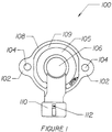
- the position sensor is designated generally by the numeral 100.
- This sensor 100 is shown in Figures 1 to 3 in an "as manufactured" condition prior to installation.
- O-ring 180 later referred to, is not illustrated for exemplary purposes.
- the sensor 100 includes mounting ears 102 with holes 104 therethrough. Holes 104 are used by attachment devices (not shown) such as bolts to pass through and attach to a throttle body (not shown). Ears 102 provide easy access, particularly where a hex-head type bolt is used.
- a rim 108 is provided generally at the outer periphery of the sensor 100, and adjacent rim 108 is a groove 109.
- the rim 108 and groove 109 provide a relatively stiff periphery to the sensor 100, analogously to an I-beam, while not consuming an excess of material in the manufacture.
- a dome 105 rises from the rim 108 and the groove 109, forming a wall of the sensor chamber.
- a second dome 106 rises from the dome 105, forming an outer wall of the rotor chamber.
- the sensor 100 at a bottom thereof includes an electrical connector wall 110 of generally cylindrical configuration, with a protrusion 112 extending therefrom. This protrusion 112 forms a polarising key to ensure that a mating electrical connector (not shown) is inserted properly. Additionally, the protrusion 112 forms a positive mechanical latch to help retain the mating connector in an engaged position.
- the sensor 100 At the time of installation, an installer will probably be viewing the sensor 100 from an orientation similar to that shown in Figure 1, which is referred to herein as the top for convenience purposes.
- the part will be mounted against a throttle body, with the bottom opposite that of Figure 1 pressed or abutted with the throttle body.
- the locating pin 118 inserts into a mating hole, while fasteners extend through the holes 104 in ears 102 and are fastened to suitable structure upon the throttle body. Assuming the fasteners to be bolts, the bolts are then tightened down against the ears 102, bringing the sensor 100 tight against the throttle body.
- the sensor 100 further includes tapered guides 116 on the outer circumference of lip 114.
- the electrical connector wall 110 partially encloses electrical connector terminals 122, 124 and 126. While male blades are illustrated, there are a wide variety of known types of suitable electrical connectors.
- Surface 120 may be formed integrally with the housing around the electrical connector terminals 122, 124 and 126, preferably in a sealed manner such as to exclude dirt and other contaminants.
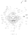
- Figures 4 and 5 illustrate the sensor 100 with alterations for viewing purposes that make these parts different from the "as manufactured" views of Figures 1 to 3.
- cover 170 visible in Figure 5
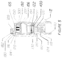
- Figure 5 is a cutaway view of the sensor 100 taken along section line 5' of Figure 4. To avoid duplication, like numbering has been used to Figures 1 to 3, so already discussed components will not be repeated.
- the view in Figure 4 is from the bottom side, or the side that will be mounted against the throttle body. As noted, cover 170 is removed to allow a view of each of the internal components. Central in Figure 4 is rotor structure 200 carrying thereon contactor structure 300. The details of each of these structures will be discussed elsewhere.
- a throttle shaft (not shown) will be inserted into throttle shaft opening 202.
- the sensor 100 will then be rotated just a few degrees, thereby releasing rotor structure 200 from any contact with arms 130 and 132.
- the sensor 100 is then pressed towards the throttle body, using locating pin 118 and tapered guides 116 to help align the sensor 100 with the throttle body.
- a significant advantage is the lack of need for a return spring or bearing within the sensor package. This eliminates wear debris, reduces rotational torque, and does not impact adversely upon the return spring of the throttle shaft, which provides the feel of the accelerator to the engine operator.
- the bearing in the prior art formed one part of an enclosed package that allowed the prior art sensors to be free-standing and environmentally protected.
- this issue is addressed in part by O-ring channel 182 and O-ring 180, both of which are most clearly visible in Figure 5.
- the O-ring 180 is deformed and retained between the sensor 100 and the throttle body (not shown) at the time of installation. This O-ring provides a seal between the throttle body and sensor 100, thereby protecting the internal portions of sensor 100 from the remainder of the engine compartment.
- the O-ring channel 182, groove 109 and rim 108 form an I-beam type construction, providing sufficient structural integrity to ensure good compression of O-ring 180.
- Resistive element 150 is typically formed by screen printing conductive polymers upon a Kapton (Trade Mark) film, through the materials that make up element 150 are not the essential features to the construction.
- U.S. Patent No. 4 355 293 and other similar patents adequately illustrate the features of this type of element construction.
- the resistive element 150 is inserted into the housing, generally within and against the dome 105.
- One end of element 150 is captured in a pocket 142 comprised generally by a U-shaped wall 140 on a first end of the pocket 142 and two guide pieces 144 and 146 on the opposite end of the pocket 142.
- the element 150 would typically be inserted into the pocket 142 first at the U-shaped wall 140 and then slid down between the guide pieces 144 and 146.
- the pocket 142 serves to guide the insertion of the element 150 during assembly and also serves as a positive means for positioning the terminal end of element 150. Positioning is important since the element 150 must be connected through relativelv small terminations to the connector terminals 122, 124 and 126. Once the element 150 is inserted into the pocket 142, pressure wedge 400 is pressed into the pocket 142, forcing the element 150 against the exposed portions of connector terminals 122, 124 and 126. By virtue of this compression, sound electrical contact resistant to vibration is ensured.
- guides 144 and 146 are significant in ensuring correct deformation of the element 150 while preventing it from sagging into the region where the wedge 400 will be inserted. Too sharp a bend in the element 150 could result in destruction of the resistive and conductive coatings patterned thereupon, while an insufficient bend will result in the element 150 curving within pocket 142, exposing the element 150 to the possibility of being crushed upon insertion of the wedge 400.
- FIG. 5 shows in cross-sectional view the inside of the sensor 100. Many of the elements have already been described and will not be repeated. However, the cover 170 is shown in the installed positional. From the drawing it is apparent that the interior opening of the cover 170, closest to the rotor 200, has a diameter somewhat larger than required for the rotor 200. This provides a small amount of radial tolerance to the throttle shaft axial centre. This is desirable in case the rotor 200 centre is, prior to installation, not in exact axial alignment with the throttle shaft. Opening 168 also limits radial motion of the rotor 200 prior to throttle body installation, thereby preventing damage.
- chambers 192 and 194 formed by the domes 105 and 106, respectively.
- element 150 Within the chamber 192 is element 150, contactor 300, and, in most cases, an amount of lubricant (not shown) upon the element 150.
- the sensor 100 is pressed towards a throttle shaft.
- the throttle shaft should pass through throttle shaft opening 202, but in order to do so, the rotor structure 200 must be forced towards the throttle shaft. This force may be applied by axially moving the throttle shaft towards the dome 106. The force is then transmitted through the inner portion of the dome 106 to the rotor 200, causing the dome 106 and the rotor 200 to be in contact, as illustrated in Figure 5.
- the throttle shaft will be returned to a natural axial position, causing the rotor structure 200 to move away from the dome 106. Ideally, rotor 200 will then be separated from any direct contact with the dome 106.
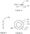
- FIGS 6 to 8 illustrate the cover in side, end and bottom views, respectively.
- the cover 170 has therein a large centre hole 168 of slightly larger diameter than the part of rotor structure 200 fitting therethrough. Additionally, the cover 170 has curved tabs 172 with spaces 174 and 176 interspersed between each tab 172.
- the tabs 172 form a flexible one-way engaging mechanism to engage the inner circumference of the lip 114. During installation, the cover 170 is pressed into the lip 114 and the tabs 172 resiliently flex towards the centre of the cover 170. However, removal of the cover 170 is prevented by the tabs 172 biting into the lip 114.
- the cover 170 may be made from a variety of materials, although a slightly resilient metal is preferred.
- the rotor structure 200 is illustrated in Figures 9 to 12, and includes a throttle shaft opening 202. At a first end of the opening 202 is a tapered surface 204 which serves to facilitate alignment of the throttle shaft with the rotor structure 200. At an end of the opening 202 opposite the tapered surface 204 is a slight extension 240, which provides a bearing surface of less than full circle through which force may be applied to force the rotor structure 200 onto the throttle shaft. The extension 240 extends beyond end 242 of the opening 202 so that if there is undesired drag between the rotor structure 200 and the dome 106 this is minimised.
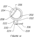
- extending axially with the opening 202 are two long grooves 206 and 208, and a compression wedge 207 which engages a flat upon the throttle shaft to ensure exact alignment between the rotor structure and the throttle shaft.
- the compression wedge 207 restricts the opening 202 to a size just smaller than the shaft size, forcing the rotor structure 202 to flex slightly to allow the throttle shaft to pass therethrough.
- the grooves 206 and 208 provide lines of flexure while ensuring that the compression wedge 207 is retained tightly against the flat of the throttle shaft.
- a contactor support block 220 which includes contactor support surfaces 230 for supporting a contactor such as the contactor 300, with contactor alignment edge 224 and alignment stubs 226.
- the contactor 300 is set against surfaces 230 and is heat staked in place by thermally deforming small heat stake protrusion 228, edge 224 and stubs 226. This structure serves to support the contactor 300 and ensures tracking between contactor 300 and the throttle shaft.
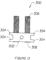
- Figure 13 illustrates the contactor 300 in further detail and Figure 14 illustrates the rotor structure 200 interconnected to the contactor 300, which is shown with brushes 306 protruding away from opposite edge 308, although it will be immediately apparent to those skilled in the art that brushes are but one of many choices available for contactor structures.
- Other configurations include paddles, spoons, rakes, multi-fingered contacts, blades, and others.
- Four small tabs 304 engage with and partially surround on three sides alignment stubs 226.
- the centre of the contactor 300 has a small hole 302 through which fits the heat stake protrusion 228.
- the edge 308 of contactor 300 is abutted with the alignment edge 224, the hole 302 is aligned with the heat stake protrusion 228, while the alignment stubs 226 are centred between the tabs 304.
- the contactor 300 is then pressed down against surfaces 230 and heat stake protrusion 228, edge 224 and stubs 226 are forced down to retain contactor 300 in place against surfaces 230.
- FIGS 15 to 18 illustrate the pressure wedge 400 in more detail.
- the wedge 400 is formed from a resilient material with high spring retention. Suitable materials include beryllium copper, phosphor bronze, spring steel and other similar materials. Plastics may alternatively be used, although a sufficient spring force must be generated to ensure sound electrical contact through temperature extremes.
- the wedge 400 has several protrusions 402 extending therefrom, which act as force concentrators and so are designed to press particularly against the resistive element 150 only in those places where the element 150 is to make sound electrical contact with the electrical connector terminals 122, 124 and 126 .
- the wedge 400 takes on a V-shape from side view, as illustrated in Figure 17.
- the base 404 of the wedge is joined and forms approximately a 30 degree included angle. Since there are three electrical connector terminals 122, 124 and 126 in the preferred embodiment, there are six legs extending from the base 404. While only two legs would be necessary at a minimum (one for each side of the V-shape) adding a leg for each protrusion 402 provides resilience for each contact point independent of each other.
- Figure 15 illustrates the wedge 400 as it would appear inserted into the pocket 142.
- the wedge in this compressed state takes on a more U-shaped geometry, with the protrusions 402 extending oppositely therefrom.
Abstract
Description
- This invention relates generally to position sensors and more especially but not exclusively to a variable resistor position sensor, for example as used in connection with throttle valves for internal combustion engines.
- Many internal combustion engines use a throttle valve to control the amount of air entering the engine. This throttle valve is often called a butterfly or throttle flap, and is used in gasoline, diesel and other alternatively fuelled vehicles. The throttle valve may either be opened to provide unimpeded air intake through a throttle body or may be closed more or less to restrict the passage of air. By controlling the amount of air that reaches the combustion chamber, the throttle valve forms part of the primary engine speed control. The throttle valve may therefore be mechanically linked to the accelerator pedal or, in some instances, linked thereto through a combination of electrical and mechanical interconnections.
- Many efforts are being made to improve the efficiency of internal combustion engines and similarly to reduce the emissions, or pollutants, that are produced by these engines. A vital part of better efficiency and reduced emissions is the electronic control circuitry used with the engines. The electronic circuitry monitors various engine parameters and provides feedback to control the engine. The feedback may be a signal which in some way improves efficiency or reduces emissions. The signal may, for example, be used to control the amount of fuel injected into the engine or the timing of ignition.
- A potentiometer is often used to sense the position of the throttle valve. This potentiometer is in some ways similar to volume controls used in radio and television receivers. A voltage is applied across two extreme ends of a resistor, and an intermediate tap is mechanically linked to the device which is to be sensed, the position of the device being determined by the voltage at the intermediate tap.
- There exist several stringent requirements placed upon a throttle position sensor that make it different from a volume control. Since the throttle valve is used to control air intake and thereby represent a demand for power, binding of the throttle shaft in an open throttle position could result in life threatening situations. Safety and reliability are essential in automotive applications.
- The automotive environmental requirements are also different from a radio or television receiver. The throttle position sensor must reside against the throttle body. Thus, environmental temperatures might, for example, range from -55 to +150 degrees Celsius. Further, the device may be exposed to a number of solvents, road spray, and other adverse conditions associated with engine compartment environments. These requirements diverge greatly from those of the typical volume control.
- Examples of conventional throttle position sensors include U.S. Patents No. 4 430 634, No. 4 355 293 and No. 5 133 321. Other examples may be found in U.S. Patents Nos. 4 616 504, 4 621 250, 4 688 420, 4 703 649, 4 715 220, 4 719 795, 4 743 882, 4 812 803, 4 933 661, 5 133 321 and Japanese Patent Publication No. 58-70104.
- In the prior art, a lever such as shown in U.S. Patents No. 4 355 293 and No. 4 430 634 or special drives such as shown in U.S. Patent No. 4 616 504 are proposed. These drives ensure that, even in the event of malfunction, the throttle sensor will not retain the throttle valve in an acceleration position, but instead will allow the throttle valve to return to the idle condition. Engagement between the sensor and the throttle shaft has thus necessitated the use of a return spring so that as the throttle shaft returns to idle position, the throttle position sensor also returns and tracks the position of the throttle valve.
- The throttle position sensor in the prior art is a free-standing, effectively self-contained device. In addition to the return spring, a well-sealed package including the necessary associated bearings is typically provided. Significant effort has been directed to designing a package that is sealed against the adverse chemicals and moisture that might otherwise damage the sensor.
- Inclusion of the spring and bearings into this sealed package has drawbacks. The use of springs requires a fairly robust design. Springs and bearings add expense to the device and increase the cost and hazards of assembly. Additionally, any wear debris that may result from the spring or bearings may be detrimental to the operation of the position sensor.
- Other prior art sensors incorporate the sensor directly into the throttle body. Exemplary of this concept are U.S. Patents Nos. 4 649 367, 4 672 356, 4 693 111, 4 718 272, 4 827 884, 4 886 981 and 5 070 728. This concept offers advantage in simplicity. However, there is little control over the element contactor interface, which has been determined to be very important for the life of the unit.
- Variations in contact pressure, contact orientation, lube and other similar factors all impair the performance of the device. Further, field replacement is important for service repair, and the service replacement should be of the same quality as the original device. These throttle body incorporated sensors do not have the precise control over lube thickness and composition, protection of vital components while shelved awaiting installation, and control over contactor and element relationships that are desirable features.
- The shape of the contactor structure is, for obvious reasons, critical to the performance of the device. Where contactor rakes are used, a bent rake may reduce the life of the device to less than one hundredth the normal life. Yet, in those devices that mount into the throttle wall, the contactor will be exposed during shipment of service parts and will be handled to an undesirable degree during installation.
- With electronics becoming more prevalent, the ability to sense various engine functions and also in some instances non-engine or indirect engine functions is more desirable. The present invention seeks to overcome the limitations of the prior art sensors and offer a throttle position sensor that delivers substantially improved performance without compromise. Further, while the preferred embodiment is throttle position sensing, the inventive features are applicable to position sensors in other applications, including but not limited to accelerator pedal position sensing, machine and industrial robot position sensing, and other applications for potentiometric devices of high quality and reliability.
- The present invention, in one aspect, provides a rotary potentiometric device which includes a sensor element traversed by a contactor, wherein, prior to final installation the contactor and rotor are supported by a unique retaining mechanism that protects the integrity of the device post-production and pre-installation, and, at the time of installation, the rotor is released from the retaining mechanism, so the rotor will freely follow a rotary shaft. This combination of features uniquely protects the device after production while eliminating the need for bearings and springs found in the prior art.
- Thus, in its most general aspect, the present invention provides a rotary position sensor for coupling to and sensing the rotary position of a device rotatable about an axis of the device, the sensor comprising:
a rotor means which in a first position is angularly rotated about its axis relative to a first reference axis perpendicular to said rotor axis by a first angle and is rotatable to a second position angularly rotated about said rotor axis relative to said first reference axis by a second angle; and
means for converting said second angle into an electrical signal indicative of a magnitude of said second angle;
characterised by
means for supporting said rotor means in said first position whilst permitting said rotor means to be fully detached from said supporting means in said second position but remaining fully supported by said device. - The invention is exemplified with reference to the accompanying drawings, in which:-
- Figures 1 to 3
- illustrate a preferred embodiment in top, side and end view, respectively, in a pre-installed configuration;
- Figure 4
- illustrates the same embodiment as Figure 1, in bottom view with the cover removed to make visible the internal features;
- Figure 5
- illustrates the same embodiment as Figure 1 in a cross-sectional view;
- Figures 6 to 8
- illustrate the cover from side, end and bottom views, respectively;
- Figures 9 to 12
- illustrate the rotor without contactor in bottom, side, top and cross-section views, respectively;
- Figure 13
- illustrates a contactor structure suitable for use with the rotor of Figures 9 to 12;
- Figure 14
- illustrates the rotor and contactor in assembled configuration; and
- Figures 15 to 18
- illustrate a suitable pressure wedge connector for use in the preferred embodiment.
- In the drawings, similar numbering has been used across all figures where like components are shown, to simplify description and review of the preferred embodiment.
- The position sensor is designated generally by the numeral 100. This
sensor 100 is shown in Figures 1 to 3 in an "as manufactured" condition prior to installation. O-ring 180, later referred to, is not illustrated for exemplary purposes. Thesensor 100 includes mountingears 102 withholes 104 therethrough.Holes 104 are used by attachment devices (not shown) such as bolts to pass through and attach to a throttle body (not shown).Ears 102 provide easy access, particularly where a hex-head type bolt is used. Arim 108 is provided generally at the outer periphery of thesensor 100, andadjacent rim 108 is agroove 109. Therim 108 and groove 109 provide a relatively stiff periphery to thesensor 100, analogously to an I-beam, while not consuming an excess of material in the manufacture. Adome 105 rises from therim 108 and thegroove 109, forming a wall of the sensor chamber. Asecond dome 106 rises from thedome 105, forming an outer wall of the rotor chamber. Thesensor 100 at a bottom thereof includes anelectrical connector wall 110 of generally cylindrical configuration, with aprotrusion 112 extending therefrom. Thisprotrusion 112 forms a polarising key to ensure that a mating electrical connector (not shown) is inserted properly. Additionally, theprotrusion 112 forms a positive mechanical latch to help retain the mating connector in an engaged position. - In Figures 2 and 3 several features are visible which are not visible in Figure 1. Adjacent to the
electrical connector wall 110 is a locatingpin 118, which establishes part orientation upon the throttle body, as well as serving additional purposes. - At the time of installation, an installer will probably be viewing the
sensor 100 from an orientation similar to that shown in Figure 1, which is referred to herein as the top for convenience purposes. The part will be mounted against a throttle body, with the bottom opposite that of Figure 1 pressed or abutted with the throttle body. The locatingpin 118 inserts into a mating hole, while fasteners extend through theholes 104 inears 102 and are fastened to suitable structure upon the throttle body. Assuming the fasteners to be bolts, the bolts are then tightened down against theears 102, bringing thesensor 100 tight against the throttle body. To assist with initial alignment of the many mating features, thesensor 100 further includes taperedguides 116 on the outer circumference oflip 114. - The
electrical connector wall 110 partially encloseselectrical connector terminals Surface 120 may be formed integrally with the housing around theelectrical connector terminals - Figures 4 and 5 illustrate the
sensor 100 with alterations for viewing purposes that make these parts different from the "as manufactured" views of Figures 1 to 3. In Figure 4, cover 170 (visible in Figure 5) is removed to allow a complete view of the internal components. Figure 5 is a cutaway view of thesensor 100 taken along section line 5' of Figure 4. To avoid duplication, like numbering has been used to Figures 1 to 3, so already discussed components will not be repeated. - The view in Figure 4 is from the bottom side, or the side that will be mounted against the throttle body. As noted,
cover 170 is removed to allow a view of each of the internal components. Central in Figure 4 isrotor structure 200 carrying thereoncontactor structure 300. The details of each of these structures will be discussed elsewhere. - On a periphery of the
rotor 200 are twosmall protrusions protrusions 201 and 212 at the time of manufacture are engaged withindentations arms throttle shaft opening 202. Thesensor 100 will then be rotated just a few degrees, thereby releasingrotor structure 200 from any contact witharms sensor 100 is then pressed towards the throttle body, using locatingpin 118 andtapered guides 116 to help align thesensor 100 with the throttle body. As long asprotrusions indentations rotor 200 is released fromarms rotor 200 is supported entirely upon the throttle shaft. - Having a rotor supported entirely by the throttle shaft creates several advantages, but not without issues that need to be addressed. A significant advantage is the lack of need for a return spring or bearing within the sensor package. This eliminates wear debris, reduces rotational torque, and does not impact adversely upon the return spring of the throttle shaft, which provides the feel of the accelerator to the engine operator.
- However, the bearing in the prior art formed one part of an enclosed package that allowed the prior art sensors to be free-standing and environmentally protected. In the preferred embodiment, this issue is addressed in part by O-
ring channel 182 and O-ring 180, both of which are most clearly visible in Figure 5. The O-ring 180 is deformed and retained between thesensor 100 and the throttle body (not shown) at the time of installation. This O-ring provides a seal between the throttle body andsensor 100, thereby protecting the internal portions ofsensor 100 from the remainder of the engine compartment. The O-ring channel 182,groove 109 andrim 108 form an I-beam type construction, providing sufficient structural integrity to ensure good compression of O-ring 180. -
Resistive element 150 is typically formed by screen printing conductive polymers upon a Kapton (Trade Mark) film, through the materials that make upelement 150 are not the essential features to the construction. U.S. Patent No. 4 355 293 and other similar patents adequately illustrate the features of this type of element construction. Theresistive element 150 is inserted into the housing, generally within and against thedome 105. One end ofelement 150 is captured in apocket 142 comprised generally by aU-shaped wall 140 on a first end of thepocket 142 and twoguide pieces pocket 142. In practice, theelement 150 would typically be inserted into thepocket 142 first at theU-shaped wall 140 and then slid down between theguide pieces pocket 142 serves to guide the insertion of theelement 150 during assembly and also serves as a positive means for positioning the terminal end ofelement 150. Positioning is important since theelement 150 must be connected through relativelv small terminations to theconnector terminals element 150 is inserted into thepocket 142,pressure wedge 400 is pressed into thepocket 142, forcing theelement 150 against the exposed portions ofconnector terminals - The specific geometry of
guides element 150 while preventing it from sagging into the region where thewedge 400 will be inserted. Too sharp a bend in theelement 150 could result in destruction of the resistive and conductive coatings patterned thereupon, while an insufficient bend will result in theelement 150 curving withinpocket 142, exposing theelement 150 to the possibility of being crushed upon insertion of thewedge 400. - Figure 5 shows in cross-sectional view the inside of the
sensor 100. Many of the elements have already been described and will not be repeated. However, thecover 170 is shown in the installed positional. From the drawing it is apparent that the interior opening of thecover 170, closest to therotor 200, has a diameter somewhat larger than required for therotor 200. This provides a small amount of radial tolerance to the throttle shaft axial centre. This is desirable in case therotor 200 centre is, prior to installation, not in exact axial alignment with the throttle shaft. Opening 168 also limits radial motion of therotor 200 prior to throttle body installation, thereby preventing damage. - Also visible in Figure 5 are
chambers domes chamber 192 iselement 150,contactor 300, and, in most cases, an amount of lubricant (not shown) upon theelement 150. - During installation, the
sensor 100 is pressed towards a throttle shaft. The throttle shaft should pass throughthrottle shaft opening 202, but in order to do so, therotor structure 200 must be forced towards the throttle shaft. This force may be applied by axially moving the throttle shaft towards thedome 106. The force is then transmitted through the inner portion of thedome 106 to therotor 200, causing thedome 106 and therotor 200 to be in contact, as illustrated in Figure 5. After installation the throttle shaft will be returned to a natural axial position, causing therotor structure 200 to move away from thedome 106. Ideally,rotor 200 will then be separated from any direct contact with thedome 106. - While throttle shafts typically suffer very little from radial motion (which would result in the
rotor 200 being moved closer to one part or another of the cover 170), the shaft will typically have a considerable amount of axial motion. This axial motion will be translated into the contactor being moved transversely across the resistor tracks, which will not result in any change in output position sensing, which is correct. To maintain this integrity, resistors and conductors upon theelement 150 are patterned to be wide enough such that axial motion of the throttle shaft will not cause thecontactor 300 to move off the conductive patterns. - Figures 6 to 8 illustrate the cover in side, end and bottom views, respectively. The
cover 170 has therein alarge centre hole 168 of slightly larger diameter than the part ofrotor structure 200 fitting therethrough. Additionally, thecover 170 hascurved tabs 172 withspaces tab 172. Thetabs 172 form a flexible one-way engaging mechanism to engage the inner circumference of thelip 114. During installation, thecover 170 is pressed into thelip 114 and thetabs 172 resiliently flex towards the centre of thecover 170. However, removal of thecover 170 is prevented by thetabs 172 biting into thelip 114. Thecover 170 may be made from a variety of materials, although a slightly resilient metal is preferred. - The
rotor structure 200 is illustrated in Figures 9 to 12, and includes athrottle shaft opening 202. At a first end of theopening 202 is atapered surface 204 which serves to facilitate alignment of the throttle shaft with therotor structure 200. At an end of theopening 202 opposite the taperedsurface 204 is aslight extension 240, which provides a bearing surface of less than full circle through which force may be applied to force therotor structure 200 onto the throttle shaft. Theextension 240 extends beyondend 242 of theopening 202 so that if there is undesired drag between therotor structure 200 and thedome 106 this is minimised. Additionally, extending axially with theopening 202 are twolong grooves compression wedge 207 which engages a flat upon the throttle shaft to ensure exact alignment between the rotor structure and the throttle shaft. Thecompression wedge 207 restricts theopening 202 to a size just smaller than the shaft size, forcing therotor structure 202 to flex slightly to allow the throttle shaft to pass therethrough. Thegrooves compression wedge 207 is retained tightly against the flat of the throttle shaft. - Extending on an exterior circumference of the
rotor structure 200 are twoarms 222 which join to form acontactor support block 220, which includes contactor support surfaces 230 for supporting a contactor such as thecontactor 300, withcontactor alignment edge 224 andalignment stubs 226. In production, thecontactor 300 is set againstsurfaces 230 and is heat staked in place by thermally deforming smallheat stake protrusion 228,edge 224 and stubs 226. This structure serves to support thecontactor 300 and ensures tracking betweencontactor 300 and the throttle shaft. - Figure 13 illustrates the
contactor 300 in further detail and Figure 14 illustrates therotor structure 200 interconnected to thecontactor 300, which is shown withbrushes 306 protruding away fromopposite edge 308, although it will be immediately apparent to those skilled in the art that brushes are but one of many choices available for contactor structures. Other configurations include paddles, spoons, rakes, multi-fingered contacts, blades, and others. Foursmall tabs 304 engage with and partially surround on threesides alignment stubs 226. The centre of thecontactor 300 has asmall hole 302 through which fits theheat stake protrusion 228. In assembly, theedge 308 ofcontactor 300 is abutted with thealignment edge 224, thehole 302 is aligned with theheat stake protrusion 228, while thealignment stubs 226 are centred between thetabs 304. Thecontactor 300 is then pressed down againstsurfaces 230 andheat stake protrusion 228,edge 224 andstubs 226 are forced down to retaincontactor 300 in place against surfaces 230. - Figures 15 to 18 illustrate the
pressure wedge 400 in more detail. Thewedge 400 is formed from a resilient material with high spring retention. Suitable materials include beryllium copper, phosphor bronze, spring steel and other similar materials. Plastics may alternatively be used, although a sufficient spring force must be generated to ensure sound electrical contact through temperature extremes. - The
wedge 400 hasseveral protrusions 402 extending therefrom, which act as force concentrators and so are designed to press particularly against theresistive element 150 only in those places where theelement 150 is to make sound electrical contact with theelectrical connector terminals wedge 400 takes on a V-shape from side view, as illustrated in Figure 17. Thebase 404 of the wedge is joined and forms approximately a 30 degree included angle. Since there are threeelectrical connector terminals base 404. While only two legs would be necessary at a minimum (one for each side of the V-shape) adding a leg for eachprotrusion 402 provides resilience for each contact point independent of each other. This is of value in increasing the tolerance for slight differences in each termination. While strictly speaking, this still only accounts for a total of four legs, by adding six and making the wedge fully symmetrical, there is no need for special orientation of the wedge upon insertion. This eases the assembly operations required to insert thewedge 400 into thesensor 100. - Figure 15 illustrates the
wedge 400 as it would appear inserted into thepocket 142. The wedge in this compressed state takes on a more U-shaped geometry, with theprotrusions 402 extending oppositely therefrom. - While the foregoing details a preferred embodiment of the invention, various modifications are possible within the scope of the claims hereinafter given.
Claims (10)
- A rotary position sensor for coupling to and sensing the rotary position of a device rotatable about an axis of the device, the sensor comprising:
a rotor means which in a first position is angularly rotated about its axis relative to a first reference axis perpendicular to said rotor axis by a first angle and is rotatable to a second position angularly rotated about said rotor axis relative to said first reference axis by a second angle; and
means for converting said second angle into an electrical signal indicative of a magnitude of said second angle;
characterised by
means for supporting said rotor means in said first position whilst permitting said rotor means to be fully detached from said supporting means in said second position but remaining fully supported by said device. - The rotary position sensor of claim 1, characterised in that said converting means comprises a resistor element extending from a first location to a second location.
- The rotary position sensor of claim 2, characterised in that said converting means further comprises a contactor means for electrically contacting said resistor element at a contact location between said first and said second locations, said contact location being representative of a position of said rotor means relative to said first reference axis.
- The rotary position sensor of claim 3, characterised in that said contactor means derives a voltage of a first magnitude from said resistor element, said first magnitude being indicative of said magnitude of said second angle.
- A method for assembling a position sensor to a shaft and a fixed structure through and relative to which said shaft rotates, said position sensor comprising a stator, a rotor, a rotor support structure transitionally retaining said rotor in a fixed position relative to said stator, and location fixing means for fixing said stator against rotation, the method being characterised by the steps of:
engaging said rotor with said shaft;
releasing said rotor from said rotor support structure; and
attaching said stator location fixing means to said fixed structure. - The method of claim 5, characterised in that the step of releasing comprises rotating said sensor relative to said shaft and said engaged rotor.
- The method of claim 6, characterised by the additional step of aligning stator locating means with said fixed structure prior to said attaching.
- A rotary throttle position sensor for detecting the position of a rotary throttle shaft of an internal combustion engine comprising:
a resistor element having first and second electrical terminations;
a tap electrically contacting said resistor element intermediate said first and second terminations and deriving an electrical potential from said resistor element representative of a relative position of said tap between said first and said second terminations; and
rotor means mechanically linked to said tap, said rotor means transferring motion from said shaft to said tap;
characterised by
retention means for mechanically retaining said rotor means in fixed position relative to said resistor element prior to mechanical linkage of said rotor means to said rotary throttle shaft, said rotor means being disengaged from and unsupported by said retention means, and means stationary relative to said resistor element during normal operational movement of said rotary throttle shaft and said rotor means. - The rotary throttle position sensor of claim 8, characterised in that said tap comprises a conductive element and a sliding contactor, said sliding contactor sliding upon a surface of said resistor element and simultaneously sliding upon a surface of said conductive element.
- The rotary throttle position sensor of claim 8 or claim 9, characterised in that said retention means comprises protrusions extending radially from said rotor and engaged with indentations in said stationary means.
Applications Claiming Priority (2)
| Application Number | Priority Date | Filing Date | Title |
|---|---|---|---|
| US82140 | 1993-06-23 | ||
| US08/082,140 US5460035A (en) | 1993-06-23 | 1993-06-23 | Bearing free spring free throttle position sensor |
Publications (3)
| Publication Number | Publication Date |
|---|---|
| EP0632253A1 true EP0632253A1 (en) | 1995-01-04 |
| EP0632253B1 EP0632253B1 (en) | 2000-08-30 |
| EP0632253B2 EP0632253B2 (en) | 2004-04-21 |
Family
ID=22169320
Family Applications (1)
| Application Number | Title | Priority Date | Filing Date |
|---|---|---|---|
| EP94304453A Expired - Lifetime EP0632253B2 (en) | 1993-06-23 | 1994-06-20 | Position sensors |
Country Status (10)
| Country | Link |
|---|---|
| US (4) | US5460035A (en) |
| EP (1) | EP0632253B2 (en) |
| JP (1) | JP3022169B2 (en) |
| AT (1) | ATE196003T1 (en) |
| AU (1) | AU671023B2 (en) |
| BR (1) | BR9402515A (en) |
| CA (1) | CA2126411A1 (en) |
| DE (1) | DE69425705T3 (en) |
| ES (1) | ES2153406T3 (en) |
| TW (1) | TW270162B (en) |
Cited By (5)
| Publication number | Priority date | Publication date | Assignee | Title |
|---|---|---|---|---|
| EP0814488A1 (en) * | 1996-06-21 | 1997-12-29 | Robert Bosch Gmbh | Position sensor |
| EP0821217A1 (en) * | 1996-01-10 | 1998-01-28 | Matsushita Electric Industrial Co., Ltd. | Rotating throttle position sensor |
| DE19631699A1 (en) * | 1996-08-06 | 1998-02-12 | Mannesmann Vdo Ag | Method for detecting the position of a moving part and a position detection device |
| EP0972660A1 (en) * | 1998-07-11 | 2000-01-19 | DaimlerChrysler AG | Sensor assembly at a wheel suspension for a vehicle |
| DE19903490A1 (en) * | 1999-01-29 | 2000-08-24 | A B Elektronik Gmbh | Rotation sensor for throttle valve flap uses sector magnet and Hall effect sensor and is integrated in throttle housing |
Families Citing this family (42)
| Publication number | Priority date | Publication date | Assignee | Title |
|---|---|---|---|---|
| US5460035A (en) * | 1993-06-23 | 1995-10-24 | Cts Corporation | Bearing free spring free throttle position sensor |
| DE19525510B4 (en) * | 1995-07-13 | 2008-05-08 | Robert Bosch Gmbh | Throttle actuator |
| JPH0968403A (en) * | 1995-08-31 | 1997-03-11 | Denso Corp | Opening sensor for throttle valve |
| JP3405638B2 (en) * | 1996-07-12 | 2003-05-12 | アルプス電気株式会社 | Electrical component |
| DE19644169A1 (en) * | 1996-10-24 | 1998-04-30 | Mannesmann Vdo Ag | Load adjustment device |
| US6417664B1 (en) | 1998-05-08 | 2002-07-09 | Wabash Technologies, Inc. | Magnetic rotational position sensor having a peripherally interrupted outer pole piece |
| US6956368B2 (en) * | 1998-05-08 | 2005-10-18 | Wabash Technologies, Inc. | Magnetic rotational position sensor |
| US6472865B1 (en) | 1998-05-08 | 2002-10-29 | Wabash Technologies, Inc. | Magnetic rotational position sensor having dual magnetic flux sensor capabilities |
| US7268538B2 (en) * | 1998-05-08 | 2007-09-11 | Wabash Technologies, Inc. | Magnetic rotational position sensor |
| US6137288A (en) | 1998-05-08 | 2000-10-24 | Luetzow; Robert Herman | Magnetic rotational position sensor |
| JP3587693B2 (en) * | 1998-09-03 | 2004-11-10 | アルプス電気株式会社 | Rotary sensor |
| EP1128753A1 (en) | 1998-11-09 | 2001-09-05 | The Procter & Gamble Company | Food container having substrate impregnated with particulate material |
| JP2000155007A (en) * | 1998-11-19 | 2000-06-06 | Matsushita Electric Ind Co Ltd | Position sensor and its manufacture |
| JP3587705B2 (en) | 1998-11-25 | 2004-11-10 | アルプス電気株式会社 | Connection structure of electric parts |
| US6310473B1 (en) | 1998-12-15 | 2001-10-30 | Kearney-National, Inc. | Magnetic rotational position sensor |
| US6018992A (en) * | 1999-01-18 | 2000-02-01 | Cts Corporation | Position sensor having termination clip |
| US6031448A (en) * | 1999-02-05 | 2000-02-29 | Cts Corporation | Modular position sensor |
| US6276230B1 (en) | 1999-05-11 | 2001-08-21 | Cts Corporation | Handle bar throttle controller |
| US6460429B1 (en) * | 1999-10-29 | 2002-10-08 | William C. Staker | Electronic control pedal and position sensing device and assembly method |
| US6580352B1 (en) | 1999-11-19 | 2003-06-17 | Aptek William, Inc. | Manual control apparatus and method |
| US6622589B1 (en) | 1999-11-19 | 2003-09-23 | Aptek Williams, Inc. | Manual control apparatus |
| US6523433B1 (en) | 1999-11-23 | 2003-02-25 | William C. Staker | Electronic pedal assembly and method for providing a tuneable hysteresis force |
| US6857336B2 (en) * | 1999-11-23 | 2005-02-22 | William C. Staker | Electronic pedal assembly and method for providing a tuneable hystersis force |
| DE10023196C2 (en) * | 2000-05-11 | 2003-04-03 | Orenstein & Koppel Ag | Device for detecting the angle of rotation between two components |
| JP3699887B2 (en) | 2000-07-25 | 2005-09-28 | アルプス電気株式会社 | Rotation type sensor |
| JP2003097970A (en) * | 2001-07-19 | 2003-04-03 | Alps Electric Co Ltd | Rotation type sensor |
| JP4291014B2 (en) * | 2002-11-14 | 2009-07-08 | アルプス電気株式会社 | Rotation type sensor |
| US6978694B2 (en) * | 2002-12-06 | 2005-12-27 | Magneti Marelli Powertrain U.S.A., Inc. | Handlebar throttle controller with hysteresis |
| EP1452434B1 (en) * | 2003-02-27 | 2011-10-05 | Asahi Denso Co., Ltd. | Throttle position detecting apparatus |
| DE10353432B4 (en) * | 2003-11-15 | 2009-07-09 | Pierburg Gmbh | Contact unit |
| US7296810B2 (en) * | 2004-04-01 | 2007-11-20 | Cnh America Llc | Apparatus and method for installing a sensor in connection with relatively movable members for sensing relative position thereof without adjustment |
| DE102004021005A1 (en) * | 2004-04-20 | 2005-11-24 | Decoma (Germany) Gmbh | Holding device for a sensor |
| US7116210B2 (en) * | 2004-05-05 | 2006-10-03 | Cts Corporation | Actuator with integral position sensor |
| US20070008063A1 (en) * | 2004-08-13 | 2007-01-11 | Cts Corporation | Rotary actuator with non-contacting position sensor |
| US7543831B2 (en) * | 2004-09-01 | 2009-06-09 | Cnh America Llc | Apparatus for installing a sensor on a kingpin |
| US7287512B2 (en) * | 2006-01-10 | 2007-10-30 | Harley-Davidson Motor Company Group, Inc. | Throttle position sensor |
| WO2008112100A2 (en) * | 2007-03-07 | 2008-09-18 | Cts Corporation | Rotary position sensor |
| US8450999B2 (en) | 2009-02-17 | 2013-05-28 | Cts Corporation | Rotary position sensor |
| DE102010009497A1 (en) * | 2010-02-26 | 2011-09-01 | Hella Kgaa Hueck & Co. | Sensor for determining rotational angle of shaft for rotor mounted in e.g. motor car, has fixing element arranged so as to fix rotor to cabinet so that rotating movement of rotor is not enabled in shaft mounted state |
| US8884636B2 (en) * | 2010-06-14 | 2014-11-11 | Eagle Industry Co., Ltd. | Sensor |
| US8584549B2 (en) | 2010-06-15 | 2013-11-19 | Cts Corporation | Throttle twist grip controller with ring potentiometer assembly |
| JP6684957B2 (en) * | 2017-03-14 | 2020-04-22 | アルプスアルパイン株式会社 | Electronic device having fixed conductive plate and elastic conductive plate |
Citations (1)
| Publication number | Priority date | Publication date | Assignee | Title |
|---|---|---|---|---|
| EP0157666A1 (en) * | 1984-02-28 | 1985-10-09 | Siemens Automotive S.A. | Rotating potentiometer, particularly for angular position measurement |
Family Cites Families (31)
| Publication number | Priority date | Publication date | Assignee | Title |
|---|---|---|---|---|
| US3303453A (en) * | 1963-11-26 | 1967-02-07 | Beckman Instruments Inc | Variable resistance device |
| US4355293A (en) * | 1979-10-22 | 1982-10-19 | The Bendix Corporation | Electrical resistance apparatus having integral shorting protection |
| JPS5870104A (en) * | 1981-10-21 | 1983-04-26 | Japan Electronic Control Syst Co Ltd | Throttle sensor |
| US4430634A (en) * | 1982-01-18 | 1984-02-07 | Cts Corporation | Rotary potentiometer with molded terminal package |
| US4616504A (en) * | 1983-05-03 | 1986-10-14 | Duncan Electronics | Throttle position sensor |
| DE8414799U1 (en) * | 1984-05-15 | 1985-10-03 | Robert Bosch Gmbh, 7000 Stuttgart | Electric potentiometer |
| DE8422232U1 (en) * | 1984-07-26 | 1985-11-21 | Robert Bosch Gmbh, 7000 Stuttgart | Potentiometer chamber on the intake manifold of an internal combustion engine |
| DE3433585C3 (en) * | 1984-09-13 | 2000-07-13 | Bosch Gmbh Robert | Position detection element for a movable part in a motor vehicle |
| JPH0670402B2 (en) * | 1984-11-19 | 1994-09-07 | ロ−ベルト ボツシユ ゲゼルシヤフト ミツト ベシユレンクテル ハフツング | Position detection device adaptation method |
| JPS61279742A (en) * | 1985-06-05 | 1986-12-10 | Nippon Denso Co Ltd | Throttle valve opening detector for vehicles |
| JPS6281004U (en) * | 1985-11-08 | 1987-05-23 | ||
| JPH0453523Y2 (en) * | 1985-12-05 | 1992-12-16 | ||
| JPH0526961Y2 (en) * | 1985-12-09 | 1993-07-08 | ||
| FR2597970A1 (en) * | 1986-04-25 | 1987-10-30 | Mcb | SENSOR WITH ROTARY POTENTIOMETER FOR LOCATING THE ANGULAR POSITION OR MOVEMENT OF A ROTATING SHAFT |
| DE3624640A1 (en) * | 1986-07-22 | 1988-01-28 | Ruf Kg Wilhelm | ROTATION POTENTIOMETERS, ESPECIALLY FOR USE AS A ROTATIONAL SENSOR FOR THE ROTATION OF A SHAFT |
| JPS6386403A (en) * | 1986-09-30 | 1988-04-16 | アイシン精機株式会社 | Slottle sensor of internal combustion engine |
| KR920007896Y1 (en) * | 1986-12-26 | 1992-10-22 | 미쓰비시전기 주식회사 | Apparatus for detecting throttle valve opening of engine |
| DE3850164T2 (en) * | 1987-04-03 | 1994-09-22 | Hitachi Ltd | Method and device for detecting the angle of rotation. |
| US4827884A (en) * | 1987-10-02 | 1989-05-09 | Bendix Electronics Limited | Throttle assembly |
| DE3908932A1 (en) † | 1988-05-25 | 1989-12-07 | Heidenhain Gmbh Dr Johannes | ANGLE MEASURING DEVICE |
| JPH02141810U (en) * | 1989-01-05 | 1990-11-29 | ||
| JP2796372B2 (en) * | 1989-09-20 | 1998-09-10 | 株式会社日立製作所 | Throttle sensor |
| DE4028931A1 (en) * | 1990-09-12 | 1992-03-19 | Bosch Gmbh Robert | ROTARY ENCODER |
| DE4110593C2 (en) † | 1991-04-02 | 1999-02-04 | Mannesmann Vdo Ag | Angle of rotation sensor |
| US5133321A (en) * | 1991-05-10 | 1992-07-28 | Hering Charles A | Integrated throttle control and idle validation sensor |
| DE4240615C2 (en) * | 1992-12-03 | 2001-11-15 | Bosch Gmbh Robert | Position transmitter |
| US5460035A (en) * | 1993-06-23 | 1995-10-24 | Cts Corporation | Bearing free spring free throttle position sensor |
| US5539373A (en) * | 1993-11-08 | 1996-07-23 | Cts Corporation | Rotor structure for a position sensor |
| JP3232925B2 (en) * | 1994-03-10 | 2001-11-26 | トヨタ自動車株式会社 | Intake air amount calculation device for internal combustion engine |
| DE19525510B4 (en) * | 1995-07-13 | 2008-05-08 | Robert Bosch Gmbh | Throttle actuator |
| JPH0968403A (en) * | 1995-08-31 | 1997-03-11 | Denso Corp | Opening sensor for throttle valve |
-
1993
- 1993-06-23 US US08/082,140 patent/US5460035A/en not_active Expired - Lifetime
-
1994
- 1994-06-20 EP EP94304453A patent/EP0632253B2/en not_active Expired - Lifetime
- 1994-06-20 DE DE69425705T patent/DE69425705T3/en not_active Expired - Lifetime
- 1994-06-20 AT AT94304453T patent/ATE196003T1/en not_active IP Right Cessation
- 1994-06-20 ES ES94304453T patent/ES2153406T3/en not_active Expired - Lifetime
- 1994-06-21 CA CA002126411A patent/CA2126411A1/en not_active Abandoned
- 1994-06-21 TW TW083105602A patent/TW270162B/zh not_active IP Right Cessation
- 1994-06-23 BR BR9402515A patent/BR9402515A/en not_active IP Right Cessation
- 1994-06-23 JP JP6141620A patent/JP3022169B2/en not_active Expired - Fee Related
- 1994-06-23 AU AU65924/94A patent/AU671023B2/en not_active Ceased
-
1995
- 1995-03-27 US US08/411,248 patent/US5661890A/en not_active Expired - Lifetime
- 1995-03-27 US US08/411,047 patent/US5520044A/en not_active Expired - Lifetime
-
1997
- 1997-08-21 US US08/916,107 patent/US5905198A/en not_active Expired - Lifetime
Patent Citations (1)
| Publication number | Priority date | Publication date | Assignee | Title |
|---|---|---|---|---|
| EP0157666A1 (en) * | 1984-02-28 | 1985-10-09 | Siemens Automotive S.A. | Rotating potentiometer, particularly for angular position measurement |
Cited By (8)
| Publication number | Priority date | Publication date | Assignee | Title |
|---|---|---|---|---|
| EP0821217A1 (en) * | 1996-01-10 | 1998-01-28 | Matsushita Electric Industrial Co., Ltd. | Rotating throttle position sensor |
| EP0821217A4 (en) * | 1996-01-10 | 2000-01-19 | Matsushita Electric Ind Co Ltd | Rotating throttle position sensor |
| EP0814488A1 (en) * | 1996-06-21 | 1997-12-29 | Robert Bosch Gmbh | Position sensor |
| DE19631699A1 (en) * | 1996-08-06 | 1998-02-12 | Mannesmann Vdo Ag | Method for detecting the position of a moving part and a position detection device |
| EP0972660A1 (en) * | 1998-07-11 | 2000-01-19 | DaimlerChrysler AG | Sensor assembly at a wheel suspension for a vehicle |
| US6126177A (en) * | 1998-07-11 | 2000-10-03 | Daimlerchrysler Ag | Sensor arrangement on a wheel suspension for a vehicle |
| DE19903490A1 (en) * | 1999-01-29 | 2000-08-24 | A B Elektronik Gmbh | Rotation sensor for throttle valve flap uses sector magnet and Hall effect sensor and is integrated in throttle housing |
| DE19903490C2 (en) * | 1999-01-29 | 2001-03-22 | A B Elektronik Gmbh | Cover rotation angle sensor |
Also Published As
| Publication number | Publication date |
|---|---|
| ES2153406T3 (en) | 2001-03-01 |
| JPH07151508A (en) | 1995-06-16 |
| EP0632253B1 (en) | 2000-08-30 |
| AU671023B2 (en) | 1996-08-08 |
| DE69425705D1 (en) | 2000-10-05 |
| DE69425705T2 (en) | 2000-12-28 |
| JP3022169B2 (en) | 2000-03-15 |
| DE69425705T3 (en) | 2004-09-23 |
| US5460035A (en) | 1995-10-24 |
| CA2126411A1 (en) | 1994-12-24 |
| AU6592494A (en) | 1995-01-05 |
| US5520044A (en) | 1996-05-28 |
| EP0632253B2 (en) | 2004-04-21 |
| TW270162B (en) | 1996-02-11 |
| ATE196003T1 (en) | 2000-09-15 |
| US5905198A (en) | 1999-05-18 |
| BR9402515A (en) | 1995-03-14 |
| US5661890A (en) | 1997-09-02 |
Similar Documents
| Publication | Publication Date | Title |
|---|---|---|
| EP0632253B2 (en) | Position sensors | |
| EP0141947B1 (en) | Electronic treadle | |
| EP1098237B1 (en) | Electronic accelerator pedal having a kickdown feature | |
| US7845616B2 (en) | Inductive rotation angle sensor and motor-driven airflow control device using the same | |
| US6276230B1 (en) | Handle bar throttle controller | |
| US7013870B2 (en) | Throttle apparatus for an engine | |
| US5768946A (en) | Pedal with integrated position sensor | |
| US5567874A (en) | Rotary position detecting device | |
| US7128038B2 (en) | Intake device for an internal combustion engine | |
| JP2005133655A (en) | Throttle control device for internal combustion engine | |
| EP1375870B1 (en) | Throttle valve for internal combustion engine | |
| JP3944953B2 (en) | Intake device and throttle body for internal combustion engine | |
| US6470768B2 (en) | Accelerator with attachment of pedal arm | |
| US5539373A (en) | Rotor structure for a position sensor | |
| US7469879B2 (en) | Throttle device and motor therefor | |
| US6501367B2 (en) | Rotary angle encoder having an adjustable coupling | |
| US4701740A (en) | Rheostatic devices | |
| JP2575539Y2 (en) | Opening sensor | |
| JP2598131Y2 (en) | Position sensor | |
| JPH08236320A (en) | Rotary type variable resistor | |
| JPH0637707U (en) | Position sensor |
Legal Events
| Date | Code | Title | Description |
|---|---|---|---|
| PUAI | Public reference made under article 153(3) epc to a published international application that has entered the european phase |
Free format text: ORIGINAL CODE: 0009012 |
|
| AK | Designated contracting states |
Kind code of ref document: A1 Designated state(s): AT CH DE ES FR GB IT LI SE |
|
| 17P | Request for examination filed |
Effective date: 19950817 |
|
| 17Q | First examination report despatched |
Effective date: 19970923 |
|
| GRAG | Despatch of communication of intention to grant |
Free format text: ORIGINAL CODE: EPIDOS AGRA |
|
| 17Q | First examination report despatched |
Effective date: 19970923 |
|
| GRAG | Despatch of communication of intention to grant |
Free format text: ORIGINAL CODE: EPIDOS AGRA |
|
| GRAH | Despatch of communication of intention to grant a patent |
Free format text: ORIGINAL CODE: EPIDOS IGRA |
|
| GRAH | Despatch of communication of intention to grant a patent |
Free format text: ORIGINAL CODE: EPIDOS IGRA |
|
| GRAA | (expected) grant |
Free format text: ORIGINAL CODE: 0009210 |
|
| AK | Designated contracting states |
Kind code of ref document: B1 Designated state(s): AT CH DE ES FR GB IT LI SE |
|
| PG25 | Lapsed in a contracting state [announced via postgrant information from national office to epo] |
Ref country code: LI Free format text: LAPSE BECAUSE OF FAILURE TO SUBMIT A TRANSLATION OF THE DESCRIPTION OR TO PAY THE FEE WITHIN THE PRESCRIBED TIME-LIMIT Effective date: 20000830 Ref country code: CH Free format text: LAPSE BECAUSE OF FAILURE TO SUBMIT A TRANSLATION OF THE DESCRIPTION OR TO PAY THE FEE WITHIN THE PRESCRIBED TIME-LIMIT Effective date: 20000830 |
|
| REF | Corresponds to: |
Ref document number: 196003 Country of ref document: AT Date of ref document: 20000915 Kind code of ref document: T |
|
| REG | Reference to a national code |
Ref country code: CH Ref legal event code: EP |
|
| REF | Corresponds to: |
Ref document number: 69425705 Country of ref document: DE Date of ref document: 20001005 |
|
| ET | Fr: translation filed | ||
| ITF | It: translation for a ep patent filed |
Owner name: ING. C. GREGORJ S.P.A. |
|
| REG | Reference to a national code |
Ref country code: ES Ref legal event code: FG2A Ref document number: 2153406 Country of ref document: ES Kind code of ref document: T3 |
|
| REG | Reference to a national code |
Ref country code: CH Ref legal event code: PL |
|
| PGFP | Annual fee paid to national office [announced via postgrant information from national office to epo] |
Ref country code: SE Payment date: 20010601 Year of fee payment: 8 |
|
| PLBI | Opposition filed |
Free format text: ORIGINAL CODE: 0009260 |
|
| PGFP | Annual fee paid to national office [announced via postgrant information from national office to epo] |
Ref country code: AT Payment date: 20010605 Year of fee payment: 8 |
|
| PGFP | Annual fee paid to national office [announced via postgrant information from national office to epo] |
Ref country code: ES Payment date: 20010709 Year of fee payment: 8 |
|
| 26 | Opposition filed |
Opponent name: DR. JOHANNES HEIDENHAIN GMBH Effective date: 20010519 |
|
| REG | Reference to a national code |
Ref country code: GB Ref legal event code: IF02 |
|
| PLBF | Reply of patent proprietor to notice(s) of opposition |
Free format text: ORIGINAL CODE: EPIDOS OBSO |
|
| PLBF | Reply of patent proprietor to notice(s) of opposition |
Free format text: ORIGINAL CODE: EPIDOS OBSO |
|
| PG25 | Lapsed in a contracting state [announced via postgrant information from national office to epo] |
Ref country code: AT Free format text: LAPSE BECAUSE OF NON-PAYMENT OF DUE FEES Effective date: 20020620 |
|
| PG25 | Lapsed in a contracting state [announced via postgrant information from national office to epo] |
Ref country code: SE Free format text: LAPSE BECAUSE OF NON-PAYMENT OF DUE FEES Effective date: 20020621 Ref country code: ES Free format text: LAPSE BECAUSE OF NON-PAYMENT OF DUE FEES Effective date: 20020621 |
|
| PLBF | Reply of patent proprietor to notice(s) of opposition |
Free format text: ORIGINAL CODE: EPIDOS OBSO |
|
| EUG | Se: european patent has lapsed | ||
| PUAH | Patent maintained in amended form |
Free format text: ORIGINAL CODE: 0009272 |
|
| STAA | Information on the status of an ep patent application or granted ep patent |
Free format text: STATUS: PATENT MAINTAINED AS AMENDED |
|
| 27A | Patent maintained in amended form |
Effective date: 20040421 |
|
| AK | Designated contracting states |
Kind code of ref document: B2 Designated state(s): AT CH DE ES FR GB IT LI SE |
|
| REG | Reference to a national code |
Ref country code: ES Ref legal event code: FD2A Effective date: 20030711 |
|
| ET3 | Fr: translation filed ** decision concerning opposition | ||
| PGFP | Annual fee paid to national office [announced via postgrant information from national office to epo] |
Ref country code: IT Payment date: 20080627 Year of fee payment: 15 Ref country code: FR Payment date: 20080617 Year of fee payment: 15 |
|
| PGFP | Annual fee paid to national office [announced via postgrant information from national office to epo] |
Ref country code: GB Payment date: 20090625 Year of fee payment: 16 |
|
| REG | Reference to a national code |
Ref country code: FR Ref legal event code: ST Effective date: 20100226 |
|
| PG25 | Lapsed in a contracting state [announced via postgrant information from national office to epo] |
Ref country code: FR Free format text: LAPSE BECAUSE OF NON-PAYMENT OF DUE FEES Effective date: 20090630 |
|
| GBPC | Gb: european patent ceased through non-payment of renewal fee |
Effective date: 20100620 |
|
| PG25 | Lapsed in a contracting state [announced via postgrant information from national office to epo] |
Ref country code: IT Free format text: LAPSE BECAUSE OF NON-PAYMENT OF DUE FEES Effective date: 20090620 |
|
| PG25 | Lapsed in a contracting state [announced via postgrant information from national office to epo] |
Ref country code: GB Free format text: LAPSE BECAUSE OF NON-PAYMENT OF DUE FEES Effective date: 20100620 |
|
| PGFP | Annual fee paid to national office [announced via postgrant information from national office to epo] |
Ref country code: DE Payment date: 20110629 Year of fee payment: 18 |
|
| PG25 | Lapsed in a contracting state [announced via postgrant information from national office to epo] |
Ref country code: DE Free format text: LAPSE BECAUSE OF NON-PAYMENT OF DUE FEES Effective date: 20130101 |
|
| REG | Reference to a national code |
Ref country code: DE Ref legal event code: R119 Ref document number: 69425705 Country of ref document: DE Effective date: 20130101 |