EP0972613B1 - Mitnahmevorrichtung für eine Werkzeugmaschine - Google Patents
Mitnahmevorrichtung für eine Werkzeugmaschine Download PDFInfo
- Publication number
- EP0972613B1 EP0972613B1 EP98810679A EP98810679A EP0972613B1 EP 0972613 B1 EP0972613 B1 EP 0972613B1 EP 98810679 A EP98810679 A EP 98810679A EP 98810679 A EP98810679 A EP 98810679A EP 0972613 B1 EP0972613 B1 EP 0972613B1
- Authority
- EP
- European Patent Office
- Prior art keywords
- workpiece
- driver
- driving device
- machine tool
- spring elements
- Prior art date
- Legal status (The legal status is an assumption and is not a legal conclusion. Google has not performed a legal analysis and makes no representation as to the accuracy of the status listed.)
- Expired - Lifetime
Links
- 230000000149 penetrating effect Effects 0.000 claims 1
- 239000000463 material Substances 0.000 description 5
- 238000005516 engineering process Methods 0.000 description 3
- 238000002347 injection Methods 0.000 description 3
- 239000007924 injection Substances 0.000 description 3
- 230000007246 mechanism Effects 0.000 description 3
- 229910000639 Spring steel Inorganic materials 0.000 description 2
- 238000005452 bending Methods 0.000 description 2
- 230000005540 biological transmission Effects 0.000 description 2
- 230000007704 transition Effects 0.000 description 2
- 238000004364 calculation method Methods 0.000 description 1
- 230000008859 change Effects 0.000 description 1
- 230000001419 dependent effect Effects 0.000 description 1
- 238000011161 development Methods 0.000 description 1
- 230000018109 developmental process Effects 0.000 description 1
- 238000007667 floating Methods 0.000 description 1
- 238000004519 manufacturing process Methods 0.000 description 1
- 238000000034 method Methods 0.000 description 1
- 230000008569 process Effects 0.000 description 1
- 238000000926 separation method Methods 0.000 description 1
- 230000007480 spreading Effects 0.000 description 1
- 230000003068 static effect Effects 0.000 description 1
Images

Classifications
-
- B—PERFORMING OPERATIONS; TRANSPORTING
- B23—MACHINE TOOLS; METAL-WORKING NOT OTHERWISE PROVIDED FOR
- B23Q—DETAILS, COMPONENTS, OR ACCESSORIES FOR MACHINE TOOLS, e.g. ARRANGEMENTS FOR COPYING OR CONTROLLING; MACHINE TOOLS IN GENERAL CHARACTERISED BY THE CONSTRUCTION OF PARTICULAR DETAILS OR COMPONENTS; COMBINATIONS OR ASSOCIATIONS OF METAL-WORKING MACHINES, NOT DIRECTED TO A PARTICULAR RESULT
- B23Q3/00—Devices holding, supporting, or positioning work or tools, of a kind normally removable from the machine
- B23Q3/12—Devices holding, supporting, or positioning work or tools, of a kind normally removable from the machine for securing to a spindle in general
-
- B—PERFORMING OPERATIONS; TRANSPORTING
- B23—MACHINE TOOLS; METAL-WORKING NOT OTHERWISE PROVIDED FOR
- B23B—TURNING; BORING
- B23B33/00—Drivers; Driving centres, Nose clutches, e.g. lathe dogs
-
- B—PERFORMING OPERATIONS; TRANSPORTING
- B24—GRINDING; POLISHING
- B24B—MACHINES, DEVICES, OR PROCESSES FOR GRINDING OR POLISHING; DRESSING OR CONDITIONING OF ABRADING SURFACES; FEEDING OF GRINDING, POLISHING, OR LAPPING AGENTS
- B24B41/00—Component parts such as frames, beds, carriages, headstocks
- B24B41/06—Work supports, e.g. adjustable steadies
- B24B41/061—Work supports, e.g. adjustable steadies axially supporting turning workpieces, e.g. magnetically, pneumatically
- B24B41/062—Work supports, e.g. adjustable steadies axially supporting turning workpieces, e.g. magnetically, pneumatically between centres; Dogs
Definitions
- the present invention relates to a driving device for a machine tool, especially a cylindrical grinding machine or lathe where the workpiece is driven between two fixed tips, according to Preamble of claim 1.
- the present invention mainly on the processing of small precision parts.
- Such a driving device is from CH-A-663 374 des same applicant, the introduction of Workpiece and its release when pressure is applied to the spring elements takes place, whereby the prism-shaped workpiece holder is dispersed.
- An actuation by external pressure requires relatively large external dimensions of the Driving device and also the opening and Closing movements not exactly defined. all of this limits the area of application, especially in the direction small workpieces.
- EP-A-782 898 is a further clamping attachment known, in which the lathe chuck on radial moving tension springs acts on centering tips act to clamp the workpiece. Surrender here too disadvantages similar to those described above.
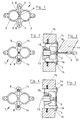
- the driver 1 consists essentially of two annular spring elements 2 and 3 in one plane symmetrical to the axis of symmetry S and side by side are arranged and a continuous at the transition point Have opening 4, the two prism-shaped workpiece receptacles 5 define.
- the clamping force on the Workpiece 6 only by the spring force of the two generated annular spring elements, this clamping force from the dimensions, i.e. Diameter, thickness and shape of the Driver and depends on the material.
- spring steel is used.
- the dimension of Workpiece prisms is, of course, by the Determine the diameter of the workpieces and adjust them accordingly.
- the driver In the direction of the axis of symmetry S, or the tips of the Workpiece holders, the driver has two elongated Openings 7, the outside each a prism-shaped end 8 have the, see Figure 2, the inclusion of appropriately shaped, prismatic bolts 14 on Serve opening mechanism of the cylindrical grinding machine. By the spreading of the bolts becomes the spring when taking up also spread, see Figure 4, around the workpiece to be recorded or removed.
- FIG. 3 schematically shows the one relevant to the invention Part of the cylindrical grinding machine indicated and you can see that Workpiece 6, for example a nozzle needle for the Injection technology, which lies between two fixed tips 9 and 10 is stored and processed by a grinding tool 11 becomes.
- the driver 1 is by one of the two bolts 14th of the opening mechanism 13 via the drive of the Cylindrical grinding machine driven.
- the driven opening mechanism contains two bolts 14, which are radially adjustable up to a fixed stop, whereby these bolts are acted upon by a sliding cone 15, which is pulled out in the position of Figure 3 such that the bolts are under the force of a spring 16 and in do not exert any force on the driver in this position, while in the position according to FIG. 5 the cone 15 is inserted and the two bolts counter to the force the spring 16 and thus the driver, or its Workpiece prisms, spreads.
- the bolts at their prismatic ends Notches 18 on.
- Such driver plates have been manufactured and used by the applicant for years and are designed such that a floating and backlash-free connection is guaranteed.
- By appropriate Shape of the connecting elements of the driver plate is with the driver a torsionally rigid, radial and axial compliant connection made that the Drive torque from the machine to the driver transmits almost without lateral force.
- merging the torsional stiffness can be the several driving plates Requirements are adjusted accordingly.
- the description shows that the exact Design of both the workpiece holder prisms 5 and also the prism-shaped ends 8 the center axis of the two workpiece prisms with the tip axis matches and that it is possible the carrier at right angles to the workpiece axis and on the Lower workpiece.
- the whole carrier is on one level arranged so that no twisting and no bending moment is transferred to the workpiece.
- the clamping force, or the driving force is only by the Dimension and material of the driver determined so that the clamping force by changing the Material thickness easily and without changing any other Properties can be adapted to the respective requirements can.
- the driver is in The present embodiment is made of spring steel, however, another material can also be used.
- the annular spring elements in the the present exemplary embodiments have a circular design, but it is conceivable to use differently designed spring elements use, for example triangular or polygonal annular spring elements, which at their transition point continuous opening with the prism-shaped workpiece holders exhibit.
- a differently designed contact zone can be considered, e.g. Form fit or multiple contact points, e.g. three.
- the invention was based on a cylindrical grinding machine explained, but the driving device according to Invention also for other machine tools such as Precision lathes or machines are used.
Landscapes
- Engineering & Computer Science (AREA)
- Mechanical Engineering (AREA)
- Grinding Of Cylindrical And Plane Surfaces (AREA)
- Gripping On Spindles (AREA)
- Constituent Portions Of Griding Lathes, Driving, Sensing And Control (AREA)
- Jigs For Machine Tools (AREA)
- Turning (AREA)
- Grinding And Polishing Of Tertiary Curved Surfaces And Surfaces With Complex Shapes (AREA)
- Portable Nailing Machines And Staplers (AREA)
- Electrical Discharge Machining, Electrochemical Machining, And Combined Machining (AREA)
Description
- Verspannen des Werkstücks durch die Klemmkraft des Mitnehmers auf dem Werkstück,
- grosse umlaufende Masse des Mitnehmers im Verhältnis zur Steifigkeit des Werkstücks,
- die Kraftübertragung von der Maschine auf den Mitnehmer erzeugt eine zu hohe Querkraft im Verhältnis zur Steifigkeit des Werkstücks und die geometrischen Abmessungen beschränken die bearbeitbare Länge des Werkstücks.
- Figur 1
- zeigt in einer Aufsicht den Mitnehmer der erfindungsgemässen Mitnahmevorrichtung,
- Figur 2
- zeigt den auf dem Werkstück geklemmten Mitnehmer,
- Figur 3
- zeigt in einer schematischen Darstellung und im Schnitt den Mitnehmer mit dem Werkstück bei der Bearbeitung,
- die Figuren 4 und 5
- zeigen den Mitnehmer und die Rundschleifmaschine in geöffneter Stellung,
- die Figuren 6 - 10
- zeigen eine Ausführungsvariante zu den Figuren 1 - 5, wobei der Mitnehmer auf einer Mitnehmerplatte befestigt ist.
Claims (6)
- Mitnahmevorrichtung für eine Werkzeugmaschine, insbesondere Rundschleif- oder Drehmaschine, bei der das Werkstück (6) zwischen zwei ortsfesten Spitzen (9, 10) angetrieben ist, mit einer angetriebenen Einrichtung (13) zur abnehmbaren Befestigung eines Mitnehmers, der ausgebildet ist, das Werkstück mittels Federkraft zu halten und zu drehen, wobei der Mitnehmer (1) zwei symmetrisch nebeneinander angeordnete, ringförmige Federelemente (2, 3) enthält, die an der Uebergangsstelle zwischen den beiden Federelementen eine durchgehende Oeffnung (4) aufweisen, die zwei prismenförmige Werkstückaufnahmen (5) bildet, dadurch gekennzeichnet, dass der Mitnehmer (1) in der Achse der Spitzen der prismenförmigen Werkstückaufnahmen (5) je eine Längsöffnung (7) mit einem prismenförmigen Ende (8) zur Aufnahme je eines entsprechend geformten Bolzens (14) an der angetriebenen Einrichtung (13) der Werkzeugmaschine zum Spreizen der Federelemente aufweist.
- Mitnahmevorrichtung nach Anspruch 1, dadurch gekennzeichnet, dass die ringförmigen Federelemente (2, 3) rund, drei- oder mehreckig ausgebildet sind.
- Mitnahmevorrichtung nach Anspruch 1 oder 2, dadurch gekennzeichnet, dass die beiden Bolzen (14) mittels einem verschiebbaren Konus (15) spreizbar sind.
- Mitnahmevorrichtung nach einem der Ansprüche 1 bis 3, dadurch gekennzeichnet, dass der Mitnehmer (1) auf einer Mitnehmerplatte (17) befestigt ist.
- Verwendung der Mitnahmevorrichtung nach Anspruch 1 an einer Werkzeugmaschine, dadurch gekennzeichnet, dass die Werkzeugmaschine eine Einrichtung aufweist, die ausgebildet ist, beim Stückwechsel in die Werkstückzone einzudringen.
- Verwendung der Mitnahmevorrichtung nach Anspruch 1, dadurch gekennzeichnet, dass der Mitnehmer ausserhalb des Arbeitsbereichs der Werkzeugmaschine auf das Werkstück geklemmt und dann zusammen mit diesem geladen und entladen wird.
Priority Applications (6)
| Application Number | Priority Date | Filing Date | Title |
|---|---|---|---|
| AT98810679T ATE210001T1 (de) | 1998-07-15 | 1998-07-15 | Mitnahmevorrichtung für eine werkzeugmaschine |
| ES98810679T ES2167860T3 (es) | 1998-07-15 | 1998-07-15 | Dispositivo de arrastre para una maquina herramienta. |
| DE59802339T DE59802339D1 (de) | 1998-07-15 | 1998-07-15 | Mitnahmevorrichtung für eine Werkzeugmaschine |
| EP98810679A EP0972613B1 (de) | 1998-07-15 | 1998-07-15 | Mitnahmevorrichtung für eine Werkzeugmaschine |
| US09/347,642 US6439974B1 (en) | 1998-07-15 | 1999-07-06 | Workpiece holder for a machine tool |
| JP20205299A JP4256029B2 (ja) | 1998-07-15 | 1999-07-15 | 工作機械の駆動装置 |
Applications Claiming Priority (1)
| Application Number | Priority Date | Filing Date | Title |
|---|---|---|---|
| EP98810679A EP0972613B1 (de) | 1998-07-15 | 1998-07-15 | Mitnahmevorrichtung für eine Werkzeugmaschine |
Publications (2)
| Publication Number | Publication Date |
|---|---|
| EP0972613A1 EP0972613A1 (de) | 2000-01-19 |
| EP0972613B1 true EP0972613B1 (de) | 2001-12-05 |
Family
ID=8236196
Family Applications (1)
| Application Number | Title | Priority Date | Filing Date |
|---|---|---|---|
| EP98810679A Expired - Lifetime EP0972613B1 (de) | 1998-07-15 | 1998-07-15 | Mitnahmevorrichtung für eine Werkzeugmaschine |
Country Status (6)
| Country | Link |
|---|---|
| US (1) | US6439974B1 (de) |
| EP (1) | EP0972613B1 (de) |
| JP (1) | JP4256029B2 (de) |
| AT (1) | ATE210001T1 (de) |
| DE (1) | DE59802339D1 (de) |
| ES (1) | ES2167860T3 (de) |
Families Citing this family (11)
| Publication number | Priority date | Publication date | Assignee | Title |
|---|---|---|---|---|
| CN100450678C (zh) * | 2007-07-20 | 2009-01-14 | 潘旭华 | 一种轴类零件加工用活动顶尖架 |
| IL196572A (en) * | 2008-02-04 | 2013-02-28 | Erowa Ag | Workpiece clamping fixture |
| CN101920464B (zh) * | 2009-06-10 | 2013-06-05 | 鸿富锦精密工业(深圳)有限公司 | 固定装置 |
| CN101607326B (zh) * | 2009-06-29 | 2011-01-26 | 浙江通力重型齿轮股份有限公司 | 用于加工齿轮轴的定位装置 |
| JP5345712B2 (ja) * | 2012-01-20 | 2013-11-20 | 鉅威自動化股▲分▼有限公司 | マイクロドリル研磨機の締め付け装置 |
| CN102632414B (zh) * | 2012-04-28 | 2013-11-27 | 苏州市达圣机械有限公司 | 一种导向基座表面加工的专用夹具 |
| CN105834910A (zh) * | 2016-05-30 | 2016-08-10 | 苏州微米光学科技有限公司 | 一种玻璃柱研磨装置的减震型研磨夹具 |
| CN108015592B (zh) * | 2017-12-08 | 2019-05-31 | 梧州奥卡光学仪器有限公司 | 转盘内孔车夹具 |
| CN109500412B (zh) * | 2018-12-13 | 2022-09-06 | 株洲易力达机电有限公司 | 一种复合式精密硬质合金活动顶尖及其使用方法 |
| CN112935870B (zh) * | 2021-02-01 | 2022-07-15 | 台州市东部数控设备有限公司 | 一种轴类零件用双主轴加工机床的夹持系统 |
| CN115555949B (zh) * | 2022-09-21 | 2024-12-17 | 安徽裕河新材料有限公司 | 一种生产发泡聚苯乙烯板的设备及生产方法 |
Family Cites Families (10)
| Publication number | Priority date | Publication date | Assignee | Title |
|---|---|---|---|---|
| US2693631A (en) * | 1951-11-30 | 1954-11-09 | Hamilton Watch Co | Floating chuck |
| CH340426A (fr) * | 1958-03-21 | 1959-08-15 | Mipsa Sa | Dispositif d'entraînement pour pièces fixées entre pointes sur une machine-outil |
| GB1109277A (en) * | 1965-09-13 | 1968-04-10 | Mikromat Dresden Betrieb | Improvements in and relating to grinding machines |
| US3855734A (en) * | 1973-03-28 | 1974-12-24 | Warner Swasey Co | Grinding machine with workpiece locator assembly |
| US4337599A (en) * | 1979-04-03 | 1982-07-06 | Toyoda Koki Kabushiki Kaisha | Method of shoulder grinding |
| CH663374A5 (en) * | 1984-07-10 | 1987-12-15 | Studer Ag Fritz | Work-driving unit for driving workpieces mounted between centres |
| DE3446138A1 (de) * | 1984-12-18 | 1986-06-19 | Fortuna-Werke Maschinenfabrik Gmbh, 7000 Stuttgart | Verfahren zur bestimmung der position eines werkstueckes in einer nc-gesteuerten maschine sowie eine nc-gesteuerte maschine zur durchfuehrung eines solchen verfahrens |
| JP2861715B2 (ja) * | 1993-02-18 | 1999-02-24 | 信越半導体株式会社 | インゴット円筒研削機における空回転防止装置 |
| JP3158760B2 (ja) * | 1993-02-26 | 2001-04-23 | 豊田工機株式会社 | 研削方法 |
| EP0782898B1 (de) * | 1996-01-08 | 2001-11-28 | Forkardt Schweiz AG | Verfahren zum Befestigen eines Spannaufsatzes auf einem Werkstück und Vorrichtung zu seiner Durchführung |
-
1998
- 1998-07-15 AT AT98810679T patent/ATE210001T1/de not_active IP Right Cessation
- 1998-07-15 DE DE59802339T patent/DE59802339D1/de not_active Expired - Lifetime
- 1998-07-15 ES ES98810679T patent/ES2167860T3/es not_active Expired - Lifetime
- 1998-07-15 EP EP98810679A patent/EP0972613B1/de not_active Expired - Lifetime
-
1999
- 1999-07-06 US US09/347,642 patent/US6439974B1/en not_active Expired - Lifetime
- 1999-07-15 JP JP20205299A patent/JP4256029B2/ja not_active Expired - Lifetime
Also Published As
| Publication number | Publication date |
|---|---|
| DE59802339D1 (de) | 2002-01-17 |
| ES2167860T3 (es) | 2002-05-16 |
| US6439974B1 (en) | 2002-08-27 |
| EP0972613A1 (de) | 2000-01-19 |
| JP2000052172A (ja) | 2000-02-22 |
| JP4256029B2 (ja) | 2009-04-22 |
| ATE210001T1 (de) | 2001-12-15 |
Similar Documents
| Publication | Publication Date | Title |
|---|---|---|
| EP0216796B1 (de) | Werkzeughalter od.dgl. | |
| EP1184113B1 (de) | Spannvorrichtung für einen Hohlschaft | |
| EP2114599B1 (de) | Ausgewuchtetes ausbohrwerkzeug mit klemmeinrichtung | |
| EP0972613B1 (de) | Mitnahmevorrichtung für eine Werkzeugmaschine | |
| WO1990009253A1 (de) | Kupplung zur lösbaren fixierung von bauteilen an entsprechenden trägerteilen | |
| DE2744410A1 (de) | 4-backen-spannfutter fuer ein werkstueck | |
| EP1961507A2 (de) | Spannvorrichtung | |
| DE3041650C2 (de) | Rollkupplungsfutter | |
| DE4309321A1 (de) | Anordnung zur zentrierten und axial fixierten Aufnahme eines rotierenden Körpers und zugehöriger Adapter | |
| EP2747922A1 (de) | Vorrichtung und verfahren zum spannen eines bauteils an einem rotierenden maschinenteil | |
| DE19920763B4 (de) | Zangenbolzenfutter | |
| EP1768808B1 (de) | Werkzeugadapter | |
| CH671718A5 (de) | ||
| EP3456448B1 (de) | Kupplungsvorrichtung | |
| EP3093088A1 (de) | Werkstückspannvorrichtung mit stirnseitenmitnehmer | |
| DE3603301A1 (de) | Spannvorrichtung fuer werkstuecke oder werkzeuge mit einer im umfang veraenderbaren spannhuelse | |
| CH668723A5 (de) | Revolverkopf fuer eine drehmaschine und hierzu passende werkzeughalter. | |
| EP2219811B1 (de) | Vorrichtung zum festspannen eines werkstückträgers an einem an einer bearbeitungsmaschine fixierbaren spannfutter | |
| EP3165310A1 (de) | Spannvorrichtung | |
| EP3165309B1 (de) | Spannvorrichtung | |
| DE20319597U1 (de) | Werkzeughalter-System | |
| EP4035811A1 (de) | Spannmittel und reduzierring hierfür | |
| EP1259350A1 (de) | Reibwerkzeug mit führungsschaft | |
| DE3410563C2 (de) | Spannvorrichtung für Werkzeuge od.dgl. | |
| DE102014114445A1 (de) | Spannfutter |
Legal Events
| Date | Code | Title | Description |
|---|---|---|---|
| PUAI | Public reference made under article 153(3) epc to a published international application that has entered the european phase |
Free format text: ORIGINAL CODE: 0009012 |
|
| AK | Designated contracting states |
Kind code of ref document: A1 Designated state(s): AT CH DE ES FR GB GR IT LI |
|
| AX | Request for extension of the european patent |
Free format text: AL;LT;LV;MK;RO;SI |
|
| 17P | Request for examination filed |
Effective date: 19991227 |
|
| 17Q | First examination report despatched |
Effective date: 20000808 |
|
| AKX | Designation fees paid |
Free format text: AT CH DE ES FR GB GR IT LI |
|
| GRAG | Despatch of communication of intention to grant |
Free format text: ORIGINAL CODE: EPIDOS AGRA |
|
| GRAG | Despatch of communication of intention to grant |
Free format text: ORIGINAL CODE: EPIDOS AGRA |
|
| GRAH | Despatch of communication of intention to grant a patent |
Free format text: ORIGINAL CODE: EPIDOS IGRA |
|
| GRAH | Despatch of communication of intention to grant a patent |
Free format text: ORIGINAL CODE: EPIDOS IGRA |
|
| GRAA | (expected) grant |
Free format text: ORIGINAL CODE: 0009210 |
|
| AK | Designated contracting states |
Kind code of ref document: B1 Designated state(s): AT CH DE ES FR GB GR IT LI |
|
| PG25 | Lapsed in a contracting state [announced via postgrant information from national office to epo] |
Ref country code: GR Free format text: LAPSE BECAUSE OF FAILURE TO SUBMIT A TRANSLATION OF THE DESCRIPTION OR TO PAY THE FEE WITHIN THE PRESCRIBED TIME-LIMIT Effective date: 20011205 |
|
| REF | Corresponds to: |
Ref document number: 210001 Country of ref document: AT Date of ref document: 20011215 Kind code of ref document: T |
|
| REG | Reference to a national code |
Ref country code: CH Ref legal event code: NV Representative=s name: AMMANN PATENTANWAELTE AG BERN Ref country code: CH Ref legal event code: EP |
|
| REG | Reference to a national code |
Ref country code: GB Ref legal event code: IF02 |
|
| REF | Corresponds to: |
Ref document number: 59802339 Country of ref document: DE Date of ref document: 20020117 |
|
| GBT | Gb: translation of ep patent filed (gb section 77(6)(a)/1977) |
Effective date: 20020204 |
|
| ET | Fr: translation filed | ||
| REG | Reference to a national code |
Ref country code: ES Ref legal event code: FG2A Ref document number: 2167860 Country of ref document: ES Kind code of ref document: T3 |
|
| REG | Reference to a national code |
Ref country code: GR Ref legal event code: EP Ref document number: 20020400339 Country of ref document: GR |
|
| PG25 | Lapsed in a contracting state [announced via postgrant information from national office to epo] |
Ref country code: AT Free format text: LAPSE BECAUSE OF NON-PAYMENT OF DUE FEES Effective date: 20020715 |
|
| PG25 | Lapsed in a contracting state [announced via postgrant information from national office to epo] |
Ref country code: ES Free format text: LAPSE BECAUSE OF NON-PAYMENT OF DUE FEES Effective date: 20020716 |
|
| PLBE | No opposition filed within time limit |
Free format text: ORIGINAL CODE: 0009261 |
|
| STAA | Information on the status of an ep patent application or granted ep patent |
Free format text: STATUS: NO OPPOSITION FILED WITHIN TIME LIMIT |
|
| 26N | No opposition filed | ||
| REG | Reference to a national code |
Ref country code: ES Ref legal event code: FD2A Effective date: 20030811 |
|
| REG | Reference to a national code |
Ref country code: FR Ref legal event code: PLFP Year of fee payment: 19 |
|
| REG | Reference to a national code |
Ref country code: FR Ref legal event code: PLFP Year of fee payment: 20 |
|
| PGFP | Annual fee paid to national office [announced via postgrant information from national office to epo] |
Ref country code: IT Payment date: 20170728 Year of fee payment: 20 Ref country code: GB Payment date: 20170719 Year of fee payment: 20 Ref country code: CH Payment date: 20170720 Year of fee payment: 20 Ref country code: FR Payment date: 20170724 Year of fee payment: 20 Ref country code: DE Payment date: 20170724 Year of fee payment: 20 |
|
| REG | Reference to a national code |
Ref country code: DE Ref legal event code: R071 Ref document number: 59802339 Country of ref document: DE |
|
| REG | Reference to a national code |
Ref country code: CH Ref legal event code: PL |
|
| REG | Reference to a national code |
Ref country code: GB Ref legal event code: PE20 Expiry date: 20180714 |
|
| PG25 | Lapsed in a contracting state [announced via postgrant information from national office to epo] |
Ref country code: GB Free format text: LAPSE BECAUSE OF EXPIRATION OF PROTECTION Effective date: 20180714 |