EP0971474B1 - Motor boot for a circuit board - Google Patents
Motor boot for a circuit board Download PDFInfo
- Publication number
- EP0971474B1 EP0971474B1 EP99305391A EP99305391A EP0971474B1 EP 0971474 B1 EP0971474 B1 EP 0971474B1 EP 99305391 A EP99305391 A EP 99305391A EP 99305391 A EP99305391 A EP 99305391A EP 0971474 B1 EP0971474 B1 EP 0971474B1
- Authority
- EP
- European Patent Office
- Prior art keywords
- motor
- boot
- connector
- circuit board
- housing
- Prior art date
- Legal status (The legal status is an assumption and is not a legal conclusion. Google has not performed a legal analysis and makes no representation as to the accuracy of the status listed.)
- Expired - Lifetime
Links
Images

Classifications
-
- H—ELECTRICITY
- H05—ELECTRIC TECHNIQUES NOT OTHERWISE PROVIDED FOR
- H05K—PRINTED CIRCUITS; CASINGS OR CONSTRUCTIONAL DETAILS OF ELECTRIC APPARATUS; MANUFACTURE OF ASSEMBLAGES OF ELECTRICAL COMPONENTS
- H05K3/00—Apparatus or processes for manufacturing printed circuits
- H05K3/30—Assembling printed circuits with electric components, e.g. with resistor
- H05K3/32—Assembling printed circuits with electric components, e.g. with resistor electrically connecting electric components or wires to printed circuits
-
- H—ELECTRICITY
- H02—GENERATION; CONVERSION OR DISTRIBUTION OF ELECTRIC POWER
- H02K—DYNAMO-ELECTRIC MACHINES
- H02K5/00—Casings; Enclosures; Supports
-
- G—PHYSICS
- G08—SIGNALLING
- G08B—SIGNALLING OR CALLING SYSTEMS; ORDER TELEGRAPHS; ALARM SYSTEMS
- G08B6/00—Tactile signalling systems, e.g. personal calling systems
-
- H—ELECTRICITY
- H02—GENERATION; CONVERSION OR DISTRIBUTION OF ELECTRIC POWER
- H02K—DYNAMO-ELECTRIC MACHINES
- H02K5/00—Casings; Enclosures; Supports
- H02K5/04—Casings or enclosures characterised by the shape, form or construction thereof
- H02K5/22—Auxiliary parts of casings not covered by groups H02K5/06-H02K5/20, e.g. shaped to form connection boxes or terminal boxes
- H02K5/225—Terminal boxes or connection arrangements
-
- H—ELECTRICITY
- H02—GENERATION; CONVERSION OR DISTRIBUTION OF ELECTRIC POWER
- H02K—DYNAMO-ELECTRIC MACHINES
- H02K5/00—Casings; Enclosures; Supports
- H02K5/24—Casings; Enclosures; Supports specially adapted for suppression or reduction of noise or vibrations
-
- H—ELECTRICITY
- H02—GENERATION; CONVERSION OR DISTRIBUTION OF ELECTRIC POWER
- H02K—DYNAMO-ELECTRIC MACHINES
- H02K7/00—Arrangements for handling mechanical energy structurally associated with dynamo-electric machines, e.g. structural association with mechanical driving motors or auxiliary dynamo-electric machines
- H02K7/06—Means for converting reciprocating motion into rotary motion or vice versa
- H02K7/065—Electromechanical oscillators; Vibrating magnetic drives
-
- H—ELECTRICITY
- H02—GENERATION; CONVERSION OR DISTRIBUTION OF ELECTRIC POWER
- H02K—DYNAMO-ELECTRIC MACHINES
- H02K2211/00—Specific aspects not provided for in the other groups of this subclass relating to measuring or protective devices or electric components
- H02K2211/03—Machines characterised by circuit boards, e.g. pcb
-
- H—ELECTRICITY
- H05—ELECTRIC TECHNIQUES NOT OTHERWISE PROVIDED FOR
- H05K—PRINTED CIRCUITS; CASINGS OR CONSTRUCTIONAL DETAILS OF ELECTRIC APPARATUS; MANUFACTURE OF ASSEMBLAGES OF ELECTRICAL COMPONENTS
- H05K3/00—Apparatus or processes for manufacturing printed circuits
- H05K3/30—Assembling printed circuits with electric components, e.g. with resistor
- H05K3/301—Assembling printed circuits with electric components, e.g. with resistor by means of a mounting structure
Definitions
- the present invention relates to motor boots and, in particular, the present invention relates to a motor boot for mechanically and electrically connecting a motor to a circuit board.
- Typical motor boots and the associated motors take a great number of steps to install, which usually consist of the following.
- PCB Printed Circuit Board
- the boot and motor are mounted in an electronic device, such as a mobile phone or pager.
- This type of motor boot is difficult to install, labor intensive during installation, and makes a large "footprint" on the circuit board, thereby taking up precious space within the electronic device.
- the connection method of these motor boots are soldered to the PCB thereby causing difficult rework procedures in manufacturing.
- US patent 5,657,205 discloses a mounting structure for holding a vibration generating motor and efficiently conveying the vibrations of the motor to a circuit board.
- the structure includes a motor holding section, a fixing section and a tongue piece contacting the inner surface of the circuit board.
- the holding section has a cylindrical inner surface for holding the motor.
- the fixing section is attached right above the holding section with tongue pieces on the side and is shaped to fit and securely hold the structure to a hole on the circuit board. The structure is not easily removed from the circuit board once it is mounted.
- European patent application EP 0 817 551 A1 discloses a motor mounting bracket for mounting a motor on a printed circuit board.
- the bracket includes an elongated housing having a receptacle for holding the motor.
- the housing further includes a pair of elongated conductive contacts mounted on the housing across from each other with each contact adapted to be engaged to the motor at one end and to the circuit board at the other end.
- the present invention eliminates the above difficulties and disadvantages by providing a motor boot for mechanically and electrically connecting a motor to a circuit board having an electrical contact and the motor having an electrical pad and a nob disposed thereon, the motor boot comprising:
- the connector is integrally formed with the housing thereby making the motor boot of one piece construction.
- the connector is slidably received and releasbly secured within the slot by interference fit.
- FIG 1 Shown in FIG 1 is a motor boot 10 for mechanically and electrically connecting a motor 40 to a circuit board 18.
- the motor boot 10 of the present invention is preferably constructed of SANTOPRENE 101-55, having a 55 shore A durometer of hardness and manufactured by Advanced Elastomer Systems of the United States; SANTOPRENE 101-45 having a 45 shore A durometer of hardness and manufactured by Advanced Elastomer Systems of the United States; LIM 6050, having a 55 Shore A durometer of hardness and manufactured by General Electric Company of the United States; LIM 6061, having a 60 Shore A durometer of hardness and manufactured by General Electric Company of the United States; or LIM 6071, having a 70 Shore A durometer of hardness and manufactured by General Electric Company of the United States. It is understood, however, that the motor boot 10 could also be constructed of other non-electrically conductive elastomers such as silicon rubber and that the above list is exemplary rather than limiting.
- the motor 40 has a surface mounted, electrical pad 48 disposed thereon for receiving an electrical signal for operation of the motor 40, a cylinder 42 that contains inductive windings of the motor 40, and a nob 50 disposed at one end of the cylinder 42.
- the motor 40 is preferably manufactured by the Namiki Company of Japan and further includes a rotating shaft 44 that extends outward from the cylinder 42 and a counter weight 46 secured to the shaft 44.
- Common mobile devices in which the circuit board 18, boot 10, and motor 40 are typically installed in, but that are not limited to, are pagers, mobile telephones, and other electronic devices.
- the motor boot 10 further includes a vibrational damping housing, as shown in FIGS 1, 2, 4, 5, and 6, which is constructed of the elastomeric material as described above.
- the housing is U-shaped 32 and includes a first support leg 12 with a contact surface 16 and a slot 14 disposed therein.
- a second support leg 22 is spaced apart from the first support leg 12 and includes a brace surface 24. The first and second legs support the boot 10 as it is compression fit against the circuit board 18.
- a base 34 is integrally formed between and spaces apart the first and second support legs.
- a receptacle for slidably receiving and releasably securing the motor 40 therein by interference fit, allowing for the motor 40 to be easily installed and uninstalled in the boot 10.
- the receptacle is preferably cylindrical in shape to receive the cylinder 42 of the motor 40 but could also be other configurations, such as rectangular or conical, depending upon the shape of the motor 40.
- the receptacle includes a cut-out 30 that is in fluid flow communication with the slot 14 for receiving the electrical pad 48 of the motor 40 therein, and a port 36 for receiving the nob 50 of the motor 40 when the cylinder 42 is inserted into the receptacle. As is best shown in FIGS 4 and 6, the receptacle longitudinally extends through the housing.
- a connector 26, as shown in FIGS 1 and 2 is disposed in the slot 14 and contacts the electrical pad 48 of the motor 40 and the contact 20 when the motor boot 10 is connected to the circuit board 18, thereby creating electrical communication between the motor 40 and circuit board 18.
- the connector 26 is slidably received and releasably secured within the slot by interference fit. Therefore, just as the motor 40 is easily inserted into and removed from the receptacle because of the interference fit, so too is the connector 26 easily inserted into and removed from the slot 14 in this embodiment.
- the inference fit of the connector 26 allows for it to be easily replaced in a manufacturing setting, or in the field, if a connector 26 of differing height is needed for varying clearances within different devices in which the boot 10 is installed.
- the connector 26 is constructed of an electrically conductive elastomeric material, which is preferably a STAX elastomeric connector manufactured by Thomas & Betts Corporation of Memphis, Tennessee. Because the connector 26 is elastomeric, it provides for absorption of mechanical energy emitted by the motor 40 such as vibrational damping and the transfer of electrical energy from, or to, the circuit board 18.
- the motor boot 10 is connected to the circuit board 18 by compression force being applied to the housing by a wall of the device such that the connector 26 abuts the contact 20.
- the brace surface 24 of the second support leg 22 is preferably compressed against the circuit board 18 as the integrally formed housing is compressed by a wall of the device.
- the connector 26 abuts and is compressed against the contact 20 of the circuit board 18 thereby allowing electrical signals to pass through the connector 26 between the circuit board 18 and motor 40.
- the connector 26 is an electrically conductive elastomer, the connector 26 will compress when the housing is compressed into the device such that the contact surface 16 of the first support leg 12 will come in contact 20 with the circuit board 18 thereby giving the motor boot 10 a low height profile in the device.
- the connector 26 is integrally formed with the housing thereby making the motor boot 10 of one piece construction. This is easily accomplished in the present invention because both the housing and connector 26 are constructed of an elastomeric material.
- the slot 14 is doped with the electrically conductive elastomeric material that makes up the connector 26 as described above.
- an elastomeric adhesive can be placed in the slot 14 such that the connector 26 becomes chemically bonded to the elastomeric material of the housing. It is possible to insert mold the connector into the boot, therefore eliminating the need for adhesive.
Landscapes
- Engineering & Computer Science (AREA)
- Power Engineering (AREA)
- Physics & Mathematics (AREA)
- General Physics & Mathematics (AREA)
- Manufacturing & Machinery (AREA)
- Microelectronics & Electronic Packaging (AREA)
- Motor Or Generator Frames (AREA)
- Pharmaceuticals Containing Other Organic And Inorganic Compounds (AREA)
- Mounting Of Printed Circuit Boards And The Like (AREA)
- Structures For Mounting Electric Components On Printed Circuit Boards (AREA)
- Transplanting Machines (AREA)
- Control Of Throttle Valves Provided In The Intake System Or In The Exhaust System (AREA)
- Apparatuses For Generation Of Mechanical Vibrations (AREA)
- Insulation, Fastening Of Motor, Generator Windings (AREA)
Abstract
Description
- In general, the present invention relates to motor boots and, in particular, the present invention relates to a motor boot for mechanically and electrically connecting a motor to a circuit board.
- Typical motor boots and the associated motors take a great number of steps to install, which usually consist of the following. First, a motor is fitted with a boot. Second, motor lead wires are soldered to a Printed Circuit Board (PCB) for electrical operation of the motor. Next, the boot and motor are mounted in an electronic device, such as a mobile phone or pager. This type of motor boot is difficult to install, labor intensive during installation, and makes a large "footprint" on the circuit board, thereby taking up precious space within the electronic device. In addition, the connection method of these motor boots are soldered to the PCB thereby causing difficult rework procedures in manufacturing.
- US patent 5,657,205 discloses a mounting structure for holding a vibration generating motor and efficiently conveying the vibrations of the motor to a circuit board. The structure includes a motor holding section, a fixing section and a tongue piece contacting the inner surface of the circuit board. The holding section has a cylindrical inner surface for holding the motor. The fixing section is attached right above the holding section with tongue pieces on the side and is shaped to fit and securely hold the structure to a hole on the circuit board. The structure is not easily removed from the circuit board once it is mounted.
- European patent application EP 0 817 551 A1 discloses a motor mounting bracket for mounting a motor on a printed circuit board. The bracket includes an elongated housing having a receptacle for holding the motor. The housing further includes a pair of elongated conductive contacts mounted on the housing across from each other with each contact adapted to be engaged to the motor at one end and to the circuit board at the other end.
- The present invention eliminates the above difficulties and disadvantages by providing a motor boot for mechanically and electrically connecting a motor to a circuit board having an electrical contact and the motor having an electrical pad and a nob disposed thereon, the motor boot comprising:
- an elongated vibrational damping housing constructed of elastomeric material, U-shaped, and including a first support leg with a slot disposed therein, a second support leg spaced apart from the first support leg, and a base integrally formed with the first and second support legs;
- a substantially enclosed cylindrical receptacle formed in the housing for slidably receiving and releasably securing the motor therein by interference fit, the receptacle including a cut-out in fluid flow communication with the slot for receiving the electrical pad of the motor therein, and a port for receiving the nob of the motor therein;
- a vibrational damping connector releasably disposed in the slot and contacting the electrical pad of the motor and the contact when the motor boot is connected to the circuit board, thereby creating electrical communication between the motor and circuit board, the connector being constructed of an electrically conductive elastomeric material; and wherein the motor boot is connected to the circuit board by compression force being applied to the housing such that the connector abuts the contact.
-
- In one embodiment, the connector is integrally formed with the housing thereby making the motor boot of one piece construction. In yet another embodiment, the connector is slidably received and releasbly secured within the slot by interference fit.
-
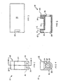
- FIG 1 is a perspective view of a motor boot of the present invention and associated motor.
- FIG 2 is an exploded view of the motor boot of the present invention and associated motor.
- FIG 3 is a plan view of a circuit board.
- FIG 4 is a side elevational view of the motor boot of the present invention.
- FIG 5 is a plan view of the motor boot of the present invention.
- FIG 6 is cross sectional view of the motor boot of the present invention taken along sight line A-A of FIG 5.
-
- The above features, aspects, and advantages of the present invention will now be discussed in the following detailed description and appended claims, which are to be considered in conjunction with the accompanying drawings in which identical reference characters designate like elements throughout the views. Shown in FIG 1 is a
motor boot 10 for mechanically and electrically connecting amotor 40 to acircuit board 18. - The
motor boot 10 of the present invention is preferably constructed of SANTOPRENE 101-55, having a 55 shore A durometer of hardness and manufactured by Advanced Elastomer Systems of the United States; SANTOPRENE 101-45 having a 45 shore A durometer of hardness and manufactured by Advanced Elastomer Systems of the United States; LIM 6050, having a 55 Shore A durometer of hardness and manufactured by General Electric Company of the United States; LIM 6061, having a 60 Shore A durometer of hardness and manufactured by General Electric Company of the United States; or LIM 6071, having a 70 Shore A durometer of hardness and manufactured by General Electric Company of the United States. It is understood, however, that themotor boot 10 could also be constructed of other non-electrically conductive elastomers such as silicon rubber and that the above list is exemplary rather than limiting. - As shown in FIG 2, the
motor 40 has a surface mounted, electrical pad 48 disposed thereon for receiving an electrical signal for operation of themotor 40, acylinder 42 that contains inductive windings of themotor 40, and a nob 50 disposed at one end of thecylinder 42. Themotor 40 is preferably manufactured by the Namiki Company of Japan and further includes a rotatingshaft 44 that extends outward from thecylinder 42 and acounter weight 46 secured to theshaft 44. Common mobile devices in which thecircuit board 18,boot 10, andmotor 40 are typically installed in, but that are not limited to, are pagers, mobile telephones, and other electronic devices. - The
motor boot 10 further includes a vibrational damping housing, as shown in FIGS 1, 2, 4, 5, and 6, which is constructed of the elastomeric material as described above. The housing is U-shaped 32 and includes afirst support leg 12 with acontact surface 16 and aslot 14 disposed therein. Asecond support leg 22 is spaced apart from thefirst support leg 12 and includes abrace surface 24. The first and second legs support theboot 10 as it is compression fit against thecircuit board 18. Abase 34 is integrally formed between and spaces apart the first and second support legs. - Formed in the housing is a receptacle for slidably receiving and releasably securing the
motor 40 therein by interference fit, allowing for themotor 40 to be easily installed and uninstalled in theboot 10. The receptacle is preferably cylindrical in shape to receive thecylinder 42 of themotor 40 but could also be other configurations, such as rectangular or conical, depending upon the shape of themotor 40. The receptacle includes a cut-out 30 that is in fluid flow communication with theslot 14 for receiving the electrical pad 48 of themotor 40 therein, and aport 36 for receiving the nob 50 of themotor 40 when thecylinder 42 is inserted into the receptacle. As is best shown in FIGS 4 and 6, the receptacle longitudinally extends through the housing. - A
connector 26, as shown in FIGS 1 and 2, is disposed in theslot 14 and contacts the electrical pad 48 of themotor 40 and thecontact 20 when themotor boot 10 is connected to thecircuit board 18, thereby creating electrical communication between themotor 40 andcircuit board 18. In another embodiment of the present invention, theconnector 26 is slidably received and releasably secured within the slot by interference fit. Therefore, just as themotor 40 is easily inserted into and removed from the receptacle because of the interference fit, so too is theconnector 26 easily inserted into and removed from theslot 14 in this embodiment. The inference fit of theconnector 26 allows for it to be easily replaced in a manufacturing setting, or in the field, if aconnector 26 of differing height is needed for varying clearances within different devices in which theboot 10 is installed. This interchangeability prevents theentire motor boot 10 from being discarded when theboot 10 is used in a different device. Theconnector 26 is constructed of an electrically conductive elastomeric material, which is preferably a STAX elastomeric connector manufactured by Thomas & Betts Corporation of Memphis, Tennessee. Because theconnector 26 is elastomeric, it provides for absorption of mechanical energy emitted by themotor 40 such as vibrational damping and the transfer of electrical energy from, or to, thecircuit board 18. - During installation of the
motor boot 10 in the device, themotor boot 10 is connected to thecircuit board 18 by compression force being applied to the housing by a wall of the device such that theconnector 26 abuts thecontact 20. In particular, thebrace surface 24 of thesecond support leg 22 is preferably compressed against thecircuit board 18 as the integrally formed housing is compressed by a wall of the device. Moreover, theconnector 26 abuts and is compressed against thecontact 20 of thecircuit board 18 thereby allowing electrical signals to pass through theconnector 26 between thecircuit board 18 andmotor 40. Because thepresent connector 26 is an electrically conductive elastomer, theconnector 26 will compress when the housing is compressed into the device such that thecontact surface 16 of thefirst support leg 12 will come incontact 20 with thecircuit board 18 thereby giving the motor boot 10 a low height profile in the device. - In one embodiment of the present invention, the
connector 26 is integrally formed with the housing thereby making themotor boot 10 of one piece construction. This is easily accomplished in the present invention because both the housing andconnector 26 are constructed of an elastomeric material. During manufacturing of the housing, theslot 14 is doped with the electrically conductive elastomeric material that makes up theconnector 26 as described above. Alternatively, an elastomeric adhesive can be placed in theslot 14 such that theconnector 26 becomes chemically bonded to the elastomeric material of the housing. It is possible to insert mold the connector into the boot, therefore eliminating the need for adhesive. - The above description is to be considered exemplary, rather than limiting, and the true scope of the invention is that defined in the following claims.
Claims (5)
- A motor boot (10) for mechanically and electrically connecting a motor (40) to a circuit board (18) having an electrical contact (20) and the motor (40) having an electrical pad (48) and a nob (50) disposed thereon, the motor boot (10) comprising:wherein the motor boot (10) is connected to the circuit board (18) by compression force being applied to the housing (32) such that the connector (26) abuts the contact (20).an elongated vibrational damping housing (32) constructed of elastomeric material, U-shaped, and including a first support leg (12) with a slot (14) disposed therein, a second support leg (22) spaced apart from the first support leg (12), and a base integrally formed with the first and second support legs (12, 22);a substantially enclosed cylindrical receptacle formed in the housing (32) for slidably receiving and releasably securing the motor (40) therein by interference fit, the receptacle including a cut-out (30) in fluid flow communication with the slot (14) for receiving the electrical pad (48) of the motor (40) therein, and a port (36) for receiving the nob (50) of the motor (40) therein;a vibrational damping connector (26) releasably disposed in the slot (14) and contacting the electrical pad (48) of the motor (40) and the contact (20) when the motor boot (10) is connected to the circuit board (18), thereby creating electrical communication between the motor (40) and circuit board (18), the connector (26) being constructed of an electrically conductive elastomeric material; and
- The motor boot (10) of claim 1 wherein both the housing (32) and connector (26) are constructed of an elastomeric material for damping vibration of the motor (40).
- The motor boot (10) of claim or claim 2 wherein the connector (26) is disposed in the housing (32) via use of an adhesive.
- The motor boot (10) of any one of claims 1 to 3 wherein the connector (26) is slidably received and releasably secured within the slot (14) by interference fit.
- The motor boot (10) of any one of claims 1 to 4 wherein the connector (26) is integrally formed with the housing (32) thereby making the motor boot (10) of one piece construction.
Applications Claiming Priority (2)
| Application Number | Priority Date | Filing Date | Title |
|---|---|---|---|
| US113884 | 1998-07-10 | ||
| US09/113,884 US6227901B1 (en) | 1998-07-10 | 1998-07-10 | Motor boot for a circuit board |
Publications (2)
| Publication Number | Publication Date |
|---|---|
| EP0971474A1 EP0971474A1 (en) | 2000-01-12 |
| EP0971474B1 true EP0971474B1 (en) | 2005-10-19 |
Family
ID=22352104
Family Applications (1)
| Application Number | Title | Priority Date | Filing Date |
|---|---|---|---|
| EP99305391A Expired - Lifetime EP0971474B1 (en) | 1998-07-10 | 1999-07-07 | Motor boot for a circuit board |
Country Status (9)
| Country | Link |
|---|---|
| US (1) | US6227901B1 (en) |
| EP (1) | EP0971474B1 (en) |
| JP (1) | JP2000102206A (en) |
| KR (1) | KR20000011534A (en) |
| AT (1) | ATE307416T1 (en) |
| DE (1) | DE69927751T2 (en) |
| MY (1) | MY122321A (en) |
| SG (1) | SG97798A1 (en) |
| TW (1) | TW526631B (en) |
Families Citing this family (24)
| Publication number | Priority date | Publication date | Assignee | Title |
|---|---|---|---|---|
| JP2994358B1 (en) * | 1998-09-16 | 1999-12-27 | 静岡日本電気株式会社 | Vibration motor |
| DE10014227A1 (en) * | 2000-03-22 | 2001-09-27 | Bosch Gmbh Robert | Device for connecting components with different electrical potentials e.g. motor to clutch actuator control electronics for motor vehicle, has synthetic ring in opening in 1st component, and journal-shaped part of 2nd component |
| JP2001309004A (en) * | 2000-04-27 | 2001-11-02 | Matsushita Electric Ind Co Ltd | Portable electronic unit and small dc motor installed on the same through elastic member |
| US6254416B1 (en) * | 2000-05-18 | 2001-07-03 | Molex Incorporated | Vibrator motor holder |
| KR100404332B1 (en) * | 2000-11-17 | 2003-11-01 | 캐리어 주식회사 | Motor Terminal With Fusing Partially |
| US6835071B2 (en) | 2001-07-18 | 2004-12-28 | Tyco Electronics Corporation | Elastomeric connector interconnecting flexible circuits and circuit board and method of manufacturing the same |
| US7152695B2 (en) | 2002-09-20 | 2006-12-26 | Snap-On Incorporated | Power tool with air seal and vibration dampener |
| DE10332167A1 (en) | 2003-07-15 | 2005-02-10 | Pwb-Ruhlatec Industrieprodukte Gmbh | Encoder system and method for mounting an encoder system |
| US6796811B1 (en) | 2003-07-31 | 2004-09-28 | Tyco Electronics Corporation | Connector with dedicated contact regions |
| US7119463B2 (en) * | 2003-07-31 | 2006-10-10 | Research In Motion Limited | Vibration motor boot |
| US20070020972A1 (en) * | 2005-07-21 | 2007-01-25 | Tyco Electronics Corporation | Elastomeric connectors and retention members for holding the same |
| US7326068B2 (en) * | 2005-07-26 | 2008-02-05 | Tyco Electronics Corporation | Elastomeric connector and retention member for holding the same |
| CN1881712B (en) * | 2006-05-07 | 2011-07-06 | 干方飞 | Electric connector of flat type vibration source |
| JP4882649B2 (en) * | 2006-10-03 | 2012-02-22 | 市光工業株式会社 | Motor module assembly |
| TWI394184B (en) * | 2008-06-18 | 2013-04-21 | Delta Electronics Inc | Integrated magnetic device |
| CN101609585A (en) * | 2008-06-20 | 2009-12-23 | 深圳富泰宏精密工业有限公司 | The vibrator structure of electronic installation |
| TWI452804B (en) * | 2008-08-15 | 2014-09-11 | Chi Mei Comm Systems Inc | Vibrator structure of electronic device |
| DE102009028391A1 (en) * | 2009-08-10 | 2011-02-17 | Robert Bosch Gmbh | connecting device |
| CN201629481U (en) * | 2010-02-05 | 2010-11-10 | 国基电子(上海)有限公司 | Electronic equipment |
| DE102011013827A1 (en) * | 2011-03-14 | 2012-09-20 | Maschinenfabrik Niehoff Gmbh & Co. Kg | Apparatus for continuous heat treatment of electrically conductive extrudate and arrangement of a sliding contact element |
| TWM468814U (en) * | 2013-08-28 | 2013-12-21 | Bellwether Electronic Corp | Connector tape and connector module thereof |
| EP2858183A3 (en) * | 2013-10-03 | 2015-06-17 | Yasaki Corporation | Connector joining structure |
| JP6744370B2 (en) * | 2018-08-10 | 2020-08-19 | 矢崎総業株式会社 | Board mount connector |
| CN115085449B (en) * | 2022-07-22 | 2022-11-15 | 常州市昊升电机股份有限公司 | Motor for vehicle three-way cooling valve and mounting method thereof |
Family Cites Families (26)
| Publication number | Priority date | Publication date | Assignee | Title |
|---|---|---|---|---|
| JPS5993155U (en) | 1982-12-15 | 1984-06-25 | シャープ株式会社 | Electronic equipment with solar cells |
| US4633110A (en) * | 1985-03-20 | 1986-12-30 | Rotron, Inc. | Motor with stator on printed circuit assembly |
| US4927368A (en) | 1986-10-13 | 1990-05-22 | Sharp Kabushiki Kaisha | Connector |
| EP0332560B1 (en) | 1988-03-11 | 1994-03-02 | International Business Machines Corporation | Elastomeric connectors for electronic packaging and testing |
| JPH0665788B2 (en) * | 1989-07-18 | 1994-08-24 | 住友ベークライト株式会社 | Sound insulation floor material |
| US5292259A (en) | 1990-04-12 | 1994-03-08 | Nokia Mobile Phones (U.K.) Limited | Electrical connector |
| US5319864A (en) * | 1992-03-06 | 1994-06-14 | Emerson Electric Co. | Printed circuit board carried inside a cam-operated timer |
| US5380212A (en) | 1992-08-14 | 1995-01-10 | Hewlett Packard Company | Conductive elastomeric interface for a pin grid array |
| US5504940A (en) | 1992-11-13 | 1996-04-02 | Motorola, Inc. | Shock isolation system having integral electrical interconnects |
| JP2564835Y2 (en) * | 1993-09-02 | 1998-03-11 | 松下電器産業株式会社 | Small motor |
| GB9321388D0 (en) | 1993-10-16 | 1993-12-08 | Nokia Mobile Phones Ltd | Vibration damping mounting |
| US5482473A (en) | 1994-05-09 | 1996-01-09 | Minimed Inc. | Flex circuit connector |
| FI96150C (en) | 1994-07-19 | 1996-05-10 | Nokia Telecommunications Oy | Temperature compensated combiner |
| JP2568050B2 (en) * | 1994-08-08 | 1996-12-25 | 静岡日本電気株式会社 | Motor holding mechanism |
| US5599193A (en) | 1994-08-23 | 1997-02-04 | Augat Inc. | Resilient electrical interconnect |
| JP2731732B2 (en) | 1994-11-10 | 1998-03-25 | 静岡日本電気株式会社 | Holding structure of vibration generating motor used for small electronic equipment |
| US5769657A (en) * | 1995-02-23 | 1998-06-23 | Makita Corporation | Attachment structure of battery pack to power-driven tools |
| JPH08261431A (en) | 1995-03-28 | 1996-10-11 | Kubota Corp | Method and device for estimating thickness of waste on incinerating zone in incinerator |
| US5707249A (en) * | 1996-02-12 | 1998-01-13 | Schneider Automation Inc. | Device holder attaching to a printed circuit board |
| US5879199A (en) * | 1996-02-29 | 1999-03-09 | Berg Technology, Inc. | Modular jack assembly and universal housing for use therein |
| US5749737A (en) | 1996-07-02 | 1998-05-12 | Molex Incorporated | Motor mounting bracket for PCB |
| JP2880963B2 (en) | 1996-08-09 | 1999-04-12 | 静岡日本電気株式会社 | Vibration motor holding structure |
| JPH1084649A (en) * | 1996-09-10 | 1998-03-31 | Optec Dai Ichi Denko Co Ltd | Cylindrical micro vibration motor with terminal bracket |
| JP3281268B2 (en) | 1996-09-25 | 2002-05-13 | 松下電器産業株式会社 | Small motor holding device for receiver |
| US5735697A (en) * | 1996-09-27 | 1998-04-07 | Itt Corporation | Surface mount connector |
| US5875562A (en) * | 1997-06-18 | 1999-03-02 | Fogarty; Shaun P. | Hand-held hair dryer with vibration and noise control |
-
1998
- 1998-07-10 US US09/113,884 patent/US6227901B1/en not_active Expired - Fee Related
-
1999
- 1999-06-25 SG SG9903552A patent/SG97798A1/en unknown
- 1999-07-07 DE DE69927751T patent/DE69927751T2/en not_active Expired - Fee Related
- 1999-07-07 AT AT99305391T patent/ATE307416T1/en not_active IP Right Cessation
- 1999-07-07 KR KR1019990027202A patent/KR20000011534A/en not_active Application Discontinuation
- 1999-07-07 EP EP99305391A patent/EP0971474B1/en not_active Expired - Lifetime
- 1999-07-08 TW TW088111589A patent/TW526631B/en not_active IP Right Cessation
- 1999-07-09 JP JP11195499A patent/JP2000102206A/en active Pending
- 1999-07-09 MY MYPI99002900A patent/MY122321A/en unknown
Also Published As
| Publication number | Publication date |
|---|---|
| ATE307416T1 (en) | 2005-11-15 |
| JP2000102206A (en) | 2000-04-07 |
| TW526631B (en) | 2003-04-01 |
| MY122321A (en) | 2006-03-31 |
| EP0971474A1 (en) | 2000-01-12 |
| DE69927751D1 (en) | 2006-03-02 |
| KR20000011534A (en) | 2000-02-25 |
| SG97798A1 (en) | 2003-08-20 |
| US6227901B1 (en) | 2001-05-08 |
| DE69927751T2 (en) | 2006-06-01 |
Similar Documents
| Publication | Publication Date | Title |
|---|---|---|
| EP0971474B1 (en) | Motor boot for a circuit board | |
| KR101060987B1 (en) | Small motor for vibration and its mounting member and portable electronic device provided with it | |
| US7619335B2 (en) | Vibration motor | |
| AU697830B2 (en) | Vibration-generating-motor mounting structure and its mounting method | |
| KR100367071B1 (en) | Cordless phone cradle connector | |
| WO2003038929A3 (en) | Battery system | |
| US7265465B2 (en) | Small-sized motor, small-sized vibration motor, and portable information device | |
| WO2002031401A2 (en) | Holder for electronic device, such as a microphone | |
| JP3281268B2 (en) | Small motor holding device for receiver | |
| WO2002064269A1 (en) | Small-sized vibrating motor | |
| JPH0955612A (en) | Antenna system for radio equipment | |
| KR20030051292A (en) | Motor | |
| US10335828B2 (en) | Vibration motor | |
| ES1044321U (en) | Electrical connector assembly | |
| WO1999041020A1 (en) | Electronic apparatus | |
| US6254416B1 (en) | Vibrator motor holder | |
| CN1241832A (en) | Motor boot for circuit board | |
| EP1193841A1 (en) | Small-sized motor and motor holder | |
| JP2010004529A (en) | Vibrating device for electronic device | |
| JP4427921B2 (en) | Microphone mounting structure | |
| US5831361A (en) | Structure for mounting vibration motor and button pedestal | |
| KR20030015442A (en) | Mounting structure of vibration motor | |
| JP2000197853A (en) | Vibrating motor device | |
| KR200285844Y1 (en) | Vibrating motor having unbalance weight within case | |
| JPH09172667A (en) | Mount structure for flat vibrating motor in portable radio communication equipment |
Legal Events
| Date | Code | Title | Description |
|---|---|---|---|
| PUAI | Public reference made under article 153(3) epc to a published international application that has entered the european phase |
Free format text: ORIGINAL CODE: 0009012 |
|
| AK | Designated contracting states |
Kind code of ref document: A1 Designated state(s): AT BE CH CY DE DK ES FI FR GB GR IE IT LI LU MC NL PT SE |
|
| AX | Request for extension of the european patent |
Free format text: AL;LT;LV;MK;RO;SI |
|
| 17P | Request for examination filed |
Effective date: 20000616 |
|
| AKX | Designation fees paid |
Free format text: AT BE CH CY DE DK ES FI FR GB GR IE IT LI LU MC NL PT SE |
|
| RAP1 | Party data changed (applicant data changed or rights of an application transferred) |
Owner name: THOMAS & BETTS INTERNATIONAL, INC. |
|
| 17Q | First examination report despatched |
Effective date: 20040309 |
|
| GRAP | Despatch of communication of intention to grant a patent |
Free format text: ORIGINAL CODE: EPIDOSNIGR1 |
|
| GRAS | Grant fee paid |
Free format text: ORIGINAL CODE: EPIDOSNIGR3 |
|
| GRAA | (expected) grant |
Free format text: ORIGINAL CODE: 0009210 |
|
| AK | Designated contracting states |
Kind code of ref document: B1 Designated state(s): AT BE CH CY DE DK ES FI FR GB GR IE IT LI LU MC NL PT SE |
|
| PG25 | Lapsed in a contracting state [announced via postgrant information from national office to epo] |
Ref country code: NL Free format text: LAPSE BECAUSE OF FAILURE TO SUBMIT A TRANSLATION OF THE DESCRIPTION OR TO PAY THE FEE WITHIN THE PRESCRIBED TIME-LIMIT Effective date: 20051019 Ref country code: LI Free format text: LAPSE BECAUSE OF FAILURE TO SUBMIT A TRANSLATION OF THE DESCRIPTION OR TO PAY THE FEE WITHIN THE PRESCRIBED TIME-LIMIT Effective date: 20051019 Ref country code: FI Free format text: LAPSE BECAUSE OF FAILURE TO SUBMIT A TRANSLATION OF THE DESCRIPTION OR TO PAY THE FEE WITHIN THE PRESCRIBED TIME-LIMIT Effective date: 20051019 Ref country code: CH Free format text: LAPSE BECAUSE OF FAILURE TO SUBMIT A TRANSLATION OF THE DESCRIPTION OR TO PAY THE FEE WITHIN THE PRESCRIBED TIME-LIMIT Effective date: 20051019 Ref country code: BE Free format text: LAPSE BECAUSE OF FAILURE TO SUBMIT A TRANSLATION OF THE DESCRIPTION OR TO PAY THE FEE WITHIN THE PRESCRIBED TIME-LIMIT Effective date: 20051019 Ref country code: AT Free format text: LAPSE BECAUSE OF FAILURE TO SUBMIT A TRANSLATION OF THE DESCRIPTION OR TO PAY THE FEE WITHIN THE PRESCRIBED TIME-LIMIT Effective date: 20051019 |
|
| REG | Reference to a national code |
Ref country code: GB Ref legal event code: FG4D |
|
| REG | Reference to a national code |
Ref country code: CH Ref legal event code: EP |
|
| REG | Reference to a national code |
Ref country code: IE Ref legal event code: FG4D |
|
| PG25 | Lapsed in a contracting state [announced via postgrant information from national office to epo] |
Ref country code: SE Free format text: LAPSE BECAUSE OF FAILURE TO SUBMIT A TRANSLATION OF THE DESCRIPTION OR TO PAY THE FEE WITHIN THE PRESCRIBED TIME-LIMIT Effective date: 20060119 Ref country code: GR Free format text: LAPSE BECAUSE OF FAILURE TO SUBMIT A TRANSLATION OF THE DESCRIPTION OR TO PAY THE FEE WITHIN THE PRESCRIBED TIME-LIMIT Effective date: 20060119 Ref country code: DK Free format text: LAPSE BECAUSE OF FAILURE TO SUBMIT A TRANSLATION OF THE DESCRIPTION OR TO PAY THE FEE WITHIN THE PRESCRIBED TIME-LIMIT Effective date: 20060119 |
|
| PG25 | Lapsed in a contracting state [announced via postgrant information from national office to epo] |
Ref country code: ES Free format text: LAPSE BECAUSE OF FAILURE TO SUBMIT A TRANSLATION OF THE DESCRIPTION OR TO PAY THE FEE WITHIN THE PRESCRIBED TIME-LIMIT Effective date: 20060130 |
|
| REF | Corresponds to: |
Ref document number: 69927751 Country of ref document: DE Date of ref document: 20060302 Kind code of ref document: P |
|
| PG25 | Lapsed in a contracting state [announced via postgrant information from national office to epo] |
Ref country code: PT Free format text: LAPSE BECAUSE OF FAILURE TO SUBMIT A TRANSLATION OF THE DESCRIPTION OR TO PAY THE FEE WITHIN THE PRESCRIBED TIME-LIMIT Effective date: 20060320 |
|
| NLV1 | Nl: lapsed or annulled due to failure to fulfill the requirements of art. 29p and 29m of the patents act | ||
| REG | Reference to a national code |
Ref country code: CH Ref legal event code: PL |
|
| PG25 | Lapsed in a contracting state [announced via postgrant information from national office to epo] |
Ref country code: IE Free format text: LAPSE BECAUSE OF NON-PAYMENT OF DUE FEES Effective date: 20060707 |
|
| ET | Fr: translation filed | ||
| PG25 | Lapsed in a contracting state [announced via postgrant information from national office to epo] |
Ref country code: MC Free format text: LAPSE BECAUSE OF NON-PAYMENT OF DUE FEES Effective date: 20060731 |
|
| PLBE | No opposition filed within time limit |
Free format text: ORIGINAL CODE: 0009261 |
|
| STAA | Information on the status of an ep patent application or granted ep patent |
Free format text: STATUS: NO OPPOSITION FILED WITHIN TIME LIMIT |
|
| 26N | No opposition filed |
Effective date: 20060720 |
|
| REG | Reference to a national code |
Ref country code: IE Ref legal event code: MM4A |
|
| PG25 | Lapsed in a contracting state [announced via postgrant information from national office to epo] |
Ref country code: LU Free format text: LAPSE BECAUSE OF NON-PAYMENT OF DUE FEES Effective date: 20060707 |
|
| PG25 | Lapsed in a contracting state [announced via postgrant information from national office to epo] |
Ref country code: CY Free format text: LAPSE BECAUSE OF FAILURE TO SUBMIT A TRANSLATION OF THE DESCRIPTION OR TO PAY THE FEE WITHIN THE PRESCRIBED TIME-LIMIT Effective date: 20051019 |
|
| PGFP | Annual fee paid to national office [announced via postgrant information from national office to epo] |
Ref country code: FR Payment date: 20090717 Year of fee payment: 11 |
|
| PGFP | Annual fee paid to national office [announced via postgrant information from national office to epo] |
Ref country code: GB Payment date: 20090727 Year of fee payment: 11 Ref country code: DE Payment date: 20090729 Year of fee payment: 11 |
|
| PGFP | Annual fee paid to national office [announced via postgrant information from national office to epo] |
Ref country code: IT Payment date: 20090728 Year of fee payment: 11 |
|
| GBPC | Gb: european patent ceased through non-payment of renewal fee |
Effective date: 20100707 |
|
| REG | Reference to a national code |
Ref country code: FR Ref legal event code: ST Effective date: 20110331 |
|
| PG25 | Lapsed in a contracting state [announced via postgrant information from national office to epo] |
Ref country code: DE Free format text: LAPSE BECAUSE OF NON-PAYMENT OF DUE FEES Effective date: 20110201 |
|
| REG | Reference to a national code |
Ref country code: DE Ref legal event code: R119 Ref document number: 69927751 Country of ref document: DE Effective date: 20110201 |
|
| PG25 | Lapsed in a contracting state [announced via postgrant information from national office to epo] |
Ref country code: FR Free format text: LAPSE BECAUSE OF NON-PAYMENT OF DUE FEES Effective date: 20100802 Ref country code: IT Free format text: LAPSE BECAUSE OF NON-PAYMENT OF DUE FEES Effective date: 20100707 |
|
| PG25 | Lapsed in a contracting state [announced via postgrant information from national office to epo] |
Ref country code: GB Free format text: LAPSE BECAUSE OF NON-PAYMENT OF DUE FEES Effective date: 20100707 |