DE102011013827A1 - Apparatus for continuous heat treatment of electrically conductive extrudate and arrangement of a sliding contact element - Google Patents
Apparatus for continuous heat treatment of electrically conductive extrudate and arrangement of a sliding contact element Download PDFInfo
- Publication number
- DE102011013827A1 DE102011013827A1 DE102011013827A DE102011013827A DE102011013827A1 DE 102011013827 A1 DE102011013827 A1 DE 102011013827A1 DE 102011013827 A DE102011013827 A DE 102011013827A DE 102011013827 A DE102011013827 A DE 102011013827A DE 102011013827 A1 DE102011013827 A1 DE 102011013827A1
- Authority
- DE
- Germany
- Prior art keywords
- sliding contact
- electrically conductive
- elastic
- power supply
- contact
- Prior art date
- Legal status (The legal status is an assumption and is not a legal conclusion. Google has not performed a legal analysis and makes no representation as to the accuracy of the status listed.)
- Withdrawn
Links
Images


Classifications
-
- C—CHEMISTRY; METALLURGY
- C21—METALLURGY OF IRON
- C21D—MODIFYING THE PHYSICAL STRUCTURE OF FERROUS METALS; GENERAL DEVICES FOR HEAT TREATMENT OF FERROUS OR NON-FERROUS METALS OR ALLOYS; MAKING METAL MALLEABLE, e.g. BY DECARBURISATION OR TEMPERING
- C21D9/00—Heat treatment, e.g. annealing, hardening, quenching or tempering, adapted for particular articles; Furnaces therefor
- C21D9/0006—Details, accessories not peculiar to any of the following furnaces
-
- C—CHEMISTRY; METALLURGY
- C21—METALLURGY OF IRON
- C21D—MODIFYING THE PHYSICAL STRUCTURE OF FERROUS METALS; GENERAL DEVICES FOR HEAT TREATMENT OF FERROUS OR NON-FERROUS METALS OR ALLOYS; MAKING METAL MALLEABLE, e.g. BY DECARBURISATION OR TEMPERING
- C21D9/00—Heat treatment, e.g. annealing, hardening, quenching or tempering, adapted for particular articles; Furnaces therefor
- C21D9/52—Heat treatment, e.g. annealing, hardening, quenching or tempering, adapted for particular articles; Furnaces therefor for wires; for strips ; for rods of unlimited length
- C21D9/54—Furnaces for treating strips or wire
- C21D9/56—Continuous furnaces for strip or wire
- C21D9/562—Details
-
- C—CHEMISTRY; METALLURGY
- C21—METALLURGY OF IRON
- C21D—MODIFYING THE PHYSICAL STRUCTURE OF FERROUS METALS; GENERAL DEVICES FOR HEAT TREATMENT OF FERROUS OR NON-FERROUS METALS OR ALLOYS; MAKING METAL MALLEABLE, e.g. BY DECARBURISATION OR TEMPERING
- C21D9/00—Heat treatment, e.g. annealing, hardening, quenching or tempering, adapted for particular articles; Furnaces therefor
- C21D9/52—Heat treatment, e.g. annealing, hardening, quenching or tempering, adapted for particular articles; Furnaces therefor for wires; for strips ; for rods of unlimited length
- C21D9/54—Furnaces for treating strips or wire
- C21D9/56—Continuous furnaces for strip or wire
- C21D9/62—Continuous furnaces for strip or wire with direct resistance heating
-
- H—ELECTRICITY
- H01—ELECTRIC ELEMENTS
- H01R—ELECTRICALLY-CONDUCTIVE CONNECTIONS; STRUCTURAL ASSOCIATIONS OF A PLURALITY OF MUTUALLY-INSULATED ELECTRICAL CONNECTING ELEMENTS; COUPLING DEVICES; CURRENT COLLECTORS
- H01R39/00—Rotary current collectors, distributors or interrupters
- H01R39/02—Details for dynamo electric machines
- H01R39/38—Brush holders
- H01R39/383—Brush holders characterised by the electrical connection to the brush holder
-
- H—ELECTRICITY
- H01—ELECTRIC ELEMENTS
- H01R—ELECTRICALLY-CONDUCTIVE CONNECTIONS; STRUCTURAL ASSOCIATIONS OF A PLURALITY OF MUTUALLY-INSULATED ELECTRICAL CONNECTING ELEMENTS; COUPLING DEVICES; CURRENT COLLECTORS
- H01R39/00—Rotary current collectors, distributors or interrupters
- H01R39/64—Devices for uninterrupted current collection
Abstract
Bei einer Vorrichtung zur kontinuierlichen Wärmebehandlung von metallischem Stranggut mit einer Erwärmungsstrecke wird das metallische Stranggut über zwei Kontaktrollen geführt, wobei die erste Kontaktrolle (K1) an einem ersten Ende und die zweite Kontaktrolle (K2) an einem zweiten Ende dieser Erwärmungsstrecke angeordnet ist. Beide Kontaktrollen sind derart mit einer Spannungsquelle verbunden, dass durch das metallische Stranggut zwischen der ersten und der zweiten Kontaktrolle ein Strom fließt. Hierbei wird eine der Kontaktrollen über ein Schleifkontaktelement (1) elektrisch kontaktiert, welches in elektrischem Kontakt mit einer konzentrisch zur Achse dieser Kontaktrolle angeordneten Schleifringscheibe (S1) steht. Das Schleifkontaktelement (1) ist auf oder an einem Stromzuführungselement (2) mittels einer durch Abziehen lösbaren Steckverbindung angeordnet, die wenigstens ein elastisches und elektrisch leitfähiges Befestigungselement (7) aufweist.In a device for continuous heat treatment of metallic strand material with a heating section, the metallic extrudate is guided over two contact rollers, wherein the first contact roller (K1) is arranged at a first end and the second contact roller (K2) at a second end of this heating section. Both contact rollers are connected to a voltage source such that a current flows through the metallic strand between the first and the second contact roller. Here, one of the contact rollers via a sliding contact element (1) is electrically contacted, which is in electrical contact with a concentric with the axis of this contact roller arranged slip ring disc (S1). The sliding contact element (1) is arranged on or at a power supply element (2) by means of a removable by peeling plug connection, which has at least one elastic and electrically conductive fastening element (7).
Description
Die Erfindung bezieht sich auf eine Vorrichtung zur kontinuierlichen Wärmebehandlung von elektrisch leitfähigem Stranggut und auf eine Anordnung eines Schleifkontaktelements, wie er in solchen Vorrichtungen eingesetzt wird. Die Erfindung wird im Zusammenhang mit einer Vorrichtung zur kontinuierlichen Wärmebehandlung von elektrisch leitfähigem Stranggut, insbesondere mit einer Glühe für metallische Drähte beschrieben, die auch als Drahtdurchlaufglühen bezeichnet werden. Kern der Erfindung ist jedoch eine Anordnung eines Schleifkontaktelements, die auch im Zusammenhang mit anderen Vorrichtungen oder Verfahren eine vorteilhafte Anwendung finden kann.The invention relates to a device for the continuous heat treatment of electrically conductive extrudate and to an arrangement of a sliding contact element, as used in such devices. The invention will be described in the context of an apparatus for the continuous heat treatment of electrically conductive extrudates, in particular with a anneal for metallic wires, which are also referred to as wire continuous annealing. However, the core of the invention is an arrangement of a sliding contact element, which can also find an advantageous application in connection with other devices or methods.
Bei konduktiven Drahtdurchlaufglühen, die auch als Drahtdurchlauf-Widerstandsglühen bezeichnet werden, erfolgt die Stromzuführung zu dem mit Hilfe eines elektrischen Stroms zu beheizenden Drahtes über Kontaktscheiben, Kontaktrohre oder Kontaktrollen, über welche der Strom in den Draht eingeleitet wird. Eine Anordnung, ein Erzeugnis und ein Verfahren zur Befestigung eines solchen Kontaktrohres auf einer Welle einer Drahtdurchlauf-Widerstandsglühe beschreibt die
Drahtdurchlaufglühen werden häufig im Zusammenhang mit Vorrichtungen zum Ziehen von Draht zur Wärmebehandlung der gezogenen Drähte eingesetzt. Die
Ein weiteres Beispiel einer solchen Drahtdurchlaufglühe beschreibt die
Schleifkontakte in Potentiometern, Drehschaltern und an Stromabnehmern bestehen aus ebensolchen Materialien, werden jedoch bei Stromabnehmern als Schleifleiste und bei Potentiometern als Schleifer bezeichnet.Sliding contacts in potentiometers, rotary switches and current collectors are made of just such materials, but are referred to as current collector stripper and potentiometers as grinder.
Der vorliegenden Erfindung liegt die Aufgabe zugrunde, eine technische Lehre anzugeben, mit der die durch die hohe Verschleißanfälligkeit der Schleifkontaktelemente in solchen Drahtdurchlaufglühen verursachten Probleme entschärft werden.The present invention has for its object to provide a technical teaching with which the problems caused by the high susceptibility of the sliding contact elements in such wire continuous annealing problems are mitigated.
Erfindungsgemäß wird diese Aufgabe durch eine Anordnung wenigstens eines Schleifkontaktelements auf oder an einem Stromzuführungselement mittels einer durch Abziehen lösbaren Steckverbindung gelöst, die wenigstens ein elastisches und elektrisch leitfähiges Befestigungselement aufweist.According to the invention, this object is achieved by arranging at least one sliding contact element on or on a power supply element by means of a detachable by peeling plug connection having at least one elastic and electrically conductive fastening element.
In diesem Zusammenhang ist unter einem Schleifkontaktelement ein elektrisch leitfähiger Gegenstand zu verstehen, der so ausgestaltet ist, dass er zur elektrischen Kontaktierung eines beweglichen Leiters geeignet ist. Beispiele für Schleifkontaktelemente sind Kohlebürsten oder andere, vorzugsweise metallische Leiteranordnungen, die vorzugsweise mit Hilfe elastischer oder pneumatischer Lagerungen an den zu kontaktierenden beweglichen Leiter angepresst werden können. Insbesondere bei der Stromübertragung auf drehende Systeme werden Kohlebürsten eingesetzt, die auf Schleifringen oder auf Kommutatoren laufen. Weitere Beispiele für Schleifkontaktelemente sind Schleifstücke, die Drähte oder Schienen kontaktieren. Dabei wird der Strom vorzugsweise über Anschlüsse mit Kupferlitzen geleitet, die dann durch Stampf-, Niet- oder Klebekontakte fest mit dem vorzugsweise aus einem verschleißenden Werkstoff, besonders vorzugsweise auf Graphitbasis hergestellten Schleifkontaktelement verbunden werden.In this context, a sliding contact element is to be understood as meaning an electrically conductive object which is designed such that it is suitable for making electrical contact with a movable conductor. Examples of sliding contact elements are carbon brushes or other, preferably metallic conductor arrangements, which can preferably be pressed by means of elastic or pneumatic bearings on the movable conductor to be contacted. Especially in the power transmission to rotating systems carbon brushes are used, which run on slip rings or on commutators. Other examples of sliding contact elements are contact pieces that contact wires or rails. The current is preferably passed through connections with copper strands, which are then connected by ramming, riveting or adhesive contacts firmly with the preferably made of a wear-resistant material, particularly preferably made of graphite-based sliding contact element.
Vorzugsweise sind die zum Aufbau eines Schleifkontaktelementes verwendeten Materialen weicher als das Material des zu kontaktierenden Leiters, damit dieser gegen Verschleiß geschützt wird. Wegen der Reibung an der Oberfläche des zu kontaktierenden Leiters verschleißt das weichere Schleifkontaktelement im Laufe eines längeren Betriebes, weswegen die abgenutzten Schleifkontaktelemente regelmäßig gegen neue Schleifkontaktelemente ausgewechselt werden müssen. Die erfindungsgemäße Anordnung wenigstens eines Schleifkontaktelements auf oder an einem Stromzuführungselement mittels einer durch Abziehen lösbaren Steckverbindung, die wenigstens ein elastisches und elektrisch leitfähiges Befestigungselement aufweist, entschärft die hiermit verbundenen Probleme, weil die erfindungsgemäße Steckverbindung eine einfache Austauschbarkeit der Schleifkontaktelemente ermöglicht. Das abgenutzte, bis zur Verschleißgrenze abgetragene Schleifkontaktelement kann am Ende der Gebrauchsdauer durch einfaches Abziehen von dem Stromzuführungselement getrennt werden, und es kann ein neues Schleifkontaktelement sehr einfach auf das Stromzuführungselement aufgesteckt werden.Preferably, the materials used to build a sliding contact element are softer than the material of the conductor to be contacted so that it is protected against wear. Because of the friction on the surface of the conductor to be contacted wears the softer sliding contact element in the course of a longer Operation, which is why the worn sliding contact elements must be regularly replaced with new sliding contact elements. The arrangement according to the invention of at least one sliding contact element on or on a power supply element by means of a removable by peeling plug connection having at least one elastic and electrically conductive fastener, defuses the problems associated with it, because the connector according to the invention allows easy interchangeability of the sliding contact elements. The worn, worn down to the wear limit sliding contact element can be separated at the end of service life by simply peeling off the power supply element, and it can be a new sliding contact easily attached to the power supply element.
Erfindungsgemäße Schleifkontaktelemente können wegen der einfachen Art ihrer Befestigung auf dem Stromzuführungselement in besonders einfacher Weise konstruiert und hergestellt werden. Die Stromzuführungselemente unterliegen praktisch keiner Abnutzung und können praktisch uneingeschränkt wiederverwendet werden.Inventive sliding contact elements can be constructed and manufactured in a particularly simple manner because of the simple manner of their attachment to the power supply element. The power supply elements are subject to virtually no wear and can be practically reused without restriction.
In diesem Zusammenhang ist unter einem Stromzuführungselement ein elektrisch leitfähiges, mit einer äußeren Strom- oder Spannungsquelle und mit dem wenigstens einen Schleifkontaktelement elektrisch leitend verbundenes Konstruktionselement der erfindungsgemäßen Anordnung zu verstehen, welches vorzugsweise gegenüber der Umgebung, insbesondere gegenüber einem Gehäuse einer erfindungsgemäßen Anordnung oder einer diese Anordnung beinhaltenden Vorrichtung elektrisch isoliert ist. Dieses Stromzuführungselement dient neben der elektrischen Kontaktierung auch der Halterung und Führung des wenigstens einen Schleifkontaktelements. Insbesondere die die
In diesem Zusammenhang ist unter einer Steckverbindung eine mechanische Verbindung zweier Bauelemente, vorzugsweise wenigstens eines Stromzuführungselements mit wenigstens einem Schleifkontaktelement, zu verstehen, die vorzugsweise durch Aufstecken eines ersten Bauelements auf ein zweites Bauelement hergestellt und vorzugsweise durch Abziehen eines der beiden Bauelemente von dem anderen Bauelement wieder gelöst werden kann. Vorzugsweise hinterlässt dieser Vorgang keine bleibenden Spuren, so dass beide Bauelemente durch das Aufstecken und anschließende Abziehen vorzugsweise nicht verändert werden. Bekannte Beispiele solcher Steckverbindungen sind herkömmliche Steckverbinder zum Verbinden und Trennen von elektrischen Leitungen. Bei elektrischen Steckverbindungen unterscheidet man den männlichen Teil einer Steckverbindung (mit nach außen weisenden Kontaktstiften) vom weiblichen Teil (mit nach innen weisenden Kontaktöffnungen) (
Um die Haltekraft und die Stabilität einer solchen durch Abziehen lösbaren Steckverbindung zu verbessern, sieht die Erfindung vor, dass die erfindungsgemäße Steckverbindung wenigstens ein elastisches und elektrisch leitfähiges Befestigungselement aufweist.In order to improve the holding force and the stability of such a detachable by peeling connector, the invention provides that the connector according to the invention comprises at least one elastic and electrically conductive fastener.
In diesem Zusammenhang ist unter einem elastischen Befestigungselement ein Konstruktionselement einer erfindungsgemäßen Anordnung zu verstehen, das der Befestigung, insbesondere der Verbesserung der Haltekraft und der Stabilität einer erfindungsgemäßen Steckverbindung dient, indem dieses Befestigungselement durch seine elastischen Eigenschaften zu einer reversiblen Formänderung in der Lage ist, welche beim Zusammenstecken der Steckverbindung dem Aufbau einer Kraft dient, die nach dem Zusammenstecken der Steckverbindung das nicht bestimmungsgemäße Lösen der Steckverbindung verhindert oder zumindest erschwert. Während des Bestehens der Steckverbindung steht das elastische Befestigungselement fortwährend unter einem Druck, der die beim Zusammenstecken der Steckverbindung bewirkte reversible Deformation des elastischen Befestigungselements fortwährend aufrechterhält, wodurch die beim Zusammenstecken der Steckverbindung aufgebaute Kraft nach dem Zusammenstecken der Steckverbindung das nicht bestimmungsgemäße Lösen der Steckverbindung fortwährend verhindert oder zumindest erschwert. Bevorzugt bestehen erfindungsgemäße elastischen Befestigungselemente daher aus Werkstoffen, die ihre Elastizität während der Nutzungsdauer des Schleifkontaktelements auch unter den besonderen Bedingungen des Betriebs der erfindungsgemäßen Anordnung, insbesondere unter der Wärme- und Strombelastung, nicht verlieren.In this context, an elastic fastening element is to be understood as a structural element of an arrangement according to the invention, which serves for fastening, in particular for improving the holding force and the stability of a plug connection according to the invention, since this fastening element is capable of a reversible change in shape due to its elastic properties the mating of the connector is the construction of a force that prevents the improper disengagement of the connector after mating the connector, or at least makes it difficult. During the existence of the connector, the elastic fastener is constantly under a pressure that continuously sustains the mating of the connector caused reversible deformation of the elastic fastener, whereby the force built upon mating of the connector force after mating the connector continuously prevents the improper disengagement of the connector or at least more difficult. Preferably, elastic fastening elements according to the invention therefore consist of materials which do not lose their elasticity during the service life of the sliding contact element even under the particular conditions of operation of the arrangement according to the invention, in particular under the heat and current load.
In diesem Zusammenhang ist unter einem elektrisch leitfähigen elastischen Befestigungselement ein elastisches Befestigungselement zu verstehen, dessen elektrische Leitfähigkeit zumindest so hoch ist, dass die Stromübertragung von einem Stromzuführungselement auf das an oder auf diesem angeordnete Schleifkontaktelement über die Steckverbindung in ausreichendem Maße gewährleistet ist, um die bestimmungsgemäße Funktion der erfindungsgemäßen Anordnung erfüllen zu können.In this context, an electrically conductive elastic fastening element is to be understood as meaning an elastic fastening element whose electrical conductivity is at least high enough to sufficiently ensure the current transmission from a power supply element to the sliding contact element arranged on or above the plug connection is to meet the intended function of the inventive arrangement can.
Gemäß einer bevorzugten Ausführungsform der vorliegenden Erfindung, deren Merkmale auch mit Merkmalen anderer Ausführungsformen kombiniert werden können, ist eine Anordnung mit einer Steckverbindung vorgesehen, die wenigstens eine zapfenförmige Struktur, vorzugsweise einen nach außen weisen Kontaktstift, und wenigstens eine zu der zapfenförmigen Struktur passende hohle Struktur, vorzugsweise eine nach innen weisende Kontaktöffnung, aufweist, wobei die zapfenförmige Struktur, die hohle Struktur und das wenigstens eine elastische und elektrisch leitfähige Befestigungselement derart ausgestaltet sind, dass das elastische und elektrisch leitfähige Befestigungselement beim Zusammenstecken der Steckverbindung zwischen zueinander passenden Wandungen der zapfenförmigen Struktur und der hohlen Struktur platziert werden kann.According to a preferred embodiment of the present invention, the features of which can also be combined with features of other embodiments, an arrangement with a plug connection is provided which comprises at least one peg-shaped structure, preferably an outwardly facing contact pin, and at least one hollow structure matching the peg-shaped structure , preferably an inwardly facing contact opening, wherein the peg-shaped structure, the hollow structure and the at least one elastic and electrically conductive fastening element are configured such that the elastic and electrically conductive fastening element when mating the connector between mating walls of the peg-shaped structure and the hollow structure can be placed.
In diesem Zusammenhang ist unter einer zapfenförmigen Struktur eine erhabene, aus der Oberfläche des Trägers dieser Struktur nach außen weisende Formgebung zu verstehen, die so ausgestaltet ist, dass diese zapfenförmige Struktur im Zusammenwirken mit einer zu ihr passenden hohlen Struktur zur Ausbildung einer Steckverbindung geeignet ist.In this context, a peg-shaped structure is understood to mean a raised shape that points outward from the surface of the carrier of this structure and that is configured such that this peg-shaped structure is suitable for forming a plug connection in cooperation with a hollow structure matching it.
In diesem Zusammenhang ist unter einer zu einer zapfenförmigen Struktur passenden hohlen Struktur eine in die Oberfläche des Trägers dieser Struktur nach innen weisende Formgebung, vorzugsweise eine Vertiefung, zu verstehen, die so ausgestaltet ist, dass diese hohle Struktur im Zusammenwirken mit einer zu ihr passenden zapfenförmigen Struktur zur Ausbildung einer Steckverbindung geeignet ist.In this context, a hollow structure fitting to a peg-shaped structure is to be understood as meaning a shape pointing inward into the surface of the support of this structure, preferably a depression, which is designed such that this hollow structure interacts with a peg-shaped one matching to it Structure is suitable for forming a plug connection.
Gemäß einer weiteren bevorzugten Ausführungsform der vorliegenden Erfindung, deren Merkmale auch mit Merkmalen anderer Ausführungsformen kombiniert werden können, ist eine Anordnung vorgesehen, bei der wenigstens ein Befestigungselement wenigstens eine zapfenförmige Struktur wenigstens teilweise ringförmig umschließt. Vorzugsweise weist das Befestigungselement die Form eines zylindrisch geformten Ringes auf, dessen Höhe und innerer Radius so bemessen sind, dass der Ring über wenigstens eine zapfenförmige Struktur geschoben werden kann und derart auf der zapfenförmigen Struktur platziert werden kann, dass der Ring vorzugsweise nicht über das äußere Ende der zapfenförmigen Struktur hinausragt und vorzugsweise fest auf der von dem Ring wenigstens teilweise belegten Wandung der zapfenförmigen Struktur sitzt, also vorzugsweise ohne Aufwendung einer Kraft nicht verschiebbar angeordnet ist.According to a further preferred embodiment of the present invention, the features of which can also be combined with features of other embodiments, an arrangement is provided in which at least one fastening element at least partially surrounds a peg-shaped structure in an annular manner. Preferably, the fastener is in the form of a cylindrically-shaped ring whose height and inner radius are sized so that the ring can be slid over at least one peg-shaped structure and placed on the peg-shaped structure such that the ring is preferably not over the outer End of the peg-shaped structure protrudes and preferably firmly seated on the at least partially occupied by the ring wall of the peg-shaped structure, so preferably is not arranged displaceable without the application of a force.
Gemäß einer weiteren bevorzugten Ausführungsform der vorliegenden Erfindung, deren Merkmale auch mit Merkmalen anderer Ausführungsformen kombiniert werden können, ist eine Anordnung vorgesehen, bei der wenigstens ein Schleifkontaktelement eine Kohlebürste ist. Kohlebürsten, vorzugsweise auf Graphitbasis, sind bei zahlreichen Anwendungen bevorzugte Schleifkontaktelemente, unter anderem, weil sie bedeutend weicher sind als Metalle. Die mechanischen Eigenschaften des Graphits lassen diesen Werkstoff für eine Steckverbindung besonders geeignet erscheinen. Auch die elektrische Leitfähigkeit dieses Werkstoffes reicht für zahlreiche Anwendungen aus.According to a further preferred embodiment of the present invention, the features of which can also be combined with features of other embodiments, an arrangement is provided in which at least one sliding contact element is a carbon brush. Carbon brushes, preferably graphite-based, are preferred sliding contact elements in many applications, among other reasons because they are significantly softer than metals. The mechanical properties of graphite make this material particularly suitable for a plug connection. The electrical conductivity of this material is also sufficient for numerous applications.
Gemäß einer weiteren bevorzugten Ausführungsform der vorliegenden Erfindung, deren Merkmale auch mit Merkmalen anderer Ausführungsformen kombiniert werden können, ist eine Anordnung vorgesehen, bei der wenigstens ein Befestigungselement wenigstens teilweise aus einem elastischen Kunststoff besteht.According to a further preferred embodiment of the present invention, whose features can also be combined with features of other embodiments, an arrangement is provided in which at least one fastening element consists at least partially of an elastic plastic.
In diesem Zusammenhang ist unter einem elastischen Kunststoff ein elastischer Festkörper zu verstehen, dessen Material wenigstens teilweise synthetisch oder halbsynthetisch vorzugsweise aus monomeren organischen Molekülen durch Polymerisation dieser Moleküle (sog. Polymer-Kunststoff oder einfach „Polymer”) hergestellt wird. Elastische Polymere werden auch als Elastomere bezeichnet. Durch Druck oder Dehnung können Elastomere ihre Form elastisch verändern; nach Beendigung von Druck oder Dehnung nimmt das Elastomer schnell wieder seine ursprüngliche Form an (
Die Elastomere sind überwiegend weitmaschig vernetzt und daher flexibel. Sie werden beim Erwärmen nicht weich und sind in den meisten Lösemitteln nicht löslich. Daher werden sie für beispielsweise für Hygieneartikel oder Chemikalienhandschuhe verwendet. Die Gummimischung von Autoreifen ist ebenfalls ein Elastomer, das seine Eigenschaften durch Vulkanisation erhält. Beispiele für Elastomere sind Naturkautschuk (NR), Acrylnitril-Butadien-Kautschuk (NBR), Styrol-Butadien-Kautschuk (SBR), Chloropren-Kautschuk (CR), Butadien-Kautschuk (BR) und Ethylen-Propylen-Dien-Kautschuk (EPDM).The elastomers are predominantly cross-linked and therefore flexible. They do not soften when heated and are insoluble in most solvents. Therefore, they are used for, for example, hygiene articles or chemical gloves. The rubber compound of car tires is also an elastomer which obtains its properties by vulcanization. Examples of elastomers are natural rubber (NR), acrylonitrile-butadiene rubber (NBR), styrene-butadiene rubber (SBR), chloroprene rubber (CR), butadiene rubber (BR) and ethylene-propylene-diene rubber (EPDM ).
Elastische Kunststoffe können elektrisch leitend sein oder durch Zusatzstoffe elektrisch leitend gemacht werden. Kunststoffe gelten im Allgemeinen als hervorragende Isolatoren. Das liegt daran, dass Polymeren die Grundvoraussetzung für elektrische Leitfähigkeit, quasi freie Elektronen, völlig fehlt. Durch Zugabe von Substanzen (Dotierung), die entweder der Kette Elektronen zuführen (Reduktion) oder durch Entfernung (Oxidation) freie Stellen für die Elektronenbewegung schaffen, ist es möglich elektrisch leitfähige Polymere zu erzeugen. So werden beispielsweise Polyacetylen und Poly(p-phenylen) elektrisch leitend, wenn man sie mit Brom, Iod oder Per-Chlorsäure dotiert. Weitere wichtige elektrisch leitende Polymere sind Polyanilin, dotiert mit Salzsäure und Polypyrrol aus anodischer Oxidation. Leitfähige Polymere, auch elektrisch selbstleitende Polymere genannt, sind Kunststoffe mit elektrischer Leitfähigkeit. Dies steht im Gegensatz zu normalen Polymeren, die den elektrischen Strom nicht leiten. Die Leitfähigkeit des Polymers wird durch konjugierte Doppelbindungen erreicht, die eine freie Beweglichkeit von Ladungsträgern ermöglichen. Dies steht im Gegensatz zu elektrisch leitenden Additiven wie beispielsweise Aluminiumflocken oder Ruß, bei welchen das Polymer selber den elektrischen Strom nicht leitet.Elastic plastics may be electrically conductive or made electrically conductive by additives. Plastics are generally considered excellent insulators. This is because polymers are the basic requirement for electrical conductivity, quasi-free electrons, completely missing. By adding substances (doping), which either supply electrons to the chain (reduction) or by means of removal (oxidation) create free sites for the movement of electrons, it is possible to produce electrically conductive polymers. For example, polyacetylene and poly (p-phenylene) become electrically conductive when doped with bromine, iodine or perchloric acid. Other important electrically conductive polymers are polyaniline doped with hydrochloric acid and polypyrrole from anodic oxidation. Conductive polymers, also called electrically self-conducting polymers, are plastics with electrical conductivity. This is in contrast to normal polymers that do not conduct electricity. The conductivity of the polymer is achieved by conjugated double bonds, which allow a free mobility of charge carriers. This is in contrast to electrically conductive additives such as aluminum flakes or carbon black, in which the polymer itself does not conduct the electrical current.
Die Struktur der selbstleitenden Polymere (
Die elektrische Leitfähigkeit erfordert frei bewegliche Ladungsträger. Deshalb besitzen elektrisch selbstleitende Polymere ein ausgedehntes π-Elektronensystem in Form konjugierter Doppelbindungen. Als Ladungsträger dienen Defektelektronen. Eine Ausnahme bildet Polyacetylen, bei dem auch ein negativ aufgeladenes Polymergerüst erzeugt werden kann. Zur Ladungskompensation des oxidierten Polymergerüstes sind Anionen im Polymer eingelagert. Fließt ein elektrischer Strom müssen die Ladungsträger auch von einer Polymerkette auf eine benachbarte überwechseln, weil die konjugierten Ketten nur eine endliche Länge haben. Deshalb ergibt sich der Gesamtwiderstand aus der Summe der Widerstände in den Polymerketten und der Widerstände zwischen den Ketten. Den größeren Einfluss auf die elektrische Leitfähigkeit hat der höhere Widerstand zwischen den Ketten. Je kürzer die konjugierten Ketten, desto höher der Widerstand, weil die Ladungsträger öfter zwischen den Ketten übertragen werden müssen.The electrical conductivity requires freely movable charge carriers. Therefore, electrically self-conducting polymers have an extended π-electron system in the form of conjugated double bonds. The charge carriers are hole electrons. An exception is polyacetylene, in which a negatively charged polymer backbone can be produced. For charge compensation of the oxidized polymer backbone anions are incorporated in the polymer. If an electric current flows, the charge carriers must also transfer from one polymer chain to an adjacent one, because the conjugated chains have only a finite length. Therefore, the total resistance is the sum of the resistances in the polymer chains and the resistances between the chains. The greater influence on the electrical conductivity has the higher resistance between the chains. The shorter the conjugated chains, the higher the resistance because the charge carriers must be transferred more often between the chains.
Im Idealfall kann das Polymergerüst reversibel elektrochemisch oxidiert und reduziert werden. Dadurch kann die Leitfähigkeit vom isolierenden reduzierten Zustand bis zum oxidierten leitfähigen Zustand variiert werden. Durch die Oxidation werden Defektelektronen in die konjugierten Polymerketten injiziert. Anfangs steigt die Leitfähigkeit mit der Zahl der generierten Ladungsträger. Allerdings führt eine Überoxidation zur irreversiblen Zerstörung der Konjugation und damit zum Verlust der elektrischen Leitfähigkeit. Da sich durch die Oxidation die Polymerketten positiv aufladen, werden Anionen zur Ladungskompensation in die Polymerschicht eingelagert. Während der Reduktion werden sie wieder in die Elektrolytlösung zurückgedrängt. Andererseits ist auch die Einlagerung von Kationen zur Wahrung der Ladungsneutralität möglich, insbesondere wenn bei der Synthese sperrige Anionen verwendet wurden, die quasi im Polymer feststecken, beispielsweise Polystyrensulfonat. Bei elektrisch selbstleitenden Polymeren wird auch der Begriff ”Dotierung” verwendet. So bezeichnet man die Oxidation als p-Dotierung. Allerdings ist dies nicht mit der klassischen Dotierung anorganischer Halbleiter vergleichbar. Dort werden Fremdatome in vergleichbar geringen Konzentrationen eingebracht. Die Oxidation des Polymergerüstes erzeugt die Ladungsträger hingegen auf direktem Weg und in deutlich höherer Konzentration. Bei dünnen Schichten ist die Farbe des leitfähigens Polymers vom Oxidationszustand abhängig.Ideally, the polymer backbone can be reversibly electrochemically oxidized and reduced. Thereby, the conductivity can be varied from the insulating reduced state to the oxidized conductive state. The oxidation injects holes into the conjugated polymer chains. Initially, the conductivity increases with the number of charge carriers generated. However, overoxidation leads to the irreversible destruction of the conjugation and thus to the loss of electrical conductivity. Since the polymer chains charge positively as a result of the oxidation, anions are incorporated into the polymer layer for charge compensation. During the reduction, they are forced back into the electrolyte solution. On the other hand, the incorporation of cations to maintain the charge neutrality is possible, especially if in the synthesis bulky anions were used, which are stuck in the polymer, for example, polystyrene sulfonate. In the case of electrically self-conducting polymers, the term "doping" is also used. This is what the oxidation is called p-doping. However, this is not comparable to the classical doping of inorganic semiconductors. There, foreign atoms are introduced in comparably low concentrations. The oxidation of the polymer backbone, however, generates the charge carriers in a direct way and in a much higher concentration. For thin layers, the color of the conductive polymer depends on the oxidation state.
Die Präparation elektrisch selbstleitender Polymere kann chemisch, elektrochemisch, photoelektrochemisch oder mit der CVD-Technik (chemical vapour deposition) ausgeführt werden. Abgesehen von verschiedenen Ausgangsverbindungen, die zur Verfügung stehen, kann durch deren Derivatisierung oder durch die Bildung von Copolymeren ein breites Spektrum von chemischen und physikalischen Eigenschaften erzielt werden. Sehr einfach ist die elektrochemische Abscheidung dünner Schichten durch die Oxidation des monomeren Ausgangsstoffes. Das selbstleitende Polymer entsteht im oxidierten, leitfähigen Zustand. Die positiven Ladungen des Polymergerüstes werden durch die Einlagerung von Anionen des Leitsalzes kompensiert. Wichtige Beispiele elektrisch selbstleitender Polymere sind Polyacetylen, Polyanilin, Polyparaphenylen, Polypyrrol und Polythiophen.The preparation of electrically self-conducting polymers can be carried out chemically, electrochemically, photoelectrochemically or by CVD (chemical vapor deposition). Apart from different starting compounds that are available, their derivatization or the formation of copolymers allows a broad spectrum of chemical and physical properties to be achieved. Very simple is the electrochemical deposition of thin layers by the oxidation of the monomeric starting material. The self-conducting polymer is produced in the oxidized, conductive state. The positive charges of the polymer backbone are compensated by the incorporation of anions of the conductive salt. Important examples of electrically self-conducting polymers are polyacetylene, polyaniline, polyparaphenylene, polypyrrole and polythiophene.
Gemäß einer weiteren bevorzugten Ausführungsform der vorliegenden Erfindung, deren Merkmale auch mit Merkmalen anderer Ausführungsformen kombiniert werden können, ist eine erfindungsgemäße Anordnung als Bestandteil einer Stromzuführung auf wenigstens einen rotierenden Leiter vorgesehen. Beispiele für solche rotierenden Leiter sind Kommutatoren, Schleifringe und ähnliche oder andere rotierende elektrisch leitende Konstruktionselemente elektrischer Maschinen oder Geräte. According to a further preferred embodiment of the present invention, the features of which can also be combined with features of other embodiments, an arrangement according to the invention is provided as part of a power supply to at least one rotating conductor. Examples of such rotating conductors are commutators, slip rings and the like or other rotating electrically conductive construction elements of electrical machinery or equipment.
Gemäß einer weiteren bevorzugten Ausführungsform der vorliegenden Erfindung, deren Merkmale auch mit Merkmalen anderer Ausführungsformen kombiniert werden können, ist eine erfindungsgemäße Anordnung als Bestandteil einer Stromzuführung auf wenigstens einen längs seiner Achse bewegten Draht vorgesehen. Wichtige Beispiele solcher Anwendungen sind konduktive Draht-Durchlaufglühen, Potentiometer und Stromabnehmer.According to a further preferred embodiment of the present invention, the features of which can also be combined with features of other embodiments, an arrangement according to the invention is provided as part of a power supply to at least one wire moved along its axis. Important examples of such applications are conductive wire continuous annealing, potentiometers and current collectors.
Gemäß einer weiteren bevorzugten Ausführungsform der vorliegenden Erfindung, deren Merkmale auch mit Merkmalen anderer Ausführungsformen kombiniert werden können, ist eine erfindungsgemäße Anordnung als Bestandteil einer Vorrichtung zur kontinuierlichen Wärmebehandlung von metallischem Stranggut vorgesehen.According to a further preferred embodiment of the present invention, the features of which can also be combined with features of other embodiments, an arrangement according to the invention is provided as part of a device for the continuous heat treatment of metallic extrudates.
Erfindungsgemäß ist auch ein Verfahren zur Stromzufuhr auf einen beweglichen Leiter mit Hilfe eines Schleifkontaktelements vorgesehen, das auf oder an einem Stromzuführungselement mittels einer durch Abziehen lösbaren Steckverbindung angeordnet ist, die wenigstens ein elastisches und elektrisch leitfähiges Befestigungselement aufweist.According to the invention, a method for supplying power to a movable conductor by means of a sliding contact element is provided, which is arranged on or on a power supply element by means of a detachable by peeling plug connection having at least one elastic and electrically conductive fastening element.
Gemäß einer bevorzugten Ausführungsform der vorliegenden Erfindung, deren Merkmale auch mit Merkmalen anderer Ausführungsformen kombiniert werden können, ist auch ein Verfahren mit einem als Kohlebürste ausgestalteten Schleifkontakt vorgesehen.According to a preferred embodiment of the present invention, the features of which can also be combined with features of other embodiments, a method is also provided with a sliding contact configured as a carbon brush.
Erfindungsgemäß ist ferner eine Vorrichtung zur kontinuierlichen Wärmebehandlung von metallischem Stranggut mit wenigstens einer Erwärmungsstrecke vorgesehen, in der das metallische Stranggut über zwei Kontaktrollen geführt wird, wobei die erste Kontaktrolle an einem ersten Ende und die zweite Kontaktrolle an einem zweiten Ende dieser wenigstens einen Erwärmungsstrecke angeordnet ist, und wobei die erste und die zweite Kontaktrolle derart mit einer Spannungsquelle verbunden sind, dass durch das metallische Stranggut zwischen der ersten und der zweiten Kontaktrolle ein Strom fließt, wobei wenigstens eine der Kontaktrollen über wenigstens ein Schleifkontaktelement elektrisch kontaktiert wird, welches in elektrischem Kontakt mit einer konzentrisch zur Achse dieser Kontaktrolle angeordneten Schleifringscheibe steht. Hierbei ist das wenigstens eine Schleifkontaktelement auf oder an einem Stromzuführungselement mittels einer durch Abziehen lösbaren Steckverbindung angeordnet, und die Steckverbindung weist wenigstens ein elastisches und elektrisch leitfähiges Befestigungselement auf.The invention further provides an apparatus for the continuous heat treatment of metallic extrudates with at least one heating section, in which the metallic extrudate is guided over two contact rollers, wherein the first contact roller is arranged at a first end and the second contact roller at a second end of at least one heating section and wherein the first and second contact rollers are connected to a voltage source such that current flows through the metallic strand between the first and second contact rollers, at least one of the contact rollers being electrically contacted via at least one sliding contact element in electrical contact with a arranged concentrically to the axis of this contact roller slip ring disc is. In this case, the at least one sliding contact element is arranged on or at a power supply element by means of a detachable by peeling plug connection, and the plug connection has at least one elastic and electrically conductive fastening element.
Gemäß einer bevorzugten Ausführungsform der vorliegenden Erfindung, deren Merkmale auch mit Merkmalen anderer Ausführungsformen kombiniert werden können, ist eine Vorrichtung mit wenigstens einem Schleifkontaktelement vorgesehen, das auf oder an einem Stromzuführungselement angeordnet ist, das fest mit dem Gehäuse der Glühvorrichtung verbunden und gegenüber diesem Gehäuse elektrisch isoliert ist.According to a preferred embodiment of the present invention, the features of which can also be combined with features of other embodiments, a device is provided with at least one sliding contact element, which is arranged on or on a power supply element fixedly connected to the housing of the glow device and electrically relative to this housing is isolated.
Gemäß einer weiteren bevorzugten Ausführungsform der vorliegenden Erfindung, deren Merkmale auch mit Merkmalen anderer Ausführungsformen kombiniert werden können, ist außerdem eine Vorrichtung mit wenigstens einem Schleifkontaktelement vorgesehen, an dessen von dem Schleifring abgewandten Ende ein Kolben einer Kolben-Zylinder-Einrichtung angreift.According to a further preferred embodiment of the present invention, the features of which can also be combined with features of other embodiments, a device with at least one sliding contact element is also provided, at the end facing away from the slip ring, a piston of a piston-cylinder device engages.
Gemäß einer weiteren bevorzugten Ausführungsform der vorliegenden Erfindung, deren Merkmale auch mit Merkmalen anderer Ausführungsformen kombiniert werden können, ist außerdem eine Vorrichtung vorgesehen, bei der die Kolben-Zylinder-Einrichtung mittels eines Halters am Gehäuse der Vorrichtung von diesem elektrisch isoliert angeordnet ist.According to another preferred embodiment of the present invention, the features of which can also be combined with features of other embodiments, a device is also provided in which the piston-cylinder device is arranged by means of a holder on the housing of the device of this electrically isolated.
Gemäß einer weiteren bevorzugten Ausführungsform der vorliegenden Erfindung, deren Merkmale auch mit Merkmalen anderer Ausführungsformen kombiniert werden können, ist außerdem eine Vorrichtung vorgesehen, bei der wenigstens ein Schleifkontaktelement eine Kohlebürste ist.According to a further preferred embodiment of the present invention, the features of which can also be combined with features of other embodiments, a device is additionally provided in which at least one sliding contact element is a carbon brush.
Im Folgenden wird die Erfindung anhand bevorzugter Ausführungsbeispiele und mit Hilfe von Figuren näher beschrieben.The invention will be described in more detail below on the basis of preferred exemplary embodiments and with the aid of figures.
Dabei zeigtIt shows
Die
Das in der
Die
Weitere Ausführungsbeispiele ergeben sich, wenn statt einer zapfenförmigen Struktur eine Mehrzahl von zapfenförmigen Strukturen vorgesehen wird. Die Stabilität der Steckverbindung (SF) kann weiter erhöht werden, wenn die Wandungen
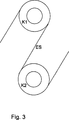
Die
Die
ZITATE ENTHALTEN IN DER BESCHREIBUNG QUOTES INCLUDE IN THE DESCRIPTION
Diese Liste der vom Anmelder aufgeführten Dokumente wurde automatisiert erzeugt und ist ausschließlich zur besseren Information des Lesers aufgenommen. Die Liste ist nicht Bestandteil der deutschen Patent- bzw. Gebrauchsmusteranmeldung. Das DPMA übernimmt keinerlei Haftung für etwaige Fehler oder Auslassungen.This list of the documents listed by the applicant has been generated automatically and is included solely for the better information of the reader. The list is not part of the German patent or utility model application. The DPMA assumes no liability for any errors or omissions.
Zitierte PatentliteraturCited patent literature
- DE 102009008695 A1 [0002] DE 102009008695 A1 [0002]
- DE 1179724 [0003, 0003] DE 1179724 [0003, 0003]
- DE 102007019289 A1 [0003, 0003] DE 102007019289 A1 [0003, 0003]
- DE 19939399 A1 [0003, 0003] DE 19939399 A1 [0003, 0003]
- DE 19614586 B4 [0004, 0004, 0011] DE 19614586 B4 [0004, 0004, 0011]
Zitierte Nicht-PatentliteraturCited non-patent literature
- http://de.wikipedia.org/wiki/Kohlebürste [0004] http://en.wikipedia.org/wiki/Carbon Brush [0004]
- http://de.wikipedia.org/wiki/Steckverbinder [0012] http://en.wikipedia.org/wiki/connector [0012]
- http://de.wikipedia.org/wiki/Kunststoff#Elastomere [0022] http://en.wikipedia.org/wiki/Plastic_Elastomers [0022]
- http://de.wikipedia.org/wiki/Leitfähige_Polymere [0025] http://en.wikipedia.org/wiki/Leitfähige_Polymere [0025]
Claims (15)
Priority Applications (11)
| Application Number | Priority Date | Filing Date | Title |
|---|---|---|---|
| DE102011013827A DE102011013827A1 (en) | 2011-03-14 | 2011-03-14 | Apparatus for continuous heat treatment of electrically conductive extrudate and arrangement of a sliding contact element |
| BR112013022960A BR112013022960A8 (en) | 2011-03-14 | 2012-01-18 | ARRANGEMENT OF A SLIDING CONTACT ELEMENT, METHOD FOR SUPPLYING CURRENT TO A MOBILE CONDUCTOR WITH THE AID OF A SLIDING CONTACT ELEMENT AND DEVICE FOR CONTINUOUS HEAT TREATMENT OF METALLIC STRONG MATERIAL |
| CN201280013270.5A CN103502482B (en) | 2011-03-14 | 2012-01-18 | Apparatus for the continuous thermal treatment of electrically conductive continually cast material and arrangement of a sliding contact element |
| MX2013010402A MX355618B (en) | 2011-03-14 | 2012-01-18 | Apparatus for the continuous thermal treatment of electrically conductive continually cast material and arrangement of a sliding contact element. |
| US14/003,173 US9528165B2 (en) | 2011-03-14 | 2012-01-18 | Apparatus for the continuous thermal treatment of electrically conductive continually cast material and arrangement of a sliding contact element |
| HUE12700617A HUE038973T2 (en) | 2011-03-14 | 2012-01-18 | Apparatus for the continuous thermal treatment of electrically conductive continually cast material and arrangement of a sliding contact element |
| PCT/EP2012/000220 WO2012123048A1 (en) | 2011-03-14 | 2012-01-18 | Apparatus for the continuous thermal treatment of electrically conductive continually cast material and arrangement of a sliding contact element |
| JP2013558311A JP6049021B2 (en) | 2011-03-14 | 2012-01-18 | Current supply structure, method for supplying current to movable conductor, and apparatus for continuous heat treatment of extruded metal material |
| PL12700617T PL2686457T3 (en) | 2011-03-14 | 2012-01-18 | Apparatus for the continuous thermal treatment of electrically conductive continually cast material and arrangement of a sliding contact element |
| EP12700617.9A EP2686457B1 (en) | 2011-03-14 | 2012-01-18 | Apparatus for the continuous thermal treatment of electrically conductive continually cast material and arrangement of a sliding contact element |
| RU2013145708/02A RU2591930C2 (en) | 2011-03-14 | 2012-01-18 | Device for continuous heat treatment of electrically conducting continuous blanks and unit with sliding contact element |
Applications Claiming Priority (1)
| Application Number | Priority Date | Filing Date | Title |
|---|---|---|---|
| DE102011013827A DE102011013827A1 (en) | 2011-03-14 | 2011-03-14 | Apparatus for continuous heat treatment of electrically conductive extrudate and arrangement of a sliding contact element |
Publications (1)
| Publication Number | Publication Date |
|---|---|
| DE102011013827A1 true DE102011013827A1 (en) | 2012-09-20 |
Family
ID=45509453
Family Applications (1)
| Application Number | Title | Priority Date | Filing Date |
|---|---|---|---|
| DE102011013827A Withdrawn DE102011013827A1 (en) | 2011-03-14 | 2011-03-14 | Apparatus for continuous heat treatment of electrically conductive extrudate and arrangement of a sliding contact element |
Country Status (11)
| Country | Link |
|---|---|
| US (1) | US9528165B2 (en) |
| EP (1) | EP2686457B1 (en) |
| JP (1) | JP6049021B2 (en) |
| CN (1) | CN103502482B (en) |
| BR (1) | BR112013022960A8 (en) |
| DE (1) | DE102011013827A1 (en) |
| HU (1) | HUE038973T2 (en) |
| MX (1) | MX355618B (en) |
| PL (1) | PL2686457T3 (en) |
| RU (1) | RU2591930C2 (en) |
| WO (1) | WO2012123048A1 (en) |
Families Citing this family (6)
| Publication number | Priority date | Publication date | Assignee | Title |
|---|---|---|---|---|
| DE102011013827A1 (en) * | 2011-03-14 | 2012-09-20 | Maschinenfabrik Niehoff Gmbh & Co. Kg | Apparatus for continuous heat treatment of electrically conductive extrudate and arrangement of a sliding contact element |
| DE102011077358B3 (en) * | 2011-06-10 | 2012-12-06 | Schleifring Und Apparatebau Gmbh | Vibration-insensitive brush block for slip rings |
| DE102012204830A1 (en) * | 2012-03-26 | 2013-09-26 | Schleifring Und Apparatebau Gmbh | Brush block for a slip ring assembly |
| CN108321986A (en) * | 2016-05-21 | 2018-07-24 | 金福珍 | Using the alternating current generator and its working method of temperature sensor |
| CN109462107A (en) * | 2018-11-19 | 2019-03-12 | 上海发那科机器人有限公司 | A kind of conductive brush device and application method with feedback of constant pressure |
| CN111816367A (en) * | 2019-04-12 | 2020-10-23 | 斯帕有限公司 | Thermal distribution management device for wire processing |
Citations (5)
| Publication number | Priority date | Publication date | Assignee | Title |
|---|---|---|---|---|
| DE1179724B (en) | 1962-12-12 | 1964-10-15 | Niehoff Kommandit Ges Maschf | Device and method for drawing and subsequent annealing and coiling of metallic fine wires, in particular made of copper |
| DE19939399A1 (en) | 1999-08-19 | 2001-02-22 | Niehoff Kg Maschf | Annealing device for annealing metallic billets containing aluminum has contact elements made of electrically conducting material electrically connected to a voltage source |
| DE19614586B4 (en) | 1996-04-12 | 2005-03-17 | Maschinenfabrik Niehoff Gmbh & Co Kg | Apparatus and method for the continuous annealing of metallic bar stock |
| DE102007019289A1 (en) | 2007-04-24 | 2008-10-30 | Maschinenfabrik Niehoff Gmbh & Co. Kg | Wire drawing device i.e. cone-type wire-drawing machine, has drives drivingly connected with shafts, where rotation speed control of drives takes place based on process parameter detected during drawing process |
| DE102009008695A1 (en) | 2009-02-12 | 2010-08-19 | Maschinenfabrik Niehoff Gmbh & Co Kg | Arrangement, product and method for attaching a contact tube on a shaft of a wire continuous resistance annealer |
Family Cites Families (21)
| Publication number | Priority date | Publication date | Assignee | Title |
|---|---|---|---|---|
| SU148078A1 (en) | 1950-03-04 | 1961-11-30 | П.Ф. Булат | Unit for heating steel sheets and strips by electrocontact method |
| JPS5094409A (en) * | 1973-12-24 | 1975-07-28 | ||
| US4110651A (en) * | 1977-03-17 | 1978-08-29 | Litton Systems, Inc. | Brush block assembly |
| JPS589497Y2 (en) * | 1978-12-29 | 1983-02-21 | マブチモ−タ−株式会社 | brush holding device |
| US4431933A (en) | 1978-10-09 | 1984-02-14 | Takaichi Mabuchi | Brush holding device |
| JPS55150681U (en) * | 1979-04-16 | 1980-10-30 | ||
| JPS55150681A (en) | 1979-05-14 | 1980-11-22 | Hitachi Ltd | Electrode circuit of color picture tube |
| SU996478A1 (en) * | 1980-12-15 | 1983-02-15 | Опытное Конструкторско-Технологическое Бюро Института Металлофизики Ан Усср | Resistance heater |
| SU1038371A2 (en) | 1981-03-25 | 1983-08-30 | Предприятие П/Я М-5213 | Apparatus for resistance heating of wire |
| JPS59222535A (en) * | 1983-06-01 | 1984-12-14 | Hitachi Ltd | Current conducting roller |
| DE3405193A1 (en) * | 1984-02-14 | 1985-08-22 | Hübner Elektromaschinen AG, 1000 Berlin | Brush holder for an electrical machine |
| JPH0528920Y2 (en) * | 1986-10-21 | 1993-07-26 | ||
| SU1675365A1 (en) * | 1988-10-31 | 1991-09-07 | Волгоградский Сталепроволочно-Канатный Завод Им.50-Летия Ссср | Apparatus for electric contact heating of wires |
| JPH0529268U (en) * | 1991-09-25 | 1993-04-16 | アスモ株式会社 | Brush spring |
| US5631513A (en) * | 1995-03-20 | 1997-05-20 | Ametek, Inc. | Dynamoelectric brush holder clip and connector |
| DE29702808U1 (en) * | 1997-02-18 | 1997-04-03 | Henrich Gmbh | Continuous annealing for wire material |
| US6227901B1 (en) | 1998-07-10 | 2001-05-08 | Thomas & Betts International, Inc. | Motor boot for a circuit board |
| DK200400405A (en) * | 2004-03-12 | 2005-09-13 | Interroll Joki As | A drum motor with a cable connector |
| WO2008000301A1 (en) * | 2006-06-30 | 2008-01-03 | Amer S.P.A. | Direct current electrical machine |
| US7732971B2 (en) * | 2007-06-01 | 2010-06-08 | Taiwan Long Hawn Enterprise Co. | Carbon brush holder |
| DE102011013827A1 (en) * | 2011-03-14 | 2012-09-20 | Maschinenfabrik Niehoff Gmbh & Co. Kg | Apparatus for continuous heat treatment of electrically conductive extrudate and arrangement of a sliding contact element |
-
2011
- 2011-03-14 DE DE102011013827A patent/DE102011013827A1/en not_active Withdrawn
-
2012
- 2012-01-18 CN CN201280013270.5A patent/CN103502482B/en not_active Expired - Fee Related
- 2012-01-18 RU RU2013145708/02A patent/RU2591930C2/en active
- 2012-01-18 PL PL12700617T patent/PL2686457T3/en unknown
- 2012-01-18 BR BR112013022960A patent/BR112013022960A8/en active Search and Examination
- 2012-01-18 US US14/003,173 patent/US9528165B2/en active Active
- 2012-01-18 HU HUE12700617A patent/HUE038973T2/en unknown
- 2012-01-18 EP EP12700617.9A patent/EP2686457B1/en not_active Not-in-force
- 2012-01-18 JP JP2013558311A patent/JP6049021B2/en not_active Expired - Fee Related
- 2012-01-18 WO PCT/EP2012/000220 patent/WO2012123048A1/en active Application Filing
- 2012-01-18 MX MX2013010402A patent/MX355618B/en active IP Right Grant
Patent Citations (5)
| Publication number | Priority date | Publication date | Assignee | Title |
|---|---|---|---|---|
| DE1179724B (en) | 1962-12-12 | 1964-10-15 | Niehoff Kommandit Ges Maschf | Device and method for drawing and subsequent annealing and coiling of metallic fine wires, in particular made of copper |
| DE19614586B4 (en) | 1996-04-12 | 2005-03-17 | Maschinenfabrik Niehoff Gmbh & Co Kg | Apparatus and method for the continuous annealing of metallic bar stock |
| DE19939399A1 (en) | 1999-08-19 | 2001-02-22 | Niehoff Kg Maschf | Annealing device for annealing metallic billets containing aluminum has contact elements made of electrically conducting material electrically connected to a voltage source |
| DE102007019289A1 (en) | 2007-04-24 | 2008-10-30 | Maschinenfabrik Niehoff Gmbh & Co. Kg | Wire drawing device i.e. cone-type wire-drawing machine, has drives drivingly connected with shafts, where rotation speed control of drives takes place based on process parameter detected during drawing process |
| DE102009008695A1 (en) | 2009-02-12 | 2010-08-19 | Maschinenfabrik Niehoff Gmbh & Co Kg | Arrangement, product and method for attaching a contact tube on a shaft of a wire continuous resistance annealer |
Non-Patent Citations (4)
| Title |
|---|
| http://de.wikipedia.org/wiki/Kohlebürste |
| http://de.wikipedia.org/wiki/Kunststoff#Elastomere |
| http://de.wikipedia.org/wiki/Leitfähige_Polymere |
| http://de.wikipedia.org/wiki/Steckverbinder |
Also Published As
| Publication number | Publication date |
|---|---|
| JP6049021B2 (en) | 2016-12-21 |
| MX355618B (en) | 2018-04-25 |
| RU2013145708A (en) | 2015-04-20 |
| RU2591930C2 (en) | 2016-07-20 |
| MX2013010402A (en) | 2013-10-01 |
| JP2014514440A (en) | 2014-06-19 |
| EP2686457A1 (en) | 2014-01-22 |
| WO2012123048A1 (en) | 2012-09-20 |
| BR112013022960A8 (en) | 2018-04-03 |
| US9528165B2 (en) | 2016-12-27 |
| EP2686457B1 (en) | 2018-05-30 |
| HUE038973T2 (en) | 2018-12-28 |
| CN103502482B (en) | 2015-07-15 |
| BR112013022960A2 (en) | 2016-12-06 |
| CN103502482A (en) | 2014-01-08 |
| US20140084523A1 (en) | 2014-03-27 |
| PL2686457T3 (en) | 2018-10-31 |
Similar Documents
| Publication | Publication Date | Title |
|---|---|---|
| EP2686457B1 (en) | Apparatus for the continuous thermal treatment of electrically conductive continually cast material and arrangement of a sliding contact element | |
| DE202012011808U1 (en) | connecting device | |
| DE102017128173A1 (en) | Pantograph and conductor rail system | |
| WO2018189338A1 (en) | Contact having a composite material | |
| DE102017123653A1 (en) | Temperable sealing element and seal assembly with this | |
| DE102014016443A1 (en) | Brush unit and slip ring assembly with a brush unit | |
| EP1252686A1 (en) | Device for electroconductively contacting an electroconductive part of an outer surface of a pipe, a cable or similar | |
| DE102015110428B4 (en) | sliding contact | |
| EP3393202B1 (en) | Ptc heating element and method for its production | |
| DE102016217673B4 (en) | Electrical contact for a connector, with rotatable rolling contact bodies and electrical plug connection with such a contact | |
| EP2961005B1 (en) | Connector and connecting cable | |
| EP1525900B1 (en) | Process for the formation of electrically contactable conductors on a conductive polymer and products obtainable therewith | |
| EP2337156A1 (en) | Electric plug connector | |
| EP4238394B1 (en) | Potential equalisation of a moving cable of a cable-drawn conveying device | |
| DE202017107220U1 (en) | Pantograph and conductor rail system | |
| DE102015213238A1 (en) | Slinger, bearing and bearing-slinger arrangement | |
| DE202019106683U1 (en) | Pantograph and conductor rail system | |
| DE102019121975A1 (en) | Electric pull coupling and pull coupling with such an electric pull coupling | |
| DE102018119288A1 (en) | Split shaft earthing ring | |
| DE102015204530A1 (en) | exchange contact | |
| DE102019210427A1 (en) | Method for producing an electrically conductive connecting element and connecting arrangement with this connecting element | |
| DE102018004032A1 (en) | Battery connector with contact head | |
| DE102011052387A1 (en) | Spring pressure element used for manufacturing electrical plug connector, has two end portions which are formed as contact regions, and intermediate portion that is formed with an acute angle between contact regions | |
| DE102020209504A1 (en) | hybrid press-fit contact | |
| DE202019105650U1 (en) | High-current contact device |
Legal Events
| Date | Code | Title | Description |
|---|---|---|---|
| R081 | Change of applicant/patentee |
Owner name: SCHUNK KOHLENSTOFFTECHNIK GMBH, DE Free format text: FORMER OWNER: MASCHINENFABRIK NIEHOFF GMBH & CO. KG, 91126 SCHWABACH, DE |
|
| R082 | Change of representative |
Representative=s name: WALLINGER RICKER SCHLOTTER TOSTMANN PATENT- UN, DE |
|
| R005 | Application deemed withdrawn due to failure to request examination |