EP0971083A2 - Kupplungsstück für Dachrinnen - Google Patents
Kupplungsstück für Dachrinnen Download PDFInfo
- Publication number
- EP0971083A2 EP0971083A2 EP99202174A EP99202174A EP0971083A2 EP 0971083 A2 EP0971083 A2 EP 0971083A2 EP 99202174 A EP99202174 A EP 99202174A EP 99202174 A EP99202174 A EP 99202174A EP 0971083 A2 EP0971083 A2 EP 0971083A2
- Authority
- EP
- European Patent Office
- Prior art keywords
- gutter
- wall
- coupling
- coupling member
- shaped
- Prior art date
- Legal status (The legal status is an assumption and is not a legal conclusion. Google has not performed a legal analysis and makes no representation as to the accuracy of the status listed.)
- Granted
Links
Images


Classifications
-
- E—FIXED CONSTRUCTIONS
- E04—BUILDING
- E04D—ROOF COVERINGS; SKY-LIGHTS; GUTTERS; ROOF-WORKING TOOLS
- E04D13/00—Special arrangements or devices in connection with roof coverings; Protection against birds; Roof drainage ; Sky-lights
- E04D13/04—Roof drainage; Drainage fittings in flat roofs, balconies or the like
- E04D13/064—Gutters
- E04D13/0641—Gutter ends
-
- E—FIXED CONSTRUCTIONS
- E04—BUILDING
- E04D—ROOF COVERINGS; SKY-LIGHTS; GUTTERS; ROOF-WORKING TOOLS
- E04D13/00—Special arrangements or devices in connection with roof coverings; Protection against birds; Roof drainage ; Sky-lights
- E04D13/04—Roof drainage; Drainage fittings in flat roofs, balconies or the like
- E04D13/064—Gutters
- E04D13/068—Means for fastening gutter parts together
Definitions
- the invention relates to a coupling piece for roof gutter parts.
- the coupling piece here has a sealing function to prevent water from streaming out of the gutter at the location of the transition.
- Such a coupling piece is known from among others Dutch patent application 70.07068.
- the coupling piece for a gutter box shown in it consists of a lower member and an upper member, which have contours that correspond to the gutter box parts to be coupled.
- the coupling members can be attached to each other by means of screws, the coupling members defining spaces on both sides of the screw connection in which spaces they are able to clamp the gutter box wall located on that side in between them. Between the gutter box wall and the upper member a sealing profile is moreover clamped.
- the upper member and the lower member in the upper portion of the rear wall of the gutter box are provided with cooperating connection means, which locally hold both members of the coupling piece together.
- a surplus of length need not entail an irregularity in the profile, in case of a smooth course of the gutter wall in cross-section, in which case the tension can divide well over the length.
- the (acute) angles In “triangular" gutter or gutter boxes the (acute) angles, however, counteract said redistribution, so that then as well irregularities occur and leakage is possible.
- a main object of the invention is to improve on this.
- the invention provides, from one aspect, a device for roof gutter parts to be connected to each other, which roof gutter parts have a front wall, a bottom wall and a rear wall, which merge into each other via discontinuities -such as buckles, including curved tracks or roundings -, comprising two coupling members, which each substantially follow the shape of the roof gutter parts in cross-section, as well as means for biassing the coupling members to each other to hold the adjacent ends of the roof gutter parts in between them, the upper coupling member being provided with at least one receiving space, such as a channel, for attaching a sealing profile therein suitable for the roof gutter parts which profile is destined to lie on the ends of the roof gutter parts, the sealing profile being formed by injection moulding, the biassing means being adapted to exert a pressure force on the sealing profile to press it against the inner surface of the gutter wall.
- the sealing profile is provided with pre-formed corner or turning areas by injection moulding, as a result of which at placement of the profile on the upper coupling member not only an aligning aid is obtained but it is also prevented that material has to be deformed by bending and local material irregularities arise. In this way the sealing is better ensured.
- the sealing profile and its receiving space in the one coupling member are preferably provided with transverse profiles fining into each other, such as a cam and recess, as a result of which a correct aligning of the sealing profile in circumferential direction is optimized.
- the biassing members comprise first and second connection members, respectively, provided in the rear wall and/or front wall of both coupling members, said connection members cooperating with each other and forming a wedge connection extending in the vertical plane, active transverse to the wall concerned and compressing the sealing profile transversely. In this way the sealing is also promoted on that wall.
- first and/or second connection members extend over nearly the entire height of the wall concerned, as a result of which a regularly distributed optimal sealing is realized over the entire length of said wall.
- first connection means comprise a T-shaped body and the second connection means comprise two inverted L-shaped bodies that face each other, the space defined by the L-shaped bodies increasing in depth towards the bottom.
- This connection can simply -as of its own accord- be realized by sliding both coupling members into each other.
- the first connection means comprise a strip-shaped coupling surface extending in upward direction and preferably facing away from the gutter
- the second connection means comprise a strip-shaped coupling surface cooperating therewith extending in the same upward direction and preferably facing towards the gutter, the upper coupling member having a wall part at that location, which is at an acute angle opening downwards to both strip-shaped coupling surfaces.
- the inner surface of the gutter is at a same acute angle.
- first connection means are formed at the lower coupling member and the second connection means at the upper coupling member.
- Both coupling members are advantageously provided here with stops for keeping both coupling members at a certain minimum distance, so that the pressing in of the sealing profile over its length will be evenly distributed.
- first and second connection means are arranged in the front wall(s) of the coupling members, that is to say the relatively longer walls, so that a larger unimpeded length, as it is not interrupted by provisions for attachment of the gutter, is available for the connection.
- both coupling members on the bottom wall are provided with first and second placement means cooperating with each other, to promote the ease with which the coupling members can be placed on each other.
- first and second placement means can comprise a first U-shaped profiling and a second profiling fitting within there, respectively.
- the gutter parts have an inclined rear wall and both coupling members are provided at the rear wall with third and fourth placement means cooperating with each other, which preferably comprise a third, U-shaped profiling and a fourth profiling fitting within there, respectively.
- first and/or third profilings are integrally formed to the upper coupling member, it then being preferred that the first connection means merge into the first profilings and these merge into the third profilings.
- the sealing profile is provided with an attachment member for attachment in a channel in the upper coupling member and with a flexible sealing lip, which at the side facing the lower coupling member is provided with a flexible tapering end edge.
- the side facing the lower coupling member is provided with a rib at a distance from the end edge and parallel thereto, which rib with the end edge defines an area accommodating a lubricant.
- a chamber for a lubricant is provided which ensures that the sealing profile remains abutting the gutter wall in an undeformed and smooth manner when the gutter parts expand or shrink in longitudinal direction.
- the lubricant moreover being an additional sealing means.
- the invention provides an assembly of two gutter parts and a placement aid for it, both gutter parts at their end edges that face each other being provided with a receiving space for an aligning protrusion on that side of the placement aid, the placement aid being provided with a stop to each side for limiting the extending of the protrusion in the gutter end edge at that location.
- an aid provided in that manner with which the gutter parts can be aligned in transverse direction relative to each other, but also an aid with which the gutter parts in longitudinal direction can be kept from each other at the exact correct distance with respect to each other -adjusted to the dimensions of the coupling piece-.
- the placement aid preferably is elongated and/or symmetrical.
- the application also relates to a placement aid suitable for the assembly described above.
- a gutter assembly 1 comprising a gutter 2a, a gutter 2b and a coupling piece with a lower part 8 and an upper part 9, as well as a placement aid 11.
- the gutters 2a and 2b in this case are so-called "triangular" gutters, which are elaborately described in Dutch patent application 92.02157, the contents of which should be deemed included here.
- the gutters are available with Ubbink Nederland B.V. under the brand name Forta. The have been manufactured by means of extrusion from PVC and can have a length of some metres, for instance 4-6 metres, The Forta gutters are attached to the eave by means of nails, gutter bearers not being necessary.
- the gutters 2a and 2b comprise bottom walls 3a, 3b, upright front walls 6a, 6b, upper edges 7a, 7b, inclined rear walls, 4a, 4b, and bearing walls 5a, 5b, respectively.
- the walls 3-5 are hollow and provided with transverse partitions extending in longitudinal direction, for the necessary firmness. The receiving spaces that are realized in this way can be utilized for other purposes, as will be discussed below regarding the placement aid 11.
- the lower part 8 -made of for instance PVC- of the coupling piece shown in figures 2A and 2B is substantially L-shaped with an end edge which is turned upwards.
- a front part 8a a bottom part 8b, an upwardly inclined rear part 8c and a horizontally extending end part 8d, can be distinguished.
- These parts 8a-d comprise plate-shaped portions 10a-d, respectively, from which in the centre, stems 14a-14d reach upwards to the inside.
- the stems 14a-14d form one continuous stem 14.
- a series of flanges 15a-15d is formed as a unity therewith, which flanges form a continuous flange 15. With the stem 14 the flange 15 forms a T-shaped protrusion from the walls 10.
- the upper part 9 -made for instance of PVC- of the coupling piece shown in figures 3A and 3B is substantially J-shaped, with an upright front part 9a with a buckle at the location of a, b, a bottom part 9b and -via buckle c-parts 9c and 9d inclined obliquely rearwards and upwards and merging into each other via a buckle d.
- These parts comprise a continuous plate-shaped wall 23 located on the inside, consisting of the parts 23a, 23b, 23c and 23d, respectively.
- a U-profile 20 projects perpendicular, in the centre, from the lower or outer side of this shell or plate wall 23, which profile is also continuous and formed by two parallel upright stems 20a, 20b, which with the portion of plate wall 23 situated therebetween define the U-shape.
- the edge of the stems 20a, 20b is turned perpendicular to the inside with edges 22a, 21b.
- a vertical space 21 is defined which tapers upwards and permits access to at least flange 15a, as will be discussed below.
- the portion 23a here is at a small acute angle ⁇ with respect to the edges 22a, b and with regard to the flange 15a.
- the mutual distance between the bodies 20a and 20b corresponds to the width of the flange 15 of the lower part 8.
- a rib 29a, 29b is arranged, and at some distance on the outside thereof an edge area 30a, 30b which to the outside merges into an end edge 32a, 32b which is turned to the outside and with the rib 29a, 29b, forms a receiving space 31a, 31b to the inside for a sealing profile which is to be discussed below.
- the sealing profile 40 shown in the figures 5A-5D for instance is made of EPDM and has a Shore-hardness of 60° plus or minus 5° .
- the sealing profile 40 comprises a main body 41 which is block-shaped in cross-section and at the inside is provided with a placement cam 45.
- the body 41 merges into a lip 42, which at the end merges into two further lips 43 and 44.
- the lip 42 is provided with ribs 46, 47 extending in longitudinal direction and having a sharp tip.
- the lips 43 and 44 are provided with sharp ribs 48 and 49.
- the distance of the rib 49 to the beginning of the lip 44 is equal to the length of the upper surface of the lip 44, so that it can exactly fall in there when the lips 43 and 44 are bent towards each other.
- the lip 42 can also rotate (seen in the plane of the drawing) with respect to the body 41.
- a chamber 50 is formed at the lower side of the lip 44, in which lubricating oil, such as silicone oil can be accommodated.
- the sharp rib 48 not only limits chamber 50, but is also flexible to such an extent that very local irregularities can be followed in a sealing manner. These irregularities may consist of little longitudinal protrusions or longitudinal recesses, which are the result of the extrusion process when making the gutters 2a, 2b, in particular at the location of the aforementioned transverse partitions.
- the sealing strip 40 shown in figure 5A comprises (as seen in the plane of the drawing) an upright portion 40a, a bottom portion 40b, an two inclined upright portions 40c and 40d.
- the lengths of theses portions are such so as to correspond to the lengths in the wall portions 23a-d concerned of the receiving space 31.
- the corners at the location of the buckle locations a, b, c and d correspond to those in the upper part 9, shown in figure 3A.
- This shape is given priorly to the sealing profile 40 by injection moulding. It will be understood that the other sealing profile 40, which has to be placed at the other side of the upper part 90, will be mirror symmetrically formed.
- the body 41 When placing the sealing profile 40 the body 41 is pressed in the receiving channel 31a, which is started with by inserting the placement cam 45 in the recess 33. Subsequently the fingers are moved over the body 41 to press it gradually, moving along the profile, into the receiving space 31. In this way the body 41 is clamp-fined in the receiving space 31. Because of the placement cam 45 one can be sure that the sealing profile 40 is positioned correctly, so that the buckle locations a-d in the sealing profile 40 end up exactly where the buckle locations a-d are in the receiving space 31.
- the sealing profile 40 need not be bent at the location of the corners in the receiving space 31. As a result the actual situation will be equal to the one on which the design is calculated.
- the placement aid 60 consists of a kind of dowel 60, which is symmetrical with respect to the planes S, T and U and is formed by an elongate flat body, which has two arms 61a, 61b which at their ends merge into conical pilot ends 65a, 65b and to the inside via shoulders 63a, 63b merge into thickened parts 62a, 62b.
- a hole 64 is provided for a possible attachment means such as a screw.
- the width of the dowel 60 corresponds to the inner width of longitudinal cavity 71a, 71b which is formed in gutter 2a, 2b by the transverse partitions 70a, 70b in the attachment wall part 5a, 5b of said gutters.
- the following method is used. It is taken as starting point that the gutter 2b is already mounted on the eave.
- the dowel 60 is inserted in the receiving space 71b, until the edge 63b abuts the end edge 62b of the gutter 2b. Possibly the dowel 60 can then be fixated additionally with the help of a screw through the hole 64.
- the gutter 2a with the receiving space 71a is slid over the arm 61a, until the end edge 72a of the gutter 2a abuts the shoulder 63a.
- the gutters 2a and 2b are aligned with respect to each other in the direction Y.
- the gutters 2a and 2b are also fixed with respect to each other in the X-direction.
- the intermediate space between the edges 72a, 72b is such that the coupling piece of the previous figures can easily be placed and the sealing lips can be effective on both sides.
- the lower part 8 is taken and placed from below against the edge areas of the gutters 2a and 2b.
- the turned upper end 18 here abuts the upper wall 7a, 7b of the gutters 2a, 2b from below.
- the upper part 9 is taken, in which the sealing profiles 40 are already arranged, and said part is lowered from above, in which the T-shaped profile formed by stem 14a and the flange 15a is slid in the receiving space 21. Because of the tapering shape the freedom of movement of the T-shaped profile and the turned edges 21a, 21b of the receiving space 21 will become smaller and smaller, until in the assembled situation of upper part 9 and lower part 8 a clamping occurs which is active in horizontal transverse direction, as a result of which the sealing profile is pressed firmly onto the inner surface of the upright gutter wall 6a, 6b. This clamping is furthermore locally promoted by clamping of the edge 7 in the space 28 of the upper part 9.
- the stems 20a, 20b which can extend in the intermediate space between the gutters 2a, 2b, eventually engage over the threaded bushes 16a, 16b and 16c and as a result be correctly aligned.
- the surfaces 17a, 17b and 17c here form a stop for further downward movement of the upper part 9, so that sealing profile 40 cannot become to tightly fitted.
- the gutters 2a, 2b will increase or decrease in length. Because the gutters 2a, 2b with the wall parts 5a, 5b are firmly attached to the eave, this movement will mainly take place in the portions of the gutter which are in transverse direction at a distance thereof, such as in particular the front wall.
- silicone oil is accommodated in the chamber 50, which is limited by the sharp edge 48 and the rib 47.
- the position is indicated of the sealing profile 40 in the mounted situation of the coupling piece.
- the striped-dotted line indicates the level of the upper surface of the gutter wall.
- the silicone oil ensures decrease of friction, but the oil filled chamber 50 moreover forms an additional sealing against water that wants to leak in the direction P.
- leakage way P2 is effectively closed off.
- the chamber 51 and the rib 46 can be active in similar ways as the rib 47 and the chamber 50.
- the gutter parts 102a and 102b are hollow-walled gutters, which with the rear wall are suitable to replace a usual fascia.
- the rear wall 104a, b is provided with a flat receiving space 180a, b, in which angle irons can be accommodated and with which the gutter can directly be attached to the head end edge of the rafters.
- receiving spaces 182a, b are formed by the strip-shaped lips 181a, b, in which spaces the edge of a so-called soffit can be accommodated.
- FIG. 8A and 8B furthermore a lower coupling part 108 and an upper coupling part 109 are shown, in which the lower coupling part 108 is provided with a circumferential T-shaped body 114, 115, which in the bottom portion is provided with bushes 116a, 116b for fastening screws.
- the upper coupling part 109 is provided with holes 124a, 124b for fastening screws and at the outside, continuously provided with a U-shaped profile 120, which defines a wedge-shaped space 121 at the side which is turned to the front, as is the case in the embodiment described before.
- a wedge 155 is formed, with an inclined plane 156 at its side which is facing forward.
- the upper coupling part 109 is provided with channel-shaped receiving spaces 136 for a sealing profile 140, according to the exemplary embodiment discussed earlier.
- a dowel 160 can again be inserted, which is designed a little higher here and instead of a screw hole is provided with a more straight sleeve-like hole 164.
- the dowel 160 is inserted up to the edge 164 in a gutter part 102b.
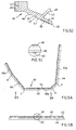
- the sealing profile according to the invention can also be used at the end of a gutter, as is shown in the figures 9A-C.
- the gutter 202 corresponds to the gutter 102 of figures 8A and 8B.
- the end wall here consists of two parts, a lower part 208 and an upper part 209.
- the upper part 209 has an end plate 290, a bent upper edge 292 and a continuous wall 293 extending along the front side, the bottom side and the rear side, which wall at the surface facing the outside is provided with a channel for receiving the sealing strip which is not further shown here, which strip corresponds to the one discussed earlier.
- the angle of the upright portion of the continuous wall situated at the front is equal to the angle of the inner surface of the front wall of the gutter.
- the outside surface is oriented inclined, whereas a end wall 275 forming a vertical plane is integrally formed to the lower coupling part 208, so that also between those two planes a wedge-shape is defined.
- the lower end wall part 208 is substantially U-shaped, with a turned edge 290 having a rear lower end 272 which connects to the lip 281. Because of the U-shape an opening 273 is left free, in which the circumferential wall 293 of the upper end wall part 209 fits.
- the base 274 of the U two snap cams 271 are formed at the front and at the rear, which can snap into the recesses in the inner surface of the end plate 290 provided at the correct location, but which are not further shown here. It is also possible to utilize friction engagement instead of snapping.
- the lower end wall part 208 is placed on the end of the gutter 202, subsequently the upper end wall part 209, then provided with sealing profile, is slid in in the direction D from above and into the lower end wall part 208.
- the circumferential wall 293 and the sealing profile will then end up near and on the inner surface of the gutter 202, in which the cams 271 ensure that the slid-in situation persists.
- the transverse plate 275 here also provides a clamping force in transverse direction.
Landscapes
- Engineering & Computer Science (AREA)
- Architecture (AREA)
- Civil Engineering (AREA)
- Structural Engineering (AREA)
- Roof Covering Using Slabs Or Stiff Sheets (AREA)
- Vehicle Interior And Exterior Ornaments, Soundproofing, And Insulation (AREA)
Applications Claiming Priority (4)
| Application Number | Priority Date | Filing Date | Title |
|---|---|---|---|
| NL1009600 | 1998-07-09 | ||
| NL1009600 | 1998-07-09 | ||
| NL1011231 | 1999-02-05 | ||
| NL1011231A NL1011231C2 (nl) | 1999-02-05 | 1999-02-05 | Koppelstuk voor dakgootdelen. |
Related Child Applications (1)
| Application Number | Title | Priority Date | Filing Date |
|---|---|---|---|
| EP03076424 Division | 2003-05-12 |
Publications (3)
| Publication Number | Publication Date |
|---|---|
| EP0971083A2 true EP0971083A2 (de) | 2000-01-12 |
| EP0971083A3 EP0971083A3 (de) | 2000-04-12 |
| EP0971083B1 EP0971083B1 (de) | 2004-02-04 |
Family
ID=26642839
Family Applications (1)
| Application Number | Title | Priority Date | Filing Date |
|---|---|---|---|
| EP19990202174 Expired - Lifetime EP0971083B1 (de) | 1998-07-09 | 1999-07-05 | Kupplungsstück für Dachrinnen |
Country Status (2)
| Country | Link |
|---|---|
| EP (1) | EP0971083B1 (de) |
| DE (1) | DE69914541T2 (de) |
Cited By (3)
| Publication number | Priority date | Publication date | Assignee | Title |
|---|---|---|---|---|
| USD792576S1 (en) * | 2015-07-30 | 2017-07-18 | Graceland Properties, Llc | Soffit vent |
| AU2021103229B4 (en) * | 2021-06-09 | 2021-11-18 | Source Global Pty. Ltd. | Improved rain gutter bracket |
| EP3985193A1 (de) * | 2020-10-15 | 2022-04-20 | Janssen, Bob | Regenrinne |
Families Citing this family (1)
| Publication number | Priority date | Publication date | Assignee | Title |
|---|---|---|---|---|
| ES2992876T3 (en) * | 2018-10-10 | 2024-12-19 | Munters Italy S P A | Gutter for an evaporative pad of a cooling system |
Citations (1)
| Publication number | Priority date | Publication date | Assignee | Title |
|---|---|---|---|---|
| NL7007068A (de) | 1970-05-15 | 1971-11-17 |
Family Cites Families (6)
| Publication number | Priority date | Publication date | Assignee | Title |
|---|---|---|---|---|
| FR1459071A (fr) * | 1965-09-10 | 1966-04-29 | éléments de raccordement notamment pour sections de gouttières en matière plastique | |
| DE2723250A1 (de) * | 1977-05-24 | 1978-11-30 | Wilhelm Friesch | Vorrichtung zum verbinden von dachrinnenabschnitten |
| US4954015A (en) * | 1990-04-04 | 1990-09-04 | Gsw Inc. | Gutter seal |
| GB9109309D0 (en) * | 1991-04-30 | 1991-06-19 | Alumasc Ltd | Gutter systems |
| GB2266734B (en) * | 1992-05-06 | 1995-08-16 | Mustang Gutter Systems Limited | Guttering connector |
| IT1277787B1 (it) * | 1995-02-07 | 1997-11-12 | Iscom Srl | Dispositivo di giunzione a tenuta tra canali o converse |
-
1999
- 1999-07-05 EP EP19990202174 patent/EP0971083B1/de not_active Expired - Lifetime
- 1999-07-05 DE DE69914541T patent/DE69914541T2/de not_active Expired - Fee Related
Patent Citations (1)
| Publication number | Priority date | Publication date | Assignee | Title |
|---|---|---|---|---|
| NL7007068A (de) | 1970-05-15 | 1971-11-17 |
Cited By (8)
| Publication number | Priority date | Publication date | Assignee | Title |
|---|---|---|---|---|
| USD792576S1 (en) * | 2015-07-30 | 2017-07-18 | Graceland Properties, Llc | Soffit vent |
| EP3985193A1 (de) * | 2020-10-15 | 2022-04-20 | Janssen, Bob | Regenrinne |
| EP3985195A2 (de) | 2020-10-15 | 2022-04-20 | Janssen, Bob | Regenrinne |
| EP3985196A1 (de) | 2020-10-15 | 2022-04-20 | Janssen, Bob | Regenrinne |
| EP3985194A2 (de) | 2020-10-15 | 2022-04-20 | Janssen, Bob | Regenrinne |
| EP3985194A3 (de) * | 2020-10-15 | 2022-06-15 | Janssen, Bob | Regenrinne |
| EP3985195A3 (de) * | 2020-10-15 | 2022-06-15 | Janssen, Bob | Regenrinne |
| AU2021103229B4 (en) * | 2021-06-09 | 2021-11-18 | Source Global Pty. Ltd. | Improved rain gutter bracket |
Also Published As
| Publication number | Publication date |
|---|---|
| DE69914541D1 (de) | 2004-03-11 |
| EP0971083B1 (de) | 2004-02-04 |
| DE69914541T2 (de) | 2004-12-16 |
| EP0971083A3 (de) | 2000-04-12 |
Similar Documents
| Publication | Publication Date | Title |
|---|---|---|
| US8347557B2 (en) | Gutter hanger | |
| US6701674B1 (en) | Snap-on installation gutter protection system, with mounting bracket, and method of use | |
| US20040187434A1 (en) | Cladding apparatus and methods | |
| CN104870729A (zh) | 用于屋顶包覆板的端部搭接系统 | |
| US20140290152A1 (en) | Deck flashing trim system | |
| JPH0833054B2 (ja) | 屋根装置 | |
| EP0971083B1 (de) | Kupplungsstück für Dachrinnen | |
| EP1989366A1 (de) | Modulare dachstruktur für gebäude | |
| MXPA03008125A (es) | Sistema de intermitente. | |
| TWI278562B (en) | A clip | |
| EP1390590B1 (de) | Verkleidungsanordnung und -Verfahren | |
| US4602469A (en) | Roofing/siding system and lock seam therefor | |
| JP3773822B2 (ja) | 縦葺屋根材の接続構造 | |
| US20060260251A1 (en) | Tile wall structure and construction method therefor | |
| ITVR980036U1 (it) | Struttura di copertura piana in lamiera sagomata | |
| EA010876B1 (ru) | Черепица | |
| AU2002249000A1 (en) | Cladding apparatus and methods | |
| EP1001108A1 (de) | Traufenbauweise | |
| HUE035523T2 (en) | Connector plug | |
| JPH0139296Y2 (de) | ||
| EP0851069B1 (de) | Dachelement aus Metallprofilblech | |
| CN222413773U (zh) | 侧向中间防水元件和防水元件的套件 | |
| EP1342862B1 (de) | Modulares System zum Herstellen von Verkleidungsschichten | |
| RU212307U1 (ru) | Профиль для монтажа натяжного потолка | |
| RU16750U1 (ru) | Клипса для крепления плинтуса |
Legal Events
| Date | Code | Title | Description |
|---|---|---|---|
| PUAI | Public reference made under article 153(3) epc to a published international application that has entered the european phase |
Free format text: ORIGINAL CODE: 0009012 |
|
| AK | Designated contracting states |
Kind code of ref document: A2 Designated state(s): BE DE FR GB NL |
|
| AX | Request for extension of the european patent |
Free format text: AL;LT;LV;MK;RO;SI |
|
| PUAL | Search report despatched |
Free format text: ORIGINAL CODE: 0009013 |
|
| AK | Designated contracting states |
Kind code of ref document: A3 Designated state(s): AT BE CH CY DE DK ES FI FR GB GR IE IT LI LU MC NL PT SE |
|
| AX | Request for extension of the european patent |
Free format text: AL;LT;LV;MK;RO;SI |
|
| 17P | Request for examination filed |
Effective date: 20000824 |
|
| AKX | Designation fees paid |
Free format text: BE DE FR GB NL |
|
| 17Q | First examination report despatched |
Effective date: 20010724 |
|
| GRAP | Despatch of communication of intention to grant a patent |
Free format text: ORIGINAL CODE: EPIDOSNIGR1 |
|
| GRAS | Grant fee paid |
Free format text: ORIGINAL CODE: EPIDOSNIGR3 |
|
| GRAA | (expected) grant |
Free format text: ORIGINAL CODE: 0009210 |
|
| AK | Designated contracting states |
Kind code of ref document: B1 Designated state(s): BE DE FR GB NL |
|
| REG | Reference to a national code |
Ref country code: GB Ref legal event code: FG4D |
|
| REF | Corresponds to: |
Ref document number: 69914541 Country of ref document: DE Date of ref document: 20040311 Kind code of ref document: P |
|
| ET | Fr: translation filed | ||
| PLBE | No opposition filed within time limit |
Free format text: ORIGINAL CODE: 0009261 |
|
| STAA | Information on the status of an ep patent application or granted ep patent |
Free format text: STATUS: NO OPPOSITION FILED WITHIN TIME LIMIT |
|
| 26N | No opposition filed |
Effective date: 20041105 |
|
| PGFP | Annual fee paid to national office [announced via postgrant information from national office to epo] |
Ref country code: DE Payment date: 20070830 Year of fee payment: 9 |
|
| PGFP | Annual fee paid to national office [announced via postgrant information from national office to epo] |
Ref country code: GB Payment date: 20070704 Year of fee payment: 9 |
|
| PGFP | Annual fee paid to national office [announced via postgrant information from national office to epo] |
Ref country code: NL Payment date: 20070730 Year of fee payment: 9 Ref country code: BE Payment date: 20070710 Year of fee payment: 9 |
|
| PGFP | Annual fee paid to national office [announced via postgrant information from national office to epo] |
Ref country code: FR Payment date: 20070628 Year of fee payment: 9 |
|
| GBPC | Gb: european patent ceased through non-payment of renewal fee |
Effective date: 20080705 |
|
| NLV4 | Nl: lapsed or anulled due to non-payment of the annual fee |
Effective date: 20090201 |
|
| PG25 | Lapsed in a contracting state [announced via postgrant information from national office to epo] |
Ref country code: DE Free format text: LAPSE BECAUSE OF NON-PAYMENT OF DUE FEES Effective date: 20090203 |
|
| REG | Reference to a national code |
Ref country code: FR Ref legal event code: ST Effective date: 20090331 |
|
| PG25 | Lapsed in a contracting state [announced via postgrant information from national office to epo] |
Ref country code: NL Free format text: LAPSE BECAUSE OF NON-PAYMENT OF DUE FEES Effective date: 20090201 |
|
| PG25 | Lapsed in a contracting state [announced via postgrant information from national office to epo] |
Ref country code: GB Free format text: LAPSE BECAUSE OF NON-PAYMENT OF DUE FEES Effective date: 20080705 |
|
| PG25 | Lapsed in a contracting state [announced via postgrant information from national office to epo] |
Ref country code: FR Free format text: LAPSE BECAUSE OF NON-PAYMENT OF DUE FEES Effective date: 20080731 |
|
| PG25 | Lapsed in a contracting state [announced via postgrant information from national office to epo] |
Ref country code: BE Free format text: LAPSE BECAUSE OF NON-PAYMENT OF DUE FEES Effective date: 20080731 |