EP0970872A2 - Handgeführte Walze mit manueller Lenkung - Google Patents
Handgeführte Walze mit manueller Lenkung Download PDFInfo
- Publication number
- EP0970872A2 EP0970872A2 EP99112555A EP99112555A EP0970872A2 EP 0970872 A2 EP0970872 A2 EP 0970872A2 EP 99112555 A EP99112555 A EP 99112555A EP 99112555 A EP99112555 A EP 99112555A EP 0970872 A2 EP0970872 A2 EP 0970872A2
- Authority
- EP
- European Patent Office
- Prior art keywords
- roller
- supporting frame
- handle bar
- steering
- guide roller
- Prior art date
- Legal status (The legal status is an assumption and is not a legal conclusion. Google has not performed a legal analysis and makes no representation as to the accuracy of the status listed.)
- Withdrawn
Links
- 238000004519 manufacturing process Methods 0.000 description 4
Images

Classifications
-
- B—PERFORMING OPERATIONS; TRANSPORTING
- B62—LAND VEHICLES FOR TRAVELLING OTHERWISE THAN ON RAILS
- B62D—MOTOR VEHICLES; TRAILERS
- B62D51/00—Motor vehicles characterised by the driver not being seated
- B62D51/04—Motor vehicles characterised by the driver not being seated the driver walking
-
- B—PERFORMING OPERATIONS; TRANSPORTING
- B62—LAND VEHICLES FOR TRAVELLING OTHERWISE THAN ON RAILS
- B62D—MOTOR VEHICLES; TRAILERS
- B62D1/00—Steering controls, i.e. means for initiating a change of direction of the vehicle
- B62D1/02—Steering controls, i.e. means for initiating a change of direction of the vehicle vehicle-mounted
- B62D1/12—Hand levers
- B62D1/14—Tillers, i.e. hand levers operating on steering columns
-
- B—PERFORMING OPERATIONS; TRANSPORTING
- B62—LAND VEHICLES FOR TRAVELLING OTHERWISE THAN ON RAILS
- B62D—MOTOR VEHICLES; TRAILERS
- B62D7/00—Steering linkage; Stub axles or their mountings
- B62D7/02—Steering linkage; Stub axles or their mountings for pivoted bogies
Definitions
- the present invention relates to a hand guide roller of manually steering type for leveling ground of roadbed and pavement, and more particularly to a hand guide roller of manually steering type to be steered by pushing and pulling a handle by man power in a horizontal direction.
- rollers for preparing the ground of roadbed and pavement there are hand guide rollers among comparatively small sized rollers. This is demanded for simpleness in structure because of small size, and therefore, the steering is manual by pushing and pulling the handle in the horizontal direction by manpower.
- front and rear rollers are supported by a one main body frame, and a handle bar is fixed to the rear part of the main body frame.
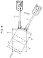
- Advancing directions are, as shown in Fig.5, changed by pushing and pulling the handle bar 9 by manpower in the horizontal directions to steer the front and rear rollers 4, 5 together with the frame. Since this structure is not provided with the steering mechanism, it is very simple and economical in production cost, and thus, such a structure is most suitable to the hand guide roller.
- the invention has been designed in view of problems involved with the prior art, and the man power is not required so much, and accordingly it is an object of this invention to offer such a hand guide roller of manually steering type which can be steered in the turning direction of the handle bar, and is compact in the steering structure.
- this invention is characterized by mutually and turnably connecting a front support frame for supporting a front roller and a rear support frame for supporting a rear roller, directly or indirectly connecting the handle bar to a rear supporting frame, and linking horizontal action of the handle bar with the steering directional action of the rear roller.
- connection between the front and rear supporting frames may depend upon any one of a mechanism via a bearing and turning axis or a mechanism via the turning bearing, as far as mutually turnable mechanism. Both frames may be directly connected or indirectly connected (for example, as shown in the embodiment, the connection via a base plate 30).
- the handle bar may be connected either directly or indirectly to the rear supporting frame, but the structure must be that the actuation of the handle bar must be transmitted, as it is, to the steering actuation of the rear supporting frame.
- the "indirect connection” is, as mentioned in a later embodiment, meant by such a connection via a rod as a linking mechanism.
- the present invention is that if the handle bar is pushed or pulled horizontally, the actuation of the handle bar is transmitted as it is to the steering actuation of the rear supporting frame, so that the horizontally directional actuation of the handle bar is linked with the steering directional actuation of the rear roller. Namely, if the handle bar is pushed to the right, the rear roller is tilted right upward, and if advancing under such a state, the car is steered to the right direction. Reversely, if the handle bar is pushed to the left, the car is steered to the left direction. Thus, the direction of moving the handle bar agrees with the steering direction of the car main body, so that an operator is not demanded for experience and can easily steer.
- the steering structure is basically simple in that the front supporting frame and the rear supporting frame are mutually turnable, resulting in low production cost.
- the rear supporting frame for supporting the rear roller is linked with the pushing and pulling of the handle bar.
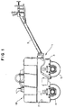
- reference numeral 1 designates a roller car frame
- 2 is a front supporting frame
- 3 is a rear supporting frame
- 4 is a front roller
- 5 is a rear roller
- 6 is a turning bearing
- 7 is a vibration generator
- 8 is a rod
- 9 is a handle bar
- 10 is a handle axis
- 18 is a driving part.
- the car frame 1 comprises the front supporting frame 2 and the rear supporting frame 3, and on the car frame 1, the driving part 18 composed of the engine and others are provided via a base plate 16.
- the rear supporting frame 3 is composed of a part of the upper side of the rear roller 5, while the front supporting frame 2 is formed to cover largely over the rear supporting frame 3.
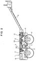
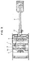
- the front supporting frame 2 and the rear supporting frame 3 are mutually turnable via the turning bearing 6 at the center of the car. More specifically, an outer wheel 60 of the turning bearing 6 is screwed with bolts, respectively in the front supporting frame 2, and an inner wheel 61 is screwed in a base plate 30 extending from the rear supporting frame 3.
- the front supporting frame 2 is turnably pivoted at the rear part with the handle bar 9.
- a bracket of the handle axis 10 is connected with the rod 8, and the end part of the rod 8 is connected with the base plate 30.
- the base plate 30 is a member which extends from the rear supporting plate 3 and is screwed with the inner wheel 61 of the turning bearing 6.
- the vibration generator 7 is installed under the turning bearing 6, and the vibration therefrom is respectively transmitted to the front roller 4 via the front supporting frame 2, and to the rear roller 5 via the turning bearing 6, the base plate 30 and the rear supporting frame 3.
- the pushing direction of the handle bar 9 agrees with the steering direction of the car 1, so that the operator can easily operate without much experience.
- the labor is sufficient with a small amount.
- the car frame 1 is almost composed with the front supporting frame 2, and since the rear supporting frame 3 for supporting the rear roller 5 is composed with the rear one part of the car main body, a load to be required for moving the handle bar 9 is considerably reduced, and people with less physical strength can operate the steering.
- the steering mechanism is sufficient with mutual turnability of the front supporting frame 2 and the rear supporting frame 3, so that the structure is simple with cheap manufacturing cost.
- the pushing direction of the handle bar 9 agrees with the steering direction of the car 1, so that the operator can easily operate without much experience. Further, only the moving of the rear roller is required, and the pushing and pulling labor of the handle bar.
- the steering mechanism is very simple, and the manufacturing may be realized with low cost.
Landscapes
- Engineering & Computer Science (AREA)
- Chemical & Material Sciences (AREA)
- Combustion & Propulsion (AREA)
- Transportation (AREA)
- Mechanical Engineering (AREA)
- Road Paving Machines (AREA)
- Guiding Agricultural Machines (AREA)
- Forklifts And Lifting Vehicles (AREA)
Priority Applications (1)
| Application Number | Priority Date | Filing Date | Title |
|---|---|---|---|
| EP99112555A EP0970872A3 (de) | 1998-07-07 | 1999-07-01 | Handgeführte Walze mit manueller Lenkung |
Applications Claiming Priority (4)
| Application Number | Priority Date | Filing Date | Title |
|---|---|---|---|
| JP498098U | 1998-07-07 | ||
| JP1998004980U JP3055608U (ja) | 1998-07-07 | 1998-07-07 | 手動操舵式ハンドガイドローラ |
| JP498098 | 1998-07-07 | ||
| EP99112555A EP0970872A3 (de) | 1998-07-07 | 1999-07-01 | Handgeführte Walze mit manueller Lenkung |
Publications (2)
| Publication Number | Publication Date |
|---|---|
| EP0970872A2 true EP0970872A2 (de) | 2000-01-12 |
| EP0970872A3 EP0970872A3 (de) | 2000-12-13 |
Family
ID=26153036
Family Applications (1)
| Application Number | Title | Priority Date | Filing Date |
|---|---|---|---|
| EP99112555A Withdrawn EP0970872A3 (de) | 1998-07-07 | 1999-07-01 | Handgeführte Walze mit manueller Lenkung |
Country Status (1)
| Country | Link |
|---|---|
| EP (1) | EP0970872A3 (de) |
Family Cites Families (3)
| Publication number | Priority date | Publication date | Assignee | Title |
|---|---|---|---|---|
| NL6506743A (de) * | 1964-06-27 | 1965-12-28 | ||
| CH480499A (de) * | 1968-10-18 | 1969-10-31 | Ammann U Maschf Ag | Tandemwalze mit Lenkdeichsel |
| FR2052137A5 (de) * | 1969-07-23 | 1971-04-09 | Richier Sa |
-
1999
- 1999-07-01 EP EP99112555A patent/EP0970872A3/de not_active Withdrawn
Non-Patent Citations (1)
| Title |
|---|
| None |
Also Published As
| Publication number | Publication date |
|---|---|
| EP0970872A3 (de) | 2000-12-13 |
Similar Documents
| Publication | Publication Date | Title |
|---|---|---|
| US7644806B2 (en) | Low lift truck | |
| US6343907B1 (en) | Low-lift fork truck | |
| EP0971073B1 (de) | Handgeführte und handsteuerbare Strassenwalze | |
| TW558548B (en) | Working vehicle with transverse moving system | |
| EP0970872A2 (de) | Handgeführte Walze mit manueller Lenkung | |
| EP1323615B1 (de) | Lenkvorrichtung für ein Flurförderzeug | |
| JP4267731B2 (ja) | 自動二輪車用風防装置 | |
| JP3055608U (ja) | 手動操舵式ハンドガイドローラ | |
| EP1223142A3 (de) | Hubwagen | |
| JP4414033B2 (ja) | 農薬散布車 | |
| JPH089332B2 (ja) | ハンドリフトトラック | |
| JP2008285021A (ja) | 電動車フレーム | |
| EP1186567A1 (de) | Fahrgestell für Arbeitsbühne | |
| JP2586859Y2 (ja) | コンクリートレベラー | |
| JPH0117333Y2 (de) | ||
| JPS5830771Y2 (ja) | トラクタ−の安全フレ−ム取付構造 | |
| JPH068860A (ja) | 農用トラクタの支持フレーム連結構造 | |
| JP3521153B2 (ja) | 車両用エンジン緊急停止装置 | |
| JP2002145073A (ja) | ローリフトトラック | |
| JP3140013B2 (ja) | 横行システムを持ったフォークリフト | |
| JPH0625497Y2 (ja) | ブーム付き作業車のペダル装置 | |
| JP3121802B2 (ja) | フォークリフトのマスト装置 | |
| JP3272339B2 (ja) | 横行システムを持ったフォークリフト | |
| JP2771120B2 (ja) | 除雪作業車 | |
| JPH0216912A (ja) | 草刈作業車 |
Legal Events
| Date | Code | Title | Description |
|---|---|---|---|
| PUAI | Public reference made under article 153(3) epc to a published international application that has entered the european phase |
Free format text: ORIGINAL CODE: 0009012 |
|
| AK | Designated contracting states |
Kind code of ref document: A2 Designated state(s): DE FR GB |
|
| AX | Request for extension of the european patent |
Free format text: AL;LT;LV;MK;RO;SI |
|
| PUAL | Search report despatched |
Free format text: ORIGINAL CODE: 0009013 |
|
| AK | Designated contracting states |
Kind code of ref document: A3 Designated state(s): AT BE CH CY DE DK ES FI FR GB GR IE IT LI LU MC NL PT SE |
|
| AX | Request for extension of the european patent |
Free format text: AL;LT;LV;MK;RO;SI |
|
| AKX | Designation fees paid |
Free format text: DE FR GB |
|
| STAA | Information on the status of an ep patent application or granted ep patent |
Free format text: STATUS: THE APPLICATION IS DEEMED TO BE WITHDRAWN |
|
| 18D | Application deemed to be withdrawn |
Effective date: 20010614 |