EP0969973B1 - Schreibgerät - Google Patents
Schreibgerät Download PDFInfo
- Publication number
- EP0969973B1 EP0969973B1 EP98913056A EP98913056A EP0969973B1 EP 0969973 B1 EP0969973 B1 EP 0969973B1 EP 98913056 A EP98913056 A EP 98913056A EP 98913056 A EP98913056 A EP 98913056A EP 0969973 B1 EP0969973 B1 EP 0969973B1
- Authority
- EP
- European Patent Office
- Prior art keywords
- sealing element
- barrel
- marking
- instrument according
- tip
- Prior art date
- Legal status (The legal status is an assumption and is not a legal conclusion. Google has not performed a legal analysis and makes no representation as to the accuracy of the status listed.)
- Expired - Lifetime
Links
- 238000007789 sealing Methods 0.000 claims description 128
- 238000005096 rolling process Methods 0.000 claims description 7
- 239000012528 membrane Substances 0.000 claims description 4
- 230000006835 compression Effects 0.000 claims description 3
- 238000007906 compression Methods 0.000 claims description 3
- 230000007246 mechanism Effects 0.000 description 7
- 239000000463 material Substances 0.000 description 6
- 238000010276 construction Methods 0.000 description 4
- 238000006073 displacement reaction Methods 0.000 description 4
- 230000000694 effects Effects 0.000 description 2
- 239000012530 fluid Substances 0.000 description 2
- 238000004519 manufacturing process Methods 0.000 description 2
- 230000004048 modification Effects 0.000 description 2
- 238000012986 modification Methods 0.000 description 2
- 230000002411 adverse Effects 0.000 description 1
- 230000009286 beneficial effect Effects 0.000 description 1
- 229920001577 copolymer Polymers 0.000 description 1
- 239000000835 fiber Substances 0.000 description 1
- 239000007788 liquid Substances 0.000 description 1
- 230000007774 longterm Effects 0.000 description 1
- 238000000034 method Methods 0.000 description 1
Images





Classifications
-
- B—PERFORMING OPERATIONS; TRANSPORTING
- B43—WRITING OR DRAWING IMPLEMENTS; BUREAU ACCESSORIES
- B43K—IMPLEMENTS FOR WRITING OR DRAWING
- B43K8/00—Pens with writing-points other than nibs or balls
- B43K8/24—Pens with writing-points other than nibs or balls characterised by the means for retracting writing-points
-
- B—PERFORMING OPERATIONS; TRANSPORTING
- B43—WRITING OR DRAWING IMPLEMENTS; BUREAU ACCESSORIES
- B43K—IMPLEMENTS FOR WRITING OR DRAWING
- B43K7/00—Ball-point pens
- B43K7/12—Ball-point pens with retractable ball points
-
- B—PERFORMING OPERATIONS; TRANSPORTING
- B43—WRITING OR DRAWING IMPLEMENTS; BUREAU ACCESSORIES
- B43K—IMPLEMENTS FOR WRITING OR DRAWING
- B43K8/00—Pens with writing-points other than nibs or balls
- B43K8/02—Pens with writing-points other than nibs or balls with writing-points comprising fibres, felt, or similar porous or capillary material
- B43K8/028—Movable closure or gate
Definitions
- This invention relates to marking instruments and in particular the invention is concerned with retractable marking instruments, that is marking instruments of the type comprising a barrel, and a member carrying a marking tip which is movable relative to the barrel, frequently by means of a retraction mechanism included within a rear end portion of the barrel, for displacement between an operative position in which the marking tip protrudes from the open forward end of the barrel, and an inoperative position in which the marking tip is retracted within the barrel.
- Retractable marking instruments are convenient when the marking tip is of a kind which will not dry out during periods of non-use, such as a ball point pen which use a viscous ink, since it is not then required to form an enclosure around the tip when it is retracted.
- a marking instrument including a barrel having an opening at the forward end thereof, a member carrying a marking tip for movement through said opening between an operative position protruding from said barrel and an inoperative position retracted within said barrel, an annular sealing element arranged within said barrel for frictional contact with an inner surface of said barrel and said member characterized in that said sealing element rolls therebetween during movement of said marking tip between said operative and inoperative positions.
- a sealing element as provided in a marking instrument according to the invention is economic to manufacture and assemble within the barrel and it can provide an effective sealing performance without demanding a barrel of large diameter.
- the sealing effect can be produced by the sealing element in different ways.
- the sealing element may close the barrel interior forwardly of the retracted tip to form an enclosed space around the tip.
- the sealing element may contact or envelope the retracted marking tip to seal off the tip.
- the sealing element is conveniently formed substantially in the shape of a torus and it may have slits or slots around its periphery to reduce the stresses created in the material of the sealing element during its rolling motion.
- the sealing element may be made of a soft rubber or rubber-like material with a substantially circular initial cross-section which is deformed into oval shape when the sealing element is engaged between the barrel and the marking member. It may be advantageous for the sealing element to roll through substantially one complete revolution during movement of the marking tip between the inoperative and operative positions so that, in the normal rest positions of the sealing element, the natural inner and outer surfaces of the sealing element are at the inner and outer peripheries, respectively. To relieve compressive stresses on the sealing element when the marking tip is in the extended operative position, the internal barrel surface over which the sealing element rolls can be arranged to taper rearwardly.
- a lost motion connection can be included enabling the member carrying the marking tip to move relative to the barrel, without being accompanied by rolling of the sealing element, over a forward portion of the stroke when the sealing element does not make contact with the marking tip.
- the lost motion connection is between the sealing element and the member carrying the marking tip and comprises a collar slidable longitudinally on the member. During advancement of the marking tip from the retracted position, the sealing element initially rolls between the barrel and the marking tip and then rolls off of the marking tip and onto the collar.
- the member carrying the marking tip continues to move forwardly to bring the marking tip into the operative position while the sealing element and collar remain stationary relative to the barrel.
- the collar is biased to a forward most position by a spring, such as a coil compression spring.
- the invention is especially applicable to a writing instrument in which a replaceable refill unit is accommodated in the pen barrel and includes an ink reservoir as well as a writing tip. With such pens the sealing element could conveniently be arranged for replacement with the refill unit.
- the retractable pen partially illustrated in Figures 1-3 has a barrel 1 housing a replaceable refill unit 2 which, in a manner well known in the art, includes an ink reservoir and a writing tip 3.
- the pen includes a retraction mechanism for advancing and retracting the refill unit relative to the barrel for moving the writing tip from the retracted inoperative position shown in Figure 1 to the extended operative position of Figure 3 in which the marking tip protrudes through the opening 4 at the forward end of the barrel.
- the retraction mechanism has not been shown as it forms no part of the present invention and it may be any of the many forms of retraction mechanisms known in the art which provide for axial displacement of the refill unit, preferably without requiring the unit to rotate.
- annular sealing element 6 Received within the barrel 1 for cooperation with the refill unit 2 is an annular sealing element 6 having the form of a torus with a small central through hole 7 as shown in Figure 4.
- the sealing element is made of a soft rubber or rubber-like material, such as a copolymer, so that it makes frictional, non-sliding contact with the interior surface of the barrel 1 and with the refill unit 2.
- the sealing element has a substantially circular initial cross-section, but can be readily deformed into an oval shape between the barrel and refill unit. In the retracted position of the marking tip the sealing element 6 closes the internal cross-section of the barrel forwardly of the writing tip, the sealing element being radially compressed within the barrel so that the hole 7 through the sealing element is held closed.
- the sealing element 6 rolls between the barrel and the refill unit, as indicated by the arrows in Figure 2, and is displaced towards the forward end of the barrel, the sealing element occupying the position shown in Figure 3 when the writing tip is in the fully extended operative position.
- the sealing element 6 rolls back to the Figure 1 position so as to close off the barrel.
- a further sealing device of any convenient form can be provided between the barrel and the refill unit rearwardly of the sealing element 6.
- the further sealing device could be provided by a second rolling sealing element.
- the sealing element 6 can be provided with slots 10 around its periphery as shown in Figure 5. When the sealing element is compressed within the barrel the slots can become closed up so that a sealing cooperation between the sealing elements and the barrel is still obtained.
- FIGS. 6 and 7 show such a sealing arrangement in connection with a roller ball point.
- the hole 7 through the sealing element 6 remains open, but the sealing element engages the tip so that the annular orifice defined between the ball 12 and the rim 14 of the tip is covered by the sealing element which makes contact with the ball and rim.
- FIG. 8 shows an embodiment in which a rear stop is provided by an internal shoulder 15 in the barrel 1, the sealing element being located adjacent the shoulder when the refill unit 2 is retracted.
- Figure 8 also depicts the sealing element closing off the barrel to seal a space 16 around the writing tip.
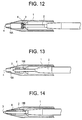
- Figures 12-14 illustrate an embodiment in which opposed shoulders 15A and 15B are spaced apart along the barrel to define front and rear end stops, respectively. The sealing element 6 is confined between the two shoulders and rolls along the barrel between the shoulders during projection and retraction movements of the refill unit.
- the sealing element abuts the shoulder 15A when the writing tip is fully projected and abuts the shoulder 15B when the refill unit is fully retracted. In the fully retracted position the sealing element seals the writing tip as described above. Confining the sealing element between opposed stops will preclude any tendency for the sealing element to migrate along the barrel or refill unit, which could have an adverse effect on its sealing performance.
- the barrel has a substantially constant diameter over the internal surface portion along which the sealing element is arranged to roll.
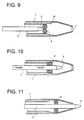
- Figures 9-11 illustrate another construction in which the barrel surface portion 18 with which the sealing element has rolling contact tapers rearwardly.
- the sealing element is allowed to expand when the writing tip is advanced to its operative position ( Figure 11) relieving the stresses within the material of the sealing element when it is not required to perform a sealing function, and the sealing element 6 becomes radially compressed when the writing tip is retracted ( Figure 9) to ensure an effective seal at or adjacent the tip 3.
- the sealing element may be desirable for the sealing element to roll through a complete turn to avoid it becoming parked in a stressed condition when the refill unit occupies the fully retracted or fully projected position.
- This in addition to the fact that the sealing element itself moves longitudinally of the barrel when the refill unit is displaced between the retracted and operative positions, means that the stroke of the refill unit between these positions may be relatively long.
- This potential drawback can be avoided by providing the refill unit with a lost motion device, e.g. a collar which is movable longitudinally relative to the writing tip.
- a lost motion device e.g. a collar which is movable longitudinally relative to the writing tip.
- An embodiment incorporating a sliding collar arrangement is illustrated in Figures 15 to 17.
- the collar has the form of a sleeve 20 which is slidable on the reduced diameter forward end portion of the refill unit 2 between a stop defined adjacent the writing tip and a shoulder formed by an increase in diameter of the refill unit 2.
- the sealing element 6 seals off the writing tip 3 in the same manner as described above with reference to the embodiment of Figures 1-3.
- the sealing element 6 rolls forwardly with respect to the barrel 1 and rearwardly relative to the refill unit 2 until it is engaged substantially completely with the sleeve, as shown in Figure 16.
- the forward end of the barrel tapers towards the opening 4 at its front end and this produces compression of the sealing element as it rolls forwardly in the barrel to ensure good frictional cooperation with the sleeve in order to obtain the desired movements of the sleeve and sealing element relative to the refill unit 2.
- it is preferably arranged to have frictional contact with the refill unit, for which purpose the sleeve may be slit longitudinal so that the sleeve grips the refill unit, or the sleeve can be dimpled.
- Other ways of achieving the desired frictional cooperation are of course possible.
- the frictional cooperation between the sleeve and refill unit should allow the sleeve to slide to a forwardmost position before the sealing element is caused to roll.
- the collar of the lost motion device is biased to a forward most position on the refill unit by a spring 22.
- the spring is a coil spring which is interposed between the collar 20 and a shoulder defined between the reduced diameter front end part of the refill unit and a larger diameter rear part of the refill unit.
- the collar 20 is formed integrally with the spring by a closely coiled spring section.
- the sealing arrangement in this embodiment functions as described in connection with Figures 15 to 17, but the spring 22 provides additional reliability in ensuring correct sliding movement of the collar over a large number of operations of the pen retraction mechanism.
- a shoulder on the refill unit limiting forward displacement of the collar 20 is not essential and as an alternative the rear end of the spring 22 can be anchored to the refill unit so the spring also serves to limit forward movement of the collar 20 relative to the refill unit.
- the embodiment of the retractable pen shown in Figures 21 to 23 is the same as that of Figures 17 to 20 except that the sealing element is accommodated between front and rear stop shoulders 15A and 15B within the barrel 1, as described above in relation to Figures 12-14.
- the stop shoulders limit the movement of the sealing element 6 and define its two end positions within the barrel 1, thereby achieving additional security of correct operation of the sealing arrangement over long term use of the writing instrument during which the writing tip may be advanced and retracted a very large number of times.
- the stop shoulders 15A,15B are closer together in the pen of Figs. 21-23, compared with that of Figs. 12-14, since the movement of the sealing element within the barrel is reduced as a consequence of the lost motion device constituted by the collar 20.
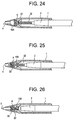
- Figures 24 to 26 an embodiment of a retractable pen which is identical to that of Figures 21 to 23 other than for the fact that the barrel section between the stop shoulders 15A,15B includes a forward portion which tapers inwardly.
- the tapered portion allows the conical nose of the barrel to be made shorter, which may be desirable with a view to improving tip visibility during writing.
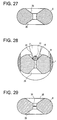
- FIG. 27 and 28 A modified form of sealing element suitable for use in any of the embodiments described above is illustrated in Figures 27 and 28.
- the sealing element can seal a ball point tip by closing the annular orifice between the ball and the rim of the tip, the sealing element being arranged to contact both ball and rim for this purpose.
- the sealing element 6 of Figure 27 is formed with a conical inner sealing surface portion 25 which is more strongly inclined to the axis of the tip than that surface portion of a sealing element of circular cross-section which engages the writing tip. In this way reliable sealing contact between the ball and rim of the tip is ensured.
- Figure 28 which shows the sealing element of Figure 27 installed in a pen and in sealing cooperation with the ball 12 and rim 14 of the writing tip.
- the second conical surface 26 is provided so that the sealing element is symmetrical and does not therefore require orientation during assembly with the refill unit.
- a conical sealing surface for engagement with the writing tip is not essential of course and Figure 30 illustrates an embodiment in which the sealing element 6 has a concave surface 28. This surface can lie at a large angle to the writing tip axis in the region where the surface makes contact with the ball 12 and rim 14 of the writing tip 2 so as to ensure effective sealing of the retracted tip.
- the sealing element of Figure 29 is adapted to provide additional security against dry out of ink before use of a refill unit by tightly sealing around the tip and for the purpose the sealing element incorporates a membrane 30, conveniently moulded integrally with the sealing element, to close the passage through the centre of the sealing element.
Landscapes
- Mechanical Pencils And Projecting And Retracting Systems Therefor, And Multi-System Writing Instruments (AREA)
- Pens And Brushes (AREA)
- Closing Of Containers (AREA)
Claims (17)
- Schreibgerät, das einen Schaft (1) mit einer Öffnung (4) an seinem vorderen Ende, ein Element (2), das eine Schreibspitze (3) zur Bewegung durch die Öffnung (4) zwischen einer Arbeitsposition, in der sie aus dem Schaft (1) vorragt, und einer Ruheposition trägt, in der sie in den Schaft (1) eingezogen ist, und ein ringförmiges Abdichtungselement (6) enthält, das für Reibungskontakt mit einer Innenfläche des Schaftes (1) und dem Element (2) in dem Schaft (1) angeordnet ist, dadurch gekennzeichnet, daß das Abdichtungselement (6) während der Bewegung der Schreibspitze (3) zwischen den Arbeits- und Ruhepositionen dazwischen rollt.
- Schreibgerät nach Anspruch 1, dadurch gekennzeichnet, daß das Abdichtungselement (6) im wesentlichen in Gestalt eines Torus ausgebildet ist.
- Schreibgerät nach Anspruch 1 oder 2, dadurch gekennzeichnet, daß das Abdichtungselement (6) Schlitze (10) aufweist, die um dessen Umfang im Abstand angeordnet sind.
- Schreibgerät nach Anspruch 1 bis 3, dadurch gekennzeichnet, daß ein Loch (7) durch das Abdichtungselement (6) durch radiales Zusammendrücken des Abdichtungselements (6) in dem Schaft (1) verschlossen wird, wenn die Schreibspitze (3) sich in der Ruheposition befindet.
- Schreibgerät nach irgendeinem der Ansprüche 1 bis 4, dadurch gekennzeichnet, daß das Abdichtungselement (6) die Schreibspitze (3) in deren eingezogenen Ruheposition berührt.
- Schreibgerät nach irgendeinem der Ansprüche 1 bis 5, dadurch gekennzeichnet, daß das ringförmige Abdichtungselement (6) eine im wesentlichen konische oder konkave Innenfläche zur Zusammenwirkung mit der Schreibspitze (3) aufweist.
- Schreibgerät nach irgendeinem der Ansprüche 1 bis 6, dadurch gekennzeichnet, daß das Innere des Schaftes Anschlagmittel (15, 15B) zum Begrenzen der Rollbewegung des Abdichtungselements (6) in rückwärtiger Richtung entlang des Schaftes (1) enthält.
- Schreibgerät nach irgendeinem der Ansprüche 1 bis 7, dadurch gekennzeichnet, daß das Innere des Schaftes (1) Anschlagmittel (15A) zum Begrenzen der Bewegung des Abdichtungselements (6) nach vorne entlang dem Schaft (1) enthält.
- Schreibgerät nach irgendeinem der Ansprüche 1 bis 8, dadurch gekennzeichnet, daß der Schaft (1) einen sich nach hinten verjüngenden Innenflächenbereich (18) enthält, entlang dessen das Abdichtungselement (6) rollt, wenn die Schreibspitze (3) zwischen den Arbeits- und Ruhepositionen bewegt wird.
- Schreibgerät nach irgendeinem der Ansprüche 1 bis 9, dadurch gekennzeichnet, daß der Schaft (1) einen sich nach vorne verjüngenden Innenflächenbereich enthält, entlang dessen das Abdichtungselement (6) rollt, wenn die Schreibspitze (3) aus der Ruheposition zur Arbeitsposition vorbewegt wird.
- Schreibgerät nach irgendeinem der Ansprüche 1 bis 10, dadurch gekennzeichnet, daß das Abdichtungselement (6) über im wesentlichen eine oder mehrere vollständige Umdrehung(en) während der Bewegung der Schreibspitze (3) zwischen den Ruhe- und Arbeitspositionen rollt.
- Schreibgerät nach irgendeinem der Ansprüche 1 bis 10, dadurch gekennzeichnet, daß eine Leergangverbindung vorgesehen ist und der Schreibspitze (3) erlaubt, sich in Längsrichtung des Schaftes (1) zu bewegen, ohne eine Rollbewegung des Abdichtungselements (6) während eines vorderen Endteils des Bewegungshubs der Schreibspitze (3) zwischen den Arbeits- und Ruhepositionen zu verursachen.
- Schreibgerät nach Anspruch 12, dadurch gekennzeichnet, daß die Leergangverbindung eine Leergangeinrichtung umfaßt, die zwischen dem Abdichtungselement (6) und dem die Schreibspitze (3) tragenden Element (2) positioniert ist.
- Schreibgerät nach Anspruch 13, dadurch gekennzeichnet, daß die Leergangeinrichtung einen gleitfähig auf dem Element (2) getragenen Bund (2) umfaßt.
- Schreibgerät nach Anspruch 14, dadurch gekennzeichnet, daß der Bund (2) von einer Feder (22) auf dem Element (2) nach vorne getrieben wird.
- Schreibgerät nach Anspruch 15, dadurch gekennzeichnet, daß die Feder (22) eine Spiralfeder ist, wobei ein vorderer Teil der Feder (22) deren dicht gekoppelten Spiralen aufweist und den Bund (20) bildet.
- Schreibgerät nach irgendeinem der vorangehenden Ansprüche, dadurch gekennzeichnet, daß das Abdichtungselement (6) mit einer das dort hindurchgehende Loch (7) verschließenden Membran (30) versehen ist, wobei die Membran (30) durch Vorbewegen der Schreibspitze (3) während der Bewegung aus der Ruheposition zur Arbeitsposition zerreißbar ist.
Applications Claiming Priority (3)
| Application Number | Priority Date | Filing Date | Title |
|---|---|---|---|
| GBGB9706461.2A GB9706461D0 (en) | 1997-03-27 | 1997-03-27 | Marking instruments |
| GB9706461 | 1997-03-27 | ||
| PCT/US1998/005688 WO1998043828A1 (en) | 1997-03-27 | 1998-03-24 | Marking instruments |
Publications (2)
| Publication Number | Publication Date |
|---|---|
| EP0969973A1 EP0969973A1 (de) | 2000-01-12 |
| EP0969973B1 true EP0969973B1 (de) | 2002-06-05 |
Family
ID=10810022
Family Applications (1)
| Application Number | Title | Priority Date | Filing Date |
|---|---|---|---|
| EP98913056A Expired - Lifetime EP0969973B1 (de) | 1997-03-27 | 1998-03-24 | Schreibgerät |
Country Status (8)
| Country | Link |
|---|---|
| EP (1) | EP0969973B1 (de) |
| JP (1) | JP4082466B2 (de) |
| CN (1) | CN1251553A (de) |
| AU (1) | AU6769398A (de) |
| BR (1) | BR9808423A (de) |
| DE (1) | DE69805778T2 (de) |
| GB (1) | GB9706461D0 (de) |
| WO (1) | WO1998043828A1 (de) |
Families Citing this family (2)
| Publication number | Priority date | Publication date | Assignee | Title |
|---|---|---|---|---|
| DE102005014468A1 (de) * | 2005-03-30 | 2006-10-05 | Schwan-Stabilo Cosmetics Gmbh & Co. Kg | Auftraggerät |
| AU2019202021B1 (en) * | 2019-03-13 | 2019-05-23 | Qingdao Keka Stationery Co., Ltd. | A Multifunctional Pen |
Family Cites Families (3)
| Publication number | Priority date | Publication date | Assignee | Title |
|---|---|---|---|---|
| US2946311A (en) * | 1954-12-01 | 1960-07-26 | Burnie J Craig | Writing instrument |
| US3594091A (en) * | 1969-01-29 | 1971-07-20 | Keith T Bleuer | Pen |
| FR2538762A1 (fr) * | 1982-12-30 | 1984-07-06 | Dupont S T | Perfectionnements aux stylographes a cartouches-recharges |
-
1997
- 1997-03-27 GB GBGB9706461.2A patent/GB9706461D0/en active Pending
-
1998
- 1998-03-24 BR BR9808423-2A patent/BR9808423A/pt not_active Application Discontinuation
- 1998-03-24 CN CN 98803771 patent/CN1251553A/zh active Pending
- 1998-03-24 AU AU67693/98A patent/AU6769398A/en not_active Abandoned
- 1998-03-24 WO PCT/US1998/005688 patent/WO1998043828A1/en not_active Ceased
- 1998-03-24 JP JP54173098A patent/JP4082466B2/ja not_active Expired - Fee Related
- 1998-03-24 EP EP98913056A patent/EP0969973B1/de not_active Expired - Lifetime
- 1998-03-24 DE DE69805778T patent/DE69805778T2/de not_active Expired - Lifetime
Also Published As
| Publication number | Publication date |
|---|---|
| AU6769398A (en) | 1998-10-22 |
| JP4082466B2 (ja) | 2008-04-30 |
| JP2001517166A (ja) | 2001-10-02 |
| DE69805778D1 (de) | 2002-07-11 |
| BR9808423A (pt) | 2000-05-23 |
| GB9706461D0 (en) | 1997-05-14 |
| EP0969973A1 (de) | 2000-01-12 |
| CN1251553A (zh) | 2000-04-26 |
| WO1998043828A1 (en) | 1998-10-08 |
| DE69805778T2 (de) | 2003-03-06 |
Similar Documents
| Publication | Publication Date | Title |
|---|---|---|
| US6135660A (en) | Marking instruments | |
| CA2484081C (en) | Self-sealing retractable writing instrument | |
| AU2007244071B2 (en) | Slide type writing tools having device for preventing dryness | |
| US4575271A (en) | Writing instrument with movable closure and second sealing means | |
| US4618280A (en) | Push-button writing instrument with front seal means | |
| US5915867A (en) | Capless writing tool | |
| CA1215343A (en) | Writing instrument with movable closure | |
| US4469462A (en) | Writing instrument with sealing tip | |
| US4479732A (en) | Writing instrument with sealing cap retained in tip | |
| EP0969973B1 (de) | Schreibgerät | |
| US4475834A (en) | Writing instrument projectable by fluid pressure | |
| US3153804A (en) | Reservoir marking instruments | |
| JPH061267Y2 (ja) | 塗布具 | |
| JP2714780B2 (ja) | キャップレス筆記具 | |
| GB2104848A (en) | Writing instrument | |
| JPH0111512Y2 (de) | ||
| EP1004457A1 (de) | Kugelschreiber mit Tintenkugelventil | |
| KR101886785B1 (ko) | 자동밀폐 구조를 구비한 필기구 | |
| CN216331073U (zh) | 一种跳动式自动铅笔 | |
| JPH066953Y2 (ja) | 液状体の筆記又は塗布用器具 | |
| JP3638966B2 (ja) | レフィール装置及びその筆記具 | |
| KR960001385Y1 (ko) | 인감 부착 필기구 | |
| JPH0872470A (ja) | キャップレス式の液体筆記具 | |
| JPH08318693A (ja) | キャップレス筆記具 | |
| JP4676134B2 (ja) | 自己シールする引込み可能の筆記具 |
Legal Events
| Date | Code | Title | Description |
|---|---|---|---|
| PUAI | Public reference made under article 153(3) epc to a published international application that has entered the european phase |
Free format text: ORIGINAL CODE: 0009012 |
|
| 17P | Request for examination filed |
Effective date: 19991022 |
|
| AK | Designated contracting states |
Kind code of ref document: A1 Designated state(s): DE FR GB IT |
|
| 17Q | First examination report despatched |
Effective date: 20000214 |
|
| GRAG | Despatch of communication of intention to grant |
Free format text: ORIGINAL CODE: EPIDOS AGRA |
|
| RAP1 | Party data changed (applicant data changed or rights of an application transferred) |
Owner name: BEROL CORPORATION |
|
| GRAG | Despatch of communication of intention to grant |
Free format text: ORIGINAL CODE: EPIDOS AGRA |
|
| GRAH | Despatch of communication of intention to grant a patent |
Free format text: ORIGINAL CODE: EPIDOS IGRA |
|
| GRAH | Despatch of communication of intention to grant a patent |
Free format text: ORIGINAL CODE: EPIDOS IGRA |
|
| GRAA | (expected) grant |
Free format text: ORIGINAL CODE: 0009210 |
|
| AK | Designated contracting states |
Kind code of ref document: B1 Designated state(s): DE FR GB IT |
|
| REG | Reference to a national code |
Ref country code: GB Ref legal event code: FG4D |
|
| REF | Corresponds to: |
Ref document number: 69805778 Country of ref document: DE Date of ref document: 20020711 |
|
| ET | Fr: translation filed | ||
| PG25 | Lapsed in a contracting state [announced via postgrant information from national office to epo] |
Ref country code: GB Free format text: LAPSE BECAUSE OF NON-PAYMENT OF DUE FEES Effective date: 20030324 |
|
| PLBE | No opposition filed within time limit |
Free format text: ORIGINAL CODE: 0009261 |
|
| STAA | Information on the status of an ep patent application or granted ep patent |
Free format text: STATUS: NO OPPOSITION FILED WITHIN TIME LIMIT |
|
| 26N | No opposition filed |
Effective date: 20030306 |
|
| GBPC | Gb: european patent ceased through non-payment of renewal fee |
Effective date: 20030324 |
|
| PG25 | Lapsed in a contracting state [announced via postgrant information from national office to epo] |
Ref country code: IT Free format text: LAPSE BECAUSE OF NON-PAYMENT OF DUE FEES Effective date: 20050324 |
|
| REG | Reference to a national code |
Ref country code: FR Ref legal event code: PLFP Year of fee payment: 19 |
|
| REG | Reference to a national code |
Ref country code: FR Ref legal event code: PLFP Year of fee payment: 20 |
|
| PGFP | Annual fee paid to national office [announced via postgrant information from national office to epo] |
Ref country code: FR Payment date: 20170327 Year of fee payment: 20 |
|
| PGFP | Annual fee paid to national office [announced via postgrant information from national office to epo] |
Ref country code: DE Payment date: 20170329 Year of fee payment: 20 |
|
| REG | Reference to a national code |
Ref country code: DE Ref legal event code: R071 Ref document number: 69805778 Country of ref document: DE |