EP0969919B1 - Vorrichtung und verfahren zur automatischen synthese von makromolekülen - Google Patents
Vorrichtung und verfahren zur automatischen synthese von makromolekülen Download PDFInfo
- Publication number
- EP0969919B1 EP0969919B1 EP98912374A EP98912374A EP0969919B1 EP 0969919 B1 EP0969919 B1 EP 0969919B1 EP 98912374 A EP98912374 A EP 98912374A EP 98912374 A EP98912374 A EP 98912374A EP 0969919 B1 EP0969919 B1 EP 0969919B1
- Authority
- EP
- European Patent Office
- Prior art keywords
- synthesis
- module
- reaction chambers
- synthesis module
- carrier
- Prior art date
- Legal status (The legal status is an assumption and is not a legal conclusion. Google has not performed a legal analysis and makes no representation as to the accuracy of the status listed.)
- Expired - Lifetime
Links
- 238000000034 method Methods 0.000 title claims abstract description 20
- 230000008569 process Effects 0.000 title claims abstract description 12
- 229920002521 macromolecule Polymers 0.000 title claims abstract description 9
- 238000003786 synthesis reaction Methods 0.000 claims abstract description 117
- 230000015572 biosynthetic process Effects 0.000 claims abstract description 111
- 238000006243 chemical reaction Methods 0.000 claims abstract description 61
- 108091034117 Oligonucleotide Proteins 0.000 claims abstract description 25
- JLCPHMBAVCMARE-UHFFFAOYSA-N [3-[[3-[[3-[[3-[[3-[[3-[[3-[[3-[[3-[[3-[[3-[[5-(2-amino-6-oxo-1H-purin-9-yl)-3-[[3-[[3-[[3-[[3-[[3-[[5-(2-amino-6-oxo-1H-purin-9-yl)-3-[[5-(2-amino-6-oxo-1H-purin-9-yl)-3-hydroxyoxolan-2-yl]methoxy-hydroxyphosphoryl]oxyoxolan-2-yl]methoxy-hydroxyphosphoryl]oxy-5-(5-methyl-2,4-dioxopyrimidin-1-yl)oxolan-2-yl]methoxy-hydroxyphosphoryl]oxy-5-(6-aminopurin-9-yl)oxolan-2-yl]methoxy-hydroxyphosphoryl]oxy-5-(6-aminopurin-9-yl)oxolan-2-yl]methoxy-hydroxyphosphoryl]oxy-5-(6-aminopurin-9-yl)oxolan-2-yl]methoxy-hydroxyphosphoryl]oxy-5-(6-aminopurin-9-yl)oxolan-2-yl]methoxy-hydroxyphosphoryl]oxyoxolan-2-yl]methoxy-hydroxyphosphoryl]oxy-5-(5-methyl-2,4-dioxopyrimidin-1-yl)oxolan-2-yl]methoxy-hydroxyphosphoryl]oxy-5-(4-amino-2-oxopyrimidin-1-yl)oxolan-2-yl]methoxy-hydroxyphosphoryl]oxy-5-(5-methyl-2,4-dioxopyrimidin-1-yl)oxolan-2-yl]methoxy-hydroxyphosphoryl]oxy-5-(5-methyl-2,4-dioxopyrimidin-1-yl)oxolan-2-yl]methoxy-hydroxyphosphoryl]oxy-5-(6-aminopurin-9-yl)oxolan-2-yl]methoxy-hydroxyphosphoryl]oxy-5-(6-aminopurin-9-yl)oxolan-2-yl]methoxy-hydroxyphosphoryl]oxy-5-(4-amino-2-oxopyrimidin-1-yl)oxolan-2-yl]methoxy-hydroxyphosphoryl]oxy-5-(4-amino-2-oxopyrimidin-1-yl)oxolan-2-yl]methoxy-hydroxyphosphoryl]oxy-5-(4-amino-2-oxopyrimidin-1-yl)oxolan-2-yl]methoxy-hydroxyphosphoryl]oxy-5-(6-aminopurin-9-yl)oxolan-2-yl]methoxy-hydroxyphosphoryl]oxy-5-(4-amino-2-oxopyrimidin-1-yl)oxolan-2-yl]methyl [5-(6-aminopurin-9-yl)-2-(hydroxymethyl)oxolan-3-yl] hydrogen phosphate Polymers Cc1cn(C2CC(OP(O)(=O)OCC3OC(CC3OP(O)(=O)OCC3OC(CC3O)n3cnc4c3nc(N)[nH]c4=O)n3cnc4c3nc(N)[nH]c4=O)C(COP(O)(=O)OC3CC(OC3COP(O)(=O)OC3CC(OC3COP(O)(=O)OC3CC(OC3COP(O)(=O)OC3CC(OC3COP(O)(=O)OC3CC(OC3COP(O)(=O)OC3CC(OC3COP(O)(=O)OC3CC(OC3COP(O)(=O)OC3CC(OC3COP(O)(=O)OC3CC(OC3COP(O)(=O)OC3CC(OC3COP(O)(=O)OC3CC(OC3COP(O)(=O)OC3CC(OC3COP(O)(=O)OC3CC(OC3COP(O)(=O)OC3CC(OC3COP(O)(=O)OC3CC(OC3COP(O)(=O)OC3CC(OC3COP(O)(=O)OC3CC(OC3CO)n3cnc4c(N)ncnc34)n3ccc(N)nc3=O)n3cnc4c(N)ncnc34)n3ccc(N)nc3=O)n3ccc(N)nc3=O)n3ccc(N)nc3=O)n3cnc4c(N)ncnc34)n3cnc4c(N)ncnc34)n3cc(C)c(=O)[nH]c3=O)n3cc(C)c(=O)[nH]c3=O)n3ccc(N)nc3=O)n3cc(C)c(=O)[nH]c3=O)n3cnc4c3nc(N)[nH]c4=O)n3cnc4c(N)ncnc34)n3cnc4c(N)ncnc34)n3cnc4c(N)ncnc34)n3cnc4c(N)ncnc34)O2)c(=O)[nH]c1=O JLCPHMBAVCMARE-UHFFFAOYSA-N 0.000 claims abstract description 12
- 239000012530 fluid Substances 0.000 claims abstract description 9
- 239000012429 reaction media Substances 0.000 claims abstract description 5
- 239000012876 carrier material Substances 0.000 claims description 21
- 238000003825 pressing Methods 0.000 claims description 5
- 238000007789 sealing Methods 0.000 claims description 4
- 238000001712 DNA sequencing Methods 0.000 claims description 3
- 238000002405 diagnostic procedure Methods 0.000 claims description 2
- 239000000463 material Substances 0.000 abstract description 12
- 238000004519 manufacturing process Methods 0.000 abstract description 6
- 239000000758 substrate Substances 0.000 abstract description 5
- 230000032258 transport Effects 0.000 description 21
- -1 Nucleoside amido phosphites Chemical class 0.000 description 10
- 239000004743 Polypropylene Substances 0.000 description 8
- 238000002515 oligonucleotide synthesis Methods 0.000 description 8
- 239000003153 chemical reaction reagent Substances 0.000 description 7
- 229920001155 polypropylene Polymers 0.000 description 7
- 238000005859 coupling reaction Methods 0.000 description 6
- 239000002777 nucleoside Substances 0.000 description 6
- 230000008878 coupling Effects 0.000 description 5
- 238000010168 coupling process Methods 0.000 description 5
- 239000000126 substance Substances 0.000 description 5
- 238000006073 displacement reaction Methods 0.000 description 4
- 238000009826 distribution Methods 0.000 description 3
- 239000000178 monomer Substances 0.000 description 3
- 239000002773 nucleotide Substances 0.000 description 3
- 125000003729 nucleotide group Chemical group 0.000 description 3
- 239000004809 Teflon Substances 0.000 description 2
- 229920006362 Teflon® Polymers 0.000 description 2
- 230000002457 bidirectional effect Effects 0.000 description 2
- 238000009833 condensation Methods 0.000 description 2
- 230000005494 condensation Effects 0.000 description 2
- 238000013500 data storage Methods 0.000 description 2
- 238000010586 diagram Methods 0.000 description 2
- 230000006870 function Effects 0.000 description 2
- 239000007791 liquid phase Substances 0.000 description 2
- 230000004807 localization Effects 0.000 description 2
- 108020004707 nucleic acids Proteins 0.000 description 2
- 150000007523 nucleic acids Chemical class 0.000 description 2
- 102000039446 nucleic acids Human genes 0.000 description 2
- 150000003833 nucleoside derivatives Chemical class 0.000 description 2
- 125000003835 nucleoside group Chemical group 0.000 description 2
- 229920000642 polymer Polymers 0.000 description 2
- 229920001343 polytetrafluoroethylene Polymers 0.000 description 2
- 239000004810 polytetrafluoroethylene Substances 0.000 description 2
- 238000004801 process automation Methods 0.000 description 2
- 238000004886 process control Methods 0.000 description 2
- 239000004065 semiconductor Substances 0.000 description 2
- 239000007790 solid phase Substances 0.000 description 2
- 238000003860 storage Methods 0.000 description 2
- 229910001369 Brass Inorganic materials 0.000 description 1
- 108091028043 Nucleic acid sequence Proteins 0.000 description 1
- 239000004793 Polystyrene Substances 0.000 description 1
- VYPSYNLAJGMNEJ-UHFFFAOYSA-N Silicium dioxide Chemical compound O=[Si]=O VYPSYNLAJGMNEJ-UHFFFAOYSA-N 0.000 description 1
- XUIMIQQOPSSXEZ-UHFFFAOYSA-N Silicon Chemical compound [Si] XUIMIQQOPSSXEZ-UHFFFAOYSA-N 0.000 description 1
- 229910000831 Steel Inorganic materials 0.000 description 1
- 238000004458 analytical method Methods 0.000 description 1
- 230000008901 benefit Effects 0.000 description 1
- 239000010951 brass Substances 0.000 description 1
- 239000000969 carrier Substances 0.000 description 1
- 230000008859 change Effects 0.000 description 1
- 239000003638 chemical reducing agent Substances 0.000 description 1
- 239000003795 chemical substances by application Substances 0.000 description 1
- 238000004140 cleaning Methods 0.000 description 1
- 239000002131 composite material Substances 0.000 description 1
- 230000006835 compression Effects 0.000 description 1
- 238000007906 compression Methods 0.000 description 1
- 239000005289 controlled pore glass Substances 0.000 description 1
- 230000007547 defect Effects 0.000 description 1
- 230000001419 dependent effect Effects 0.000 description 1
- 230000003670 easy-to-clean Effects 0.000 description 1
- 230000000694 effects Effects 0.000 description 1
- 239000011888 foil Substances 0.000 description 1
- 229920001002 functional polymer Polymers 0.000 description 1
- 238000007306 functionalization reaction Methods 0.000 description 1
- 239000011521 glass Substances 0.000 description 1
- 230000012447 hatching Effects 0.000 description 1
- 125000002887 hydroxy group Chemical group [H]O* 0.000 description 1
- 238000007654 immersion Methods 0.000 description 1
- 230000003993 interaction Effects 0.000 description 1
- 239000012528 membrane Substances 0.000 description 1
- 238000004377 microelectronic Methods 0.000 description 1
- 238000003541 multi-stage reaction Methods 0.000 description 1
- 230000003287 optical effect Effects 0.000 description 1
- 230000003647 oxidation Effects 0.000 description 1
- 238000007254 oxidation reaction Methods 0.000 description 1
- 239000002245 particle Substances 0.000 description 1
- 229920002223 polystyrene Polymers 0.000 description 1
- 238000007639 printing Methods 0.000 description 1
- 125000006239 protecting group Chemical group 0.000 description 1
- 108090000623 proteins and genes Proteins 0.000 description 1
- 230000004044 response Effects 0.000 description 1
- 239000000741 silica gel Substances 0.000 description 1
- 229910002027 silica gel Inorganic materials 0.000 description 1
- 229910052710 silicon Inorganic materials 0.000 description 1
- 239000010703 silicon Substances 0.000 description 1
- 239000002904 solvent Substances 0.000 description 1
- 239000010959 steel Substances 0.000 description 1
- 238000006557 surface reaction Methods 0.000 description 1
- 238000001308 synthesis method Methods 0.000 description 1
- 235000012431 wafers Nutrition 0.000 description 1
- XLYOFNOQVPJJNP-UHFFFAOYSA-N water Substances O XLYOFNOQVPJJNP-UHFFFAOYSA-N 0.000 description 1
Images


Classifications
-
- B—PERFORMING OPERATIONS; TRANSPORTING
- B01—PHYSICAL OR CHEMICAL PROCESSES OR APPARATUS IN GENERAL
- B01J—CHEMICAL OR PHYSICAL PROCESSES, e.g. CATALYSIS OR COLLOID CHEMISTRY; THEIR RELEVANT APPARATUS
- B01J19/00—Chemical, physical or physico-chemical processes in general; Their relevant apparatus
- B01J19/0046—Sequential or parallel reactions, e.g. for the synthesis of polypeptides or polynucleotides; Apparatus and devices for combinatorial chemistry or for making molecular arrays
-
- B—PERFORMING OPERATIONS; TRANSPORTING
- B01—PHYSICAL OR CHEMICAL PROCESSES OR APPARATUS IN GENERAL
- B01J—CHEMICAL OR PHYSICAL PROCESSES, e.g. CATALYSIS OR COLLOID CHEMISTRY; THEIR RELEVANT APPARATUS
- B01J2219/00—Chemical, physical or physico-chemical processes in general; Their relevant apparatus
- B01J2219/00274—Sequential or parallel reactions; Apparatus and devices for combinatorial chemistry or for making arrays; Chemical library technology
- B01J2219/00277—Apparatus
- B01J2219/00351—Means for dispensing and evacuation of reagents
- B01J2219/00427—Means for dispensing and evacuation of reagents using masks
- B01J2219/0043—Means for dispensing and evacuation of reagents using masks for direct application of reagents, e.g. through openings in a shutter
-
- B—PERFORMING OPERATIONS; TRANSPORTING
- B01—PHYSICAL OR CHEMICAL PROCESSES OR APPARATUS IN GENERAL
- B01J—CHEMICAL OR PHYSICAL PROCESSES, e.g. CATALYSIS OR COLLOID CHEMISTRY; THEIR RELEVANT APPARATUS
- B01J2219/00—Chemical, physical or physico-chemical processes in general; Their relevant apparatus
- B01J2219/00274—Sequential or parallel reactions; Apparatus and devices for combinatorial chemistry or for making arrays; Chemical library technology
- B01J2219/00277—Apparatus
- B01J2219/00457—Dispensing or evacuation of the solid phase support
- B01J2219/00475—Sheets
-
- B—PERFORMING OPERATIONS; TRANSPORTING
- B01—PHYSICAL OR CHEMICAL PROCESSES OR APPARATUS IN GENERAL
- B01J—CHEMICAL OR PHYSICAL PROCESSES, e.g. CATALYSIS OR COLLOID CHEMISTRY; THEIR RELEVANT APPARATUS
- B01J2219/00—Chemical, physical or physico-chemical processes in general; Their relevant apparatus
- B01J2219/00274—Sequential or parallel reactions; Apparatus and devices for combinatorial chemistry or for making arrays; Chemical library technology
- B01J2219/00277—Apparatus
- B01J2219/00497—Features relating to the solid phase supports
- B01J2219/00527—Sheets
- B01J2219/00533—Sheets essentially rectangular
-
- B—PERFORMING OPERATIONS; TRANSPORTING
- B01—PHYSICAL OR CHEMICAL PROCESSES OR APPARATUS IN GENERAL
- B01J—CHEMICAL OR PHYSICAL PROCESSES, e.g. CATALYSIS OR COLLOID CHEMISTRY; THEIR RELEVANT APPARATUS
- B01J2219/00—Chemical, physical or physico-chemical processes in general; Their relevant apparatus
- B01J2219/00274—Sequential or parallel reactions; Apparatus and devices for combinatorial chemistry or for making arrays; Chemical library technology
- B01J2219/00583—Features relative to the processes being carried out
- B01J2219/0059—Sequential processes
-
- B—PERFORMING OPERATIONS; TRANSPORTING
- B01—PHYSICAL OR CHEMICAL PROCESSES OR APPARATUS IN GENERAL
- B01J—CHEMICAL OR PHYSICAL PROCESSES, e.g. CATALYSIS OR COLLOID CHEMISTRY; THEIR RELEVANT APPARATUS
- B01J2219/00—Chemical, physical or physico-chemical processes in general; Their relevant apparatus
- B01J2219/00274—Sequential or parallel reactions; Apparatus and devices for combinatorial chemistry or for making arrays; Chemical library technology
- B01J2219/00583—Features relative to the processes being carried out
- B01J2219/00596—Solid-phase processes
-
- B—PERFORMING OPERATIONS; TRANSPORTING
- B01—PHYSICAL OR CHEMICAL PROCESSES OR APPARATUS IN GENERAL
- B01J—CHEMICAL OR PHYSICAL PROCESSES, e.g. CATALYSIS OR COLLOID CHEMISTRY; THEIR RELEVANT APPARATUS
- B01J2219/00—Chemical, physical or physico-chemical processes in general; Their relevant apparatus
- B01J2219/00274—Sequential or parallel reactions; Apparatus and devices for combinatorial chemistry or for making arrays; Chemical library technology
- B01J2219/00583—Features relative to the processes being carried out
- B01J2219/00603—Making arrays on substantially continuous surfaces
- B01J2219/00605—Making arrays on substantially continuous surfaces the compounds being directly bound or immobilised to solid supports
-
- B—PERFORMING OPERATIONS; TRANSPORTING
- B01—PHYSICAL OR CHEMICAL PROCESSES OR APPARATUS IN GENERAL
- B01J—CHEMICAL OR PHYSICAL PROCESSES, e.g. CATALYSIS OR COLLOID CHEMISTRY; THEIR RELEVANT APPARATUS
- B01J2219/00—Chemical, physical or physico-chemical processes in general; Their relevant apparatus
- B01J2219/00274—Sequential or parallel reactions; Apparatus and devices for combinatorial chemistry or for making arrays; Chemical library technology
- B01J2219/00583—Features relative to the processes being carried out
- B01J2219/00603—Making arrays on substantially continuous surfaces
- B01J2219/00605—Making arrays on substantially continuous surfaces the compounds being directly bound or immobilised to solid supports
- B01J2219/0061—The surface being organic
-
- B—PERFORMING OPERATIONS; TRANSPORTING
- B01—PHYSICAL OR CHEMICAL PROCESSES OR APPARATUS IN GENERAL
- B01J—CHEMICAL OR PHYSICAL PROCESSES, e.g. CATALYSIS OR COLLOID CHEMISTRY; THEIR RELEVANT APPARATUS
- B01J2219/00—Chemical, physical or physico-chemical processes in general; Their relevant apparatus
- B01J2219/00274—Sequential or parallel reactions; Apparatus and devices for combinatorial chemistry or for making arrays; Chemical library technology
- B01J2219/00583—Features relative to the processes being carried out
- B01J2219/00603—Making arrays on substantially continuous surfaces
- B01J2219/00657—One-dimensional arrays
-
- B—PERFORMING OPERATIONS; TRANSPORTING
- B01—PHYSICAL OR CHEMICAL PROCESSES OR APPARATUS IN GENERAL
- B01J—CHEMICAL OR PHYSICAL PROCESSES, e.g. CATALYSIS OR COLLOID CHEMISTRY; THEIR RELEVANT APPARATUS
- B01J2219/00—Chemical, physical or physico-chemical processes in general; Their relevant apparatus
- B01J2219/00274—Sequential or parallel reactions; Apparatus and devices for combinatorial chemistry or for making arrays; Chemical library technology
- B01J2219/00583—Features relative to the processes being carried out
- B01J2219/00603—Making arrays on substantially continuous surfaces
- B01J2219/00659—Two-dimensional arrays
-
- B—PERFORMING OPERATIONS; TRANSPORTING
- B01—PHYSICAL OR CHEMICAL PROCESSES OR APPARATUS IN GENERAL
- B01J—CHEMICAL OR PHYSICAL PROCESSES, e.g. CATALYSIS OR COLLOID CHEMISTRY; THEIR RELEVANT APPARATUS
- B01J2219/00—Chemical, physical or physico-chemical processes in general; Their relevant apparatus
- B01J2219/00274—Sequential or parallel reactions; Apparatus and devices for combinatorial chemistry or for making arrays; Chemical library technology
- B01J2219/0068—Means for controlling the apparatus of the process
- B01J2219/00686—Automatic
- B01J2219/00689—Automatic using computers
-
- B—PERFORMING OPERATIONS; TRANSPORTING
- B01—PHYSICAL OR CHEMICAL PROCESSES OR APPARATUS IN GENERAL
- B01J—CHEMICAL OR PHYSICAL PROCESSES, e.g. CATALYSIS OR COLLOID CHEMISTRY; THEIR RELEVANT APPARATUS
- B01J2219/00—Chemical, physical or physico-chemical processes in general; Their relevant apparatus
- B01J2219/00274—Sequential or parallel reactions; Apparatus and devices for combinatorial chemistry or for making arrays; Chemical library technology
- B01J2219/0068—Means for controlling the apparatus of the process
- B01J2219/00686—Automatic
- B01J2219/00691—Automatic using robots
-
- B—PERFORMING OPERATIONS; TRANSPORTING
- B01—PHYSICAL OR CHEMICAL PROCESSES OR APPARATUS IN GENERAL
- B01J—CHEMICAL OR PHYSICAL PROCESSES, e.g. CATALYSIS OR COLLOID CHEMISTRY; THEIR RELEVANT APPARATUS
- B01J2219/00—Chemical, physical or physico-chemical processes in general; Their relevant apparatus
- B01J2219/00274—Sequential or parallel reactions; Apparatus and devices for combinatorial chemistry or for making arrays; Chemical library technology
- B01J2219/0068—Means for controlling the apparatus of the process
- B01J2219/00695—Synthesis control routines, e.g. using computer programs
-
- B—PERFORMING OPERATIONS; TRANSPORTING
- B01—PHYSICAL OR CHEMICAL PROCESSES OR APPARATUS IN GENERAL
- B01J—CHEMICAL OR PHYSICAL PROCESSES, e.g. CATALYSIS OR COLLOID CHEMISTRY; THEIR RELEVANT APPARATUS
- B01J2219/00—Chemical, physical or physico-chemical processes in general; Their relevant apparatus
- B01J2219/00274—Sequential or parallel reactions; Apparatus and devices for combinatorial chemistry or for making arrays; Chemical library technology
- B01J2219/00718—Type of compounds synthesised
- B01J2219/0072—Organic compounds
- B01J2219/00722—Nucleotides
-
- C—CHEMISTRY; METALLURGY
- C40—COMBINATORIAL TECHNOLOGY
- C40B—COMBINATORIAL CHEMISTRY; LIBRARIES, e.g. CHEMICAL LIBRARIES
- C40B40/00—Libraries per se, e.g. arrays, mixtures
- C40B40/04—Libraries containing only organic compounds
- C40B40/06—Libraries containing nucleotides or polynucleotides, or derivatives thereof
-
- C—CHEMISTRY; METALLURGY
- C40—COMBINATORIAL TECHNOLOGY
- C40B—COMBINATORIAL CHEMISTRY; LIBRARIES, e.g. CHEMICAL LIBRARIES
- C40B60/00—Apparatus specially adapted for use in combinatorial chemistry or with libraries
- C40B60/14—Apparatus specially adapted for use in combinatorial chemistry or with libraries for creating libraries
-
- Y—GENERAL TAGGING OF NEW TECHNOLOGICAL DEVELOPMENTS; GENERAL TAGGING OF CROSS-SECTIONAL TECHNOLOGIES SPANNING OVER SEVERAL SECTIONS OF THE IPC; TECHNICAL SUBJECTS COVERED BY FORMER USPC CROSS-REFERENCE ART COLLECTIONS [XRACs] AND DIGESTS
- Y10—TECHNICAL SUBJECTS COVERED BY FORMER USPC
- Y10T—TECHNICAL SUBJECTS COVERED BY FORMER US CLASSIFICATION
- Y10T436/00—Chemistry: analytical and immunological testing
- Y10T436/14—Heterocyclic carbon compound [i.e., O, S, N, Se, Te, as only ring hetero atom]
- Y10T436/142222—Hetero-O [e.g., ascorbic acid, etc.]
- Y10T436/143333—Saccharide [e.g., DNA, etc.]
Definitions
- the invention relates to an apparatus and a method for automatic synthesis of macromolecules, especially of Oligonucleotides, and the use of such a device.
- Synthetic oligonucleotide sequences are routinely made in automated processes. Nucleoside amido phosphites, nucleoside H-phosphonates or other monomeric or oligomeric building blocks of biological or abiologically modified nucleic acids described in the literature are used as synthons (Sonveaux, E. (1986) Bioorg. Chem. 14 , 274-325; Uhlmann, E. and Peyman, A. (1990) Chem. Rev. 90: 544-584 ). The syntheses are usually carried out on solid phases. Typically, the automated apparatus used for oligonucleotide synthesis is designed to use carrier materials in granular form.
- the granulated carrier materials used are, for example, silica gel, controlled pore glass, polystyrene, composite materials, inter alia in the form of irregularly shaped particles or spheres of different diameters.
- loads in the order of 0.8-0.9 ⁇ mol nucieoside / m 2 outer and inner surface were measured (Kotschi, U. (1988) dissertation University of Ulm, Germany ). Batches in the range of approximately 0.2 ⁇ mol to 1 ⁇ mol of growing chains are routinely carried out in the machine.
- the number of oligomer sequences to be synthesized in parallel is in the usual commercially available synthesis machines on the one hand by the expenditure on equipment, on the other hand by limited the arrangement of the support elements in the stack. Thereby is a permanent utilization of the existing device capacity not possible due to idle times because the individual Cartridges always taken out of the synthesizer by hand have to be and new ones have to be added.
- German published patent application DE 42 06 488 A2 there is one Device for performing simultaneously or sequentially ongoing chemical reactions described, consisting of four superposed rods, the contact surfaces of which effect airtight seal.
- EP 0 385 433 A2 there is one Device for continuous polymer synthesis described, in which a tape-like carrier film through several immersion baths to be led.
- the film strip can be transported a certain distance be the distance between two synthesis chambers equivalent.
- the carrier film for example a polypropylene strip
- can on the Stripe creates a linear sequence of synthesis fields be either sequentially independent of each other or contain sequentially overlapping oligonucleotides.
- this manual device could perform the basic function of Bader et al. proposed synthesis method are shown.
- the known device is not for automatic Synthesis of macromolecules on a ribbon-like Suitable carrier material, in particular is Positioning accuracy of the carrier film in the synthesis module manual setting low.
- WO 95/11748 A is a device according to the preamble of Claim 1 known. Do you want with the known device and the corresponding process macromolecules with high Synthesize sequence variance, the yield increases drastically from.
- the object of the present invention is therefore a Specify device and a corresponding method that an automatic synthesis of macromolecules on one Flat carrier material, especially on a ribbon-like Flat support material, with high yield and with high Sequence variance allowed.
- the device according to the invention comprises a synthesis module in which insertable the displaceable, band-like carrier material is.
- the synthesis module has several reaction chambers which, seen in the direction of displacement of the carrier material, in one certain distance from each other. to automatic displacement of the carrier material are through a control device actuable transport means is provided, which are designed so that the respective transport route to the Distance of the reaction chambers from each other corresponds.
- the control device preferably works with one known synthesizers together, the necessary Reagents for the condensation of the monomers on the on the Carrier tape provides the resulting sequence and the entire Response cycle controls and monitors. After every The automatic condenser sends a signal to the condensation step becomes the control device for the means of transport and the belt transported a certain distance that exactly. The distance between the reaction chambers in the synthesis module corresponds. If the reaction chambers linear in the direction of displacement of the Carrier tape are arranged, apart from the in the direction of displacement first synthesis chamber - all Synthesis chambers on fields of the slide on which in the previous Step the coupling of a monomer was carried out.
- a polypropylene film for example, can be used as the carrier material (PP film) can be used, which is subsequently on the Surface was functionalized. At this Functionalization are hydroxyl groups on the surface introduced on which carry out the oligomer synthesis leaves.
- the Reaction chambers easily and completely with the required Fill and empty reagents.
- oligonucleotide synthesis must be used in the coupling of a nucleoside phosphoric acid ester amide on absolutely anhydrous Work to be respected while following Oxidation step water is necessary. They also have to Have the reaction chambers sealed off as well as possible, in particular, the oligonucleotide synthesis is absolute airtight work.
- the means of transport preferably comprise a first one motorized traction device, which after the exit area of the Carrier material from the synthesis module is arranged.
- a first one motorized traction device which after the exit area of the Carrier material from the synthesis module is arranged.
- One of the rollers can be driven by a motor, so that the carrier tape is transported when the motor is actuated.
- the carrier tape is a relatively flexible one Foil is unidirectional with such an arrangement Transport of the carrier tape possible.
- the carrier is relative rigid, so can by switching the direction of the motor bidirectional transport can be achieved.
- the control device can be, for example act special microcontroller. However, it can also be a appropriately programmed conventional computers, such as a Laptop or a workstation with a suitable interface be used.
- the transport means also comprise a second device motorized traction device, which in front of the entrance area of the Carrier material is arranged in the synthesis module.
- a flexible A bi-directional tape transport can be performed.
- a traction device works according to the direction of movement of the belt as a drive, while that on the opposite side of the Synthesis module arranged traction means operated at idle becomes.
- Leave for a two-way transport of the belt oligomer sequences are synthesized, the length of which Multiples of the number of reaction chambers. in the Contrary to an increase in the number of reaction chambers For example, oligomer sequences with a synthesize less overlap area.
- just one traction device or two traction devices it will only serve as a guide Roller pair preferably have some friction, so that the tape is always transported under a certain tension becomes.
- the traction means are preferably driven by stepper motors.
- stepper motors is a precise and reproducible Movement and positioning of the carrier belt can be achieved.
- the Control device can be an absolute shift perform a for a particular shift certain number of steps of the motor is specified. It is however, it is also possible to use a carrier tape that is with Tape marks is provided so that the exact position of the tape, can be checked with optical sensors, for example, whose signals are in turn processed by the control device become.
- this Synthesis module in the entry and exit area of the carrier material Sealing lips on.
- the sealing of the synthesis module can a simple embodiment of the invention Device with sealing lips made directly on the inlet and Exit area of the carrier tape are provided.
- the device comprises at least two of each synthesis module mutually movable module elements, each of the top and Underside of the carrier tape are assigned, wherein at least one module element with one through the Control device actuatable actuating means is connected, which is a releasable, tight pressing of the two Module elements enabled. If, as with the Oligonucleotide synthesis, on a complete air seal must be observed is a two-part version of the Module elements are preferable. The two module elements can move against each other and close between themselves the top and bottom of the carrier tape. For transportation of the carrier tape, the module elements are released and the tape is freely movable between them.
- the module elements are synthesized by adjusting means pressed against each other, so that on the one hand the carrier tape in its position is fixed and on the other hand the Reaction chambers are sealed airtight from the environment.
- the control means are also from the control device actuated so that the automatic coordination of the release of the Module elements and the transport of the carrier tape is guaranteed.
- module elements In one of the module elements are usually Reaction chambers arranged. But if macromolecules are parallel are to be synthesized on both sides of the carrier tape, are preferably reaction chambers in both module elements intended.
- the actuator is preferably a Printing cylinder, for example a pneumatic or hydraulically operated cylinder.
- the impression cylinder can be double-acting, that is, the cylinder piston is pressurized in both directions. He can also be spring loaded.
- each has Reaction chamber has an inlet opening and an outlet opening, through which the R reliesze with the fluid lines communicated. If the reaction chambers are elongated are, the openings are preferably at the ends of the Chambers.
- the fluid lines for the inflow and outflow of the reaction media can be formed, for example, as manifolds that split into lines to the individual chambers. Preferred meadow is between at least two reaction chambers a connection channel is provided.
- reaction chambers and their are advantageous Connection channels arranged meandering.
- the present invention also relates to the use of the above described device for the synthesis of on a functionalized carrier material bound oligonucleotides.
- a particularly preferred use is in the manufacture of Diagnostic test strips can be seen.
- the invention relates to a method for automatic synthesis of oligonucleotides on one Carrier tape by means of a synthesis device with a synthesis module comprising at least two module elements, wherein one transports the carrier tape into the synthesis module and there positioned, the synthesis module by pressing the seals both module elements to the outside, one Synthesis step using a conventional automatic synthesizer carries out, then the two parts of the synthesis module from each other and the tape a distance that the Distance between two adjacent reaction chambers of the synthesis module corresponds, transported further and repositioned.
- the method is completely automated, being used to control and coordinate transport and Positioning of the carrier tape, the compression of the Module elements, each synthesis step and the solving of the Module elements uses a clock signal that the synthesizer emits and for which a microcontroller is receptive, which again actuators such as stepper motors, pneumatic presses and controls similar.
- the synthesis product obtained is based on the one selected Dimension of the reaction chambers in coordination with the load of the band-like flat carrier chosen so that sufficient Material for almost all other applications of the product is present.
- the flat carrier By using the flat carrier is a quick and inexpensive synthesis possible.
- the use of the Flat carrier also enables a high purity of the Synthesis product, which is why largely to other Cleaning steps can be dispensed with. Because the device enables the flat carrier to be transported automatically, the usual dead times of the synthesis machine are eliminated.
- the use of the flat carrier of any length allows one clear allocation and localization of the manufactured Sequences on the support. The device can be on the operate a wide variety of synthesis machines and is therefore universal with almost all devices available on the market use.
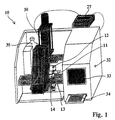
- the synthesis device 10 has a Synthesis module 12, which consists of a first module element 13 and a second module element 14. Between the two The functionalized carrier tape 11 is guided to module elements. For reasons of clarity, the means of transport are for the carrier tape 11 is not shown in Figure 1.
- a pneumatic press 30 that works with the movable interacts first module element 13 and this during implementation one synthesis step against the second one below Module element 14 presses.
- the reaction chambers of the Synthesis module sealed airtight against the environment. With With the help of a filter pressure reducer, the pressure force in set wide limits.
- the first Module element 13 detached from the second module element 14, so that the Tape is released.
- a direct-acting pneumatic press with double-acting cylinder used i.e. the pestle is per in both directions Air pressure moves (Press No. 24, Schmidt Feintechnik GmbH, St. Georgen, Germany).
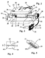
- the device according to the invention is shown in more detail in FIG. 2 shown; there, however, without a carrier tape.
- the synthesis module has one Entry area 28 for the carrier tape and one Exit area 29 on. Downstream of the exit area 29 can be seen traction means from a stepper motor 20 driven roller pair 21 exist.
- the pair of rollers 21 is also somewhat more detailed in a larger one in FIG Scale shown.
- the motor driven roller 22 and the pressure roller 23 are pressed slightly against each other (arrow in Figure 3).
- the carrier tape 11 can be between them are passed through, as in particular from FIG. 3 evident.
- the device 10 is for unidirectional transport of the film strip 11 provided so that at the opposite end of the device, that is, in the vicinity of the entry area 28 of the Carrier tape in the synthesis module 12 a non-driven second pair of rollers 24 is provided as a guide for the belt.
- the second pair of rollers 24 in turn consists of a Pressure roller 25 and a counter roller 26.
- a bidirectional transport could be provided for, either the Roller 25 or roller 26 also with a stepper motor provided, the control unit shown in Figure 1 depending on desired feed direction the actuation of one of the two Motors causes.
- Photoelectric switch 37 checks whether the end of the tape at the entrance 28 of the synthesis module 12 has arrived. Is the carrier tape 11th over, the press 30 is closed and the automatic Control terminates the process. This ensures that a carrier material 11 in the case of unobserved synthesis Synthesis module 12 is located.
- the synthesis module 12 is located between two Steel plates, a base plate 49 and a stop plate 50.
- the first element 13 of the synthesis module 12 is from the pneumatic press 30 actuated. For this purpose, she assigns a guide pin 40 for the press. against the Stop plate 50 comes a (not shown) plunger Press 30 in annex.
- the stop plate 50 is by two Brass slide bearing 38, into which guide pins 48th engage that in the base plate 49 of the synthesis device 10 are anchored.
- the stop plate 50 is in two sets Disc springs 39, which the synthesis module 12 with a force from 2.8 kN open. At an air pressure of 6 bar it will Synthesis module with a resulting force of 5.7 kN (force of the press minus the counterforce of the springs). If that When the synthesis module is open, the carrier tape 11 be transported.
- the front view of a two-part variant of the synthesis module 12 can be seen in FIG. 4.
- the first module element 13 is movable against the second module element 14.
- the two module elements are preferably made of Teflon, so that they are easy to clean and largely chemically inert. A good seal is available when the module elements are pressed together.
- This is supported in particular by the shape shown, in which the upper module element 13 has a projection 41, which in the prototype shown has a height h of 2 mm.
- the projection 41 can be pressed into an incision 42 with a depth d of 1 mm in the second module element 14.
- FIG. 5 shows a perspective view from below of the first module element 13.
- the reaction chambers 15 are recessed in the projection 41.
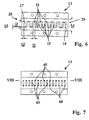
- the reaction chambers 15 can be better seen in the illustration of FIG. 6, which is a bottom view of the module element of FIG. 5.
- the module element has fifteen parallel elongated reaction chambers 15.
- Each reaction channel has a length l1 of approximately 10 mm and a width b2 of 2 mm.
- the width b1 of the projection 41 of the module element 13 is approximately 20 mm.
- connecting channels 31 with a length l2 of 3 mm and a width b3 of 1 mm are provided, each connecting one end of a reaction chamber to the beginning of the subsequent chamber.
- the meandering structure shown arises, so that connecting channels only meet corresponding synthesis fields on the support in every second synthesis step. Even if the connecting channels are therefore open to the wearer, only short-length sequences arise in these areas, which are unproblematic for the respective purpose of the wearer.
- an inlet opening 16 and an outlet opening 17 are provided, which communicate with the automatic synthesizer 32 via the fluid lines 18, 19.
- Fig. 7 shows a further variant of the reaction chambers of the first synthesis module 13.
- the individual reaction chambers 43 are not above Connection channels connected to each other. Rather, everyone points Reaction chamber has its own inlet 44 and its own Outlet 45 on.
- FIG. 8 is a section through the module element 13 of FIG. 7 shown along the line VIII-VIII in Fig. 7.
- the outlets 45 of each chamber 43 via distribution channels 47 in a common collecting channel 46, which in turn through the Fluid line 19 is connected to the automatic synthesizer 32.
- the variant of the module element shown 13 has the advantage that the individual reaction chambers can be flushed faster with the reagents.
- the Production of such a module element with collecting and Distribution channels is particularly easy when it itself is out two subunits is constructed, as in Figure 8 by the different hatching was indicated.
- the control unit 27 consists of a Microcontroller circuit with input keys, display, Motor control, program and data storage and interfaces for press and synthesizer.
- the microcontroller which controls the timing of the synthesis, communicates with the synthesis machine and influences the actuators such as motor and Press. Suitable control software is used for the control created. Program parts are sorted according to their function in divided individual segments.
- Fig. 10 is a typical flow of the automatic Synthesis procedure shown.
- the parameters are the Carrier feed and counter or timer for the process flow. If the machine is started, none in the parameter menus Changes can be made more. This condition is caused by an LED is displayed. The user is now asked close the press and start the synthesizer. The current state of the control unit is now in the Main menu is displayed, in which you can start arrives automatically. With one button you can switch to manual Change process control. In the automatic operating mode however the further process flow through the interaction of Microcontroller and synthesizer automatically controlled.
- Synthesis device 10 can perform parallel synthesis of Oligonucleotides, the sequence of which can be chosen at will, on one Flat carrier, such as a film strip 11, are carried out.
- a four-column device can use four mutually independent, linearly arranged synthesis modules 12 the machine 32 can be connected.
- independent reaction chambers or groups of reaction chambers can be provided within a module.
- the device After completing all four parallel The device according to the invention receives syntheses from the Automatic synthesizer 32 a defined signal, which the Control unit 27 causes the module 12 to open and the To transport the flat carrier 11 as far from the synthesis module, that now each field a new section of the flat beam 11 for Available.
- Automation with the device according to the invention can also on a method for generating sequence overlapping Oligonucleotides are used. With this procedure it is necessary, the flat carrier after each coupling by an exact Transport length further. By using the automatic apparatus, this transport can now be carried out independently be performed. Thus, the synthesis is an arrangement sequentially overlapping oligonucleotides over a longer one Period without further control by the operator of the system possible.
- a Control implemented with a microcontroller.
- Synthesis module 12 which from any, opposite the used inert material chemistry, for example Polytetrafluoroethylene (PTFE).
- the oligomers are on a flat beam 11 (e.g. a functionalized one Polypropylene film) synthesized, which is within the Synthesis module 12 is located.
- the ones necessary for the synthesis chemical steps are carried out on the synthesizer 32 programmed, trigger pulses for the control unit can be delivered.
- the flat beam 11 can automatically be very precise with a motor 20 be positioned. Here was used for transportation Stepper motor used.
- the flat carrier 11 is located between two rollers, one of which has a simple gear is driven by the engine.
Landscapes
- Chemical & Material Sciences (AREA)
- Organic Chemistry (AREA)
- Chemical Kinetics & Catalysis (AREA)
- Apparatus Associated With Microorganisms And Enzymes (AREA)
- Saccharide Compounds (AREA)
- Processing And Handling Of Plastics And Other Materials For Molding In General (AREA)
- Polymerisation Methods In General (AREA)
- Polishing Bodies And Polishing Tools (AREA)
Description
Routinemäßig werden Ansätze im Bereich von ca. 0,2 µMol bis 1 µMol wachsender Ketten im Automaten gefahren.
In neuerer Zeit sind vielfach auch oberflächenfunktionalisierte Flachmaterialien als Träger für parallele Oligonucleotidsynthesen verwendet worden. Hierzu zählen Glasplatten (Maskos, U. and Southern E.M. (1992) Nucleic Acids Res. 20: 1679-1684), Silicium-Wafer (Pease, A.C. et al. Proc. Natl. Acad. Sci. USA 91: 5022-5026), aber auch oberflächenfunktionalisierte Polypropylen-Folien (Matson, R.S. et al. (1994) Analytical Biochemistry 217: 306-310). Die Zielsetzung bei allen diesen Trägerverfahren geht dahin, auf einer gegebenen Trägerfläche eine möglichst große Zahl von "Synthesepunkten" unterzubringen, um damit analytisch / diagnostische Zielsetzungen zu verfolgen.
- Figur 1:
- eine schematische Darstellung einer erfindungsgemäßen Synthesevorrichtung, die an einen kommerziell erhältlichen Syntheseautomaten angeschlossen ist, wobei aus Übersichtsgründen die Transportmittel für das Trägerband nicht dargestellt sind;
- Figur 2:
- eine detailliertere Darstellung der erfindungsgemäßen Synthesevorrichtung aus Figur 1 mit schematisch dargestellten Transportmitteln für das Trägerband;
- Figur 3:
- ein Detail der Transportmittel aus Figur 2;
- Figur 4:
- eine Stirnansicht einer zweiteiligen Ausführungsform des Synthesemoduls der Vorrichtung der Figur 2;
- Figur 5:
- eine perspektivische schematische Darstellung des beweglichen Oberteils des Synthesemoduls der Figur 4;
- Figur 6:
- eine Unteransicht des Moduielementes der Figur 5;
- Figur 7:
- eine der Figur 6 entsprechende Ansicht einer Variante des oberen Modulelementes;
- Figur 8:
- einen Längsschnitt des Modulelementes der Figur 7;
- Figur 9:
- ein beispielhaftes Blockschaltbild, welches die Prozeßautomatisierung der Vorrichtung gemäß Figur 1 verdeutlicht; und
- Figur 10:
- ein beispielhaftes Ablaufdiagramm zur Prozeßsteuerung mit dem Steuergerät gemäß Figur 9.
Claims (16)
- Vorrichtung zur automatischen Synthese von Makromolekülen auf einem bandartigen Trägermaterial (11), mit mindestens einem nach außen abdichtbaren Synthesemodul (12), das wenigstens eine Reaktionskammer (15,43) und Fluidleitungen (18,19,45,46) zum Befüllen und Entleeren der Reaktionskammer (15,43) mit und von Reaktionsmedien umfaßt, wobei das Trägermaterial (11) in das Synthesemodul (12) einführbar ist und mit der Reaktionskammer (15,43) in Kontakt gebracht werden kann, und mit durch eine Steuereinrichtung (27) betätigbaren Transportmitteln (20-26) zum Verschieben des Trägermaterials (11),
dadurch gehennzeichnet, daß
das Synthesemodul (12) mehrere Reaktionskammern (15,43) aufweist, die, in Verschiebungsrichtung des Trägermaterials (11) gesehen, in einem bestimmten Abstand voneinander angeordnet sind, und daß die Steuereinrichtung (27) derart ausgebildet ist, daß das Trägermaterial (11) um eine Wegstrecke verschiebbar ist, die dem Abstand der Reaktionskammern (15,43) voneinander entspricht. - Vorrichtung gemäß Anspruch 1, dadurch gekennzeichnet, daß die Transportmittel ein erstes motorbetriebenes Zugmittel (20-23) umfassen, das nach dem Austrittsbereich (29) des Trägermaterials (11) aus dem Synthesemodul (12) angeordnet ist.
- Vorrichtung gemäß Anspruch 2, dadurch gekennzeichnet, daß die Transportmittel ein zweites motorbetriebenes Zugmittel (24-26) umfassen, das vor dem Eintrittsbereich (28) des Tragermaterials (11) in das Synthesemodul (12) angeordnet ist.
- Vorrichtung gemäß einem der Ansprüche 2 oder 3, dadurch gekennzeichnet, daß jedes Zugmittel einen Schrittmotor (20) aufweist.
- Vorrichtung gemäß einem der Ansprüche 1 bis 4, dadurch gekennzeichnet, daß das Synthesemodul (12) im Ein- und Austrittsbereich (28,29) des Trägerbandes Dichtlippen aufweist.
- Vorrichtung gemäß einem der Ansprüche 1 bis 5, dadurch gekennzeichnet, daß jedes Synthesemodul (12) wenigstens zwei gegeneinander bewegliche Modulelemente (13,14) umfaßt, die jeweils der Ober- und Unterseite des Trägerbandes (11) zugeordnet sind, wobei zumindest ein Modulelement (12) mit einem durch die Steuereinrichtung betätigbaren Stellmittel (30) verbunden ist, welches ein lösbares, dichtes Aneinanderpressen der beiden Modulelemente (13,14) ermöglicht.
- Vorrichtung gemäß Anspruch 6, dadurch gekennzeichnet, daß in beiden Modulelementen (13,14) Reaktionskammern vorgesehen sind.
- Vorrichtung gemäß einem der Ansprüche 6 oder 7, dadurch gekennzeichnet, daß das Stellmittel (30) ein Druckzylinder ist.
- Vorrichtung gemäß einem der vorhergehenden Ansprüche, dadurch gekennzeichnet, daß jede Reaktionskammer (15,43) eine Einlaßöffnung (16) und eine Auslaßöffnung (17) aufweist, über welche die Reaktionskammer mit den Fluidleitungen (18,19,45,46) kommuniziert.
- Vorrichtung gemäß Anspruch 9, dadurch gekennzeichnet, daß zwischen mindestens zwei benachbarten Reaktionskammern (15) ein Verbindungskanal (31) vorgesehen ist.
- Vorrichtung gemäß Anspruch 10, dadurch gekennzeichnet, daß die Reaktionskammern (15) und ihre Verbindungskanäle (31) mäanderförmig angeordnet sind.
- Verwendung der Vorrichtung nach einem der vorhergehenden Ansprüche zur Synthese von auf einem funktionalisierten Trägermaterial gebundenen Oligonucleotiden.
- Verwendung nach Anspruch 12, zur Herstellung von Oligonucleotid-Bibliotheken, insbesondere zur Herstellung von sequenzüberlappenden Oligonucleotid-Bibliotheken.
- Verwendung nach Anspruch 13 zur Herstellung von Diagnostik-Teststreifen.
- Verwendung nach Anspruch 14 zur Herstellung von Teststreifen zur DNA-Sequenzierung.
- Verfahren zur automatischen Synthese von Oligonucleotiden auf einem Trägerband (11) mittels einer Synthesevorrichtung mit einem zumindest zwei Modulelemente (13,14) umfassenden Synthesemodul (12), welches mehrere Reaktionskammern (15,43) aufweist, wobei manund wenigstens einmaldas Tragerband (11) in das Synthesemodul (12) transportiert und dort positioniert,das Synthesemodul (12) durch Zusammenpressen der beiden Modulelemente (13,14) nach außen abdichtet,einen Syntheseschritt mit Hilfe eines üblichen Syntheseautomaten (32) durchführt,anschließend die beiden Elemente (13,14) des Synthesemoduls (12) voneinander löst;wobei der Transport und die Positionierung des Trägerbandes (11), das Zusammenpressen der Modulelemente (13,14), jeder Syntheseschritt und das Lösen der Modulelemente (13,14) durch ein Taktsignal des Syntheseautomaten (30) gesteuert und koordiniert werden.das Trägerband (11) um eine Wegstrecke, die dem Abstand zweier benachbarter Reaktionskammern (15,43) entspricht, weitertransportiert, erneut positioniert und einen weiteren Syntheseschritt durchführt,
Applications Claiming Priority (3)
| Application Number | Priority Date | Filing Date | Title |
|---|---|---|---|
| DE19707000 | 1997-02-21 | ||
| DE19707000 | 1997-02-21 | ||
| PCT/EP1998/001030 WO1998036828A1 (de) | 1997-02-21 | 1998-02-23 | Vorrichtung und verfahren zur automatischen synthese von makromolekülen |
Publications (2)
| Publication Number | Publication Date |
|---|---|
| EP0969919A1 EP0969919A1 (de) | 2000-01-12 |
| EP0969919B1 true EP0969919B1 (de) | 2002-12-04 |
Family
ID=7821104
Family Applications (1)
| Application Number | Title | Priority Date | Filing Date |
|---|---|---|---|
| EP98912374A Expired - Lifetime EP0969919B1 (de) | 1997-02-21 | 1998-02-23 | Vorrichtung und verfahren zur automatischen synthese von makromolekülen |
Country Status (9)
| Country | Link |
|---|---|
| US (1) | US6544775B2 (de) |
| EP (1) | EP0969919B1 (de) |
| JP (1) | JP2001512472A (de) |
| AT (1) | ATE228884T1 (de) |
| DE (1) | DE59806538D1 (de) |
| DK (1) | DK0969919T3 (de) |
| ES (1) | ES2187945T3 (de) |
| PT (1) | PT969919E (de) |
| WO (1) | WO1998036828A1 (de) |
Families Citing this family (7)
| Publication number | Priority date | Publication date | Assignee | Title |
|---|---|---|---|---|
| US5959098A (en) | 1996-04-17 | 1999-09-28 | Affymetrix, Inc. | Substrate preparation process |
| US6706875B1 (en) * | 1996-04-17 | 2004-03-16 | Affyemtrix, Inc. | Substrate preparation process |
| ATE307822T1 (de) * | 1999-11-10 | 2005-11-15 | Merckle Gmbh | Verfahren und vorrichtung zur herstellung von oligomeren und arrays von oligomeren sowie die verwendung der vorrichtung |
| US6649348B2 (en) * | 2001-06-29 | 2003-11-18 | Agilent Technologies Inc. | Methods for manufacturing arrays |
| WO2005058471A2 (en) * | 2003-12-15 | 2005-06-30 | Applera Corporation | Automated oligomer synthesis |
| WO2024137514A1 (en) | 2022-12-22 | 2024-06-27 | Synthego Corporation | Systems and method for automated oligonucleotide synthesis |
| DE102023121082A1 (de) * | 2023-08-08 | 2025-02-13 | Orphan Diagnostics AS | Reaktionskammereinheit und mikrofluidischer Testträger |
Family Cites Families (7)
| Publication number | Priority date | Publication date | Assignee | Title |
|---|---|---|---|---|
| EP0385433A3 (de) * | 1989-02-28 | 1991-08-14 | Ceskoslovenska Akademie Ved | Verfahren und Vorrichtung zur kontinuierlichen Herstellung von Polymeren auf einem festen Träger |
| DE4206488C2 (de) | 1992-03-02 | 1993-12-23 | Deutsches Krebsforsch | Vorrichtung zur Durchführung zeitgleich oder sequentiell ablaufender chemischer Reaktionen |
| US5324483B1 (en) * | 1992-10-08 | 1996-09-24 | Warner Lambert Co | Apparatus for multiple simultaneous synthesis |
| US5554501A (en) * | 1992-10-29 | 1996-09-10 | Beckman Instruments, Inc. | Biopolymer synthesis using surface activated biaxially oriented polypropylene |
| US5429807A (en) | 1993-10-28 | 1995-07-04 | Beckman Instruments, Inc. | Method and apparatus for creating biopolymer arrays on a solid support surface |
| US5585069A (en) | 1994-11-10 | 1996-12-17 | David Sarnoff Research Center, Inc. | Partitioned microelectronic and fluidic device array for clinical diagnostics and chemical synthesis |
| AU1543097A (en) | 1996-01-23 | 1997-08-20 | Novartis Ag | Device and process for the synthetization of macromolecules |
-
1998
- 1998-02-23 JP JP53627898A patent/JP2001512472A/ja not_active Ceased
- 1998-02-23 AT AT98912374T patent/ATE228884T1/de not_active IP Right Cessation
- 1998-02-23 DK DK98912374T patent/DK0969919T3/da active
- 1998-02-23 DE DE59806538T patent/DE59806538D1/de not_active Expired - Fee Related
- 1998-02-23 PT PT98912374T patent/PT969919E/pt unknown
- 1998-02-23 ES ES98912374T patent/ES2187945T3/es not_active Expired - Lifetime
- 1998-02-23 WO PCT/EP1998/001030 patent/WO1998036828A1/de not_active Ceased
- 1998-02-23 EP EP98912374A patent/EP0969919B1/de not_active Expired - Lifetime
- 1998-02-23 US US09/355,974 patent/US6544775B2/en not_active Expired - Fee Related
Also Published As
| Publication number | Publication date |
|---|---|
| WO1998036828A1 (de) | 1998-08-27 |
| PT969919E (pt) | 2003-04-30 |
| ATE228884T1 (de) | 2002-12-15 |
| DK0969919T3 (da) | 2003-03-17 |
| JP2001512472A (ja) | 2001-08-21 |
| DE59806538D1 (de) | 2003-01-16 |
| US6544775B2 (en) | 2003-04-08 |
| ES2187945T3 (es) | 2003-06-16 |
| EP0969919A1 (de) | 2000-01-12 |
| US20010049099A1 (en) | 2001-12-06 |
Similar Documents
| Publication | Publication Date | Title |
|---|---|---|
| EP1101119B1 (de) | Dosierkopf zur parallelen bearbeitung einer vielzahl von fluidproben | |
| DE69418595T2 (de) | Verfahren und vorrichtung zur erzeugung von biopolymermatrizen auf einer festphasenträgeroberfläche | |
| DE4206488C2 (de) | Vorrichtung zur Durchführung zeitgleich oder sequentiell ablaufender chemischer Reaktionen | |
| DE69804653T2 (de) | Verfahren und vorrichtung zur herstellung von matrixen von proben | |
| EP1171232B1 (de) | Fluidhandhabungsvorrichtung mit formatumwandlung | |
| DE19950809B4 (de) | Verfahren und Vorrichtung für eine Flüssigkeitsübertragung | |
| DE60111310T2 (de) | Verfahren, Vorrichtung und Rechnerprogramm zur Herstellung eines Arrays chemischer Vebindungen | |
| DE69927975T2 (de) | Fläschchen und Mehrgefäß rotierende Synthesevorrichtung | |
| DE19917398C2 (de) | Modulares chemisches Mikrosystem | |
| DE69424151T2 (de) | Automatisierte synthese von oligonukleotiden | |
| DE19823719B4 (de) | Verfahren zum Aufkonzentrieren von Substanzen | |
| DE3331257C2 (de) | Vakuumziegelpresse | |
| EP1313551B1 (de) | Vorrichtung und verfahren zum berührungslosen aufbringen von mikrotröpfchen auf ein substrat | |
| DE60012752T2 (de) | Flexibler pipetten-streifen und zugehöriges anwendungsverfahren | |
| EP1759215A1 (de) | Vorrichtung und verfahren zum anordnen von pipetten- oder dispenser-spitzen in einem system zum manipulieren von flüssigkeitsproben | |
| AT405145B (de) | Anordnung und verfahren zur spanlosen bearbeitung von material oder werkstücken | |
| EP0969919A1 (de) | Vorrichtung und verfahren zur automatischen synthese von makromolekülen | |
| WO2004113054A1 (de) | Prägevorrichtung | |
| EP0181491B1 (de) | Vorrichtung zur parallelen Durchführung einer Vielzahl von chemischen Reaktionssequenzen | |
| EP1144106B1 (de) | Vorrichtung zur durchführung von chemischen reaktionen | |
| DE10043345C2 (de) | Vorrichtung zur vollautomatischen Festphasenextraktion | |
| EP3295800A1 (de) | Sandwichkeksvorrichtung | |
| EP1673161A1 (de) | Verfahren und vorrichtung zur durchführung von reaktionen | |
| DE10213977A1 (de) | Verfahren zum Herstellen von Wirkstoffe enthaltenden Formkörpern | |
| DE3446620C2 (de) |
Legal Events
| Date | Code | Title | Description |
|---|---|---|---|
| PUAI | Public reference made under article 153(3) epc to a published international application that has entered the european phase |
Free format text: ORIGINAL CODE: 0009012 |
|
| 17P | Request for examination filed |
Effective date: 19990920 |
|
| AK | Designated contracting states |
Kind code of ref document: A1 Designated state(s): AT BE CH DE DK ES FI FR GB GR IE IT LI LU MC NL PT SE |
|
| 17Q | First examination report despatched |
Effective date: 20000420 |
|
| GRAG | Despatch of communication of intention to grant |
Free format text: ORIGINAL CODE: EPIDOS AGRA |
|
| GRAG | Despatch of communication of intention to grant |
Free format text: ORIGINAL CODE: EPIDOS AGRA |
|
| GRAH | Despatch of communication of intention to grant a patent |
Free format text: ORIGINAL CODE: EPIDOS IGRA |
|
| GRAH | Despatch of communication of intention to grant a patent |
Free format text: ORIGINAL CODE: EPIDOS IGRA |
|
| GRAA | (expected) grant |
Free format text: ORIGINAL CODE: 0009210 |
|
| AK | Designated contracting states |
Kind code of ref document: B1 Designated state(s): AT BE CH DE DK ES FI FR GB GR IE IT LI LU MC NL PT SE |
|
| REF | Corresponds to: |
Ref document number: 228884 Country of ref document: AT Date of ref document: 20021215 Kind code of ref document: T |
|
| REG | Reference to a national code |
Ref country code: GB Ref legal event code: FG4D Free format text: NOT ENGLISH |
|
| REG | Reference to a national code |
Ref country code: CH Ref legal event code: EP |
|
| REG | Reference to a national code |
Ref country code: IE Ref legal event code: FG4D Free format text: GERMAN |
|
| REF | Corresponds to: |
Ref document number: 59806538 Country of ref document: DE Date of ref document: 20030116 |
|
| REG | Reference to a national code |
Ref country code: CH Ref legal event code: NV Representative=s name: BOVARD AG PATENTANWAELTE |
|
| REG | Reference to a national code |
Ref country code: DK Ref legal event code: T3 |
|
| REG | Reference to a national code |
Ref country code: GR Ref legal event code: EP Ref document number: 20030400715 Country of ref document: GR |
|
| ET | Fr: translation filed | ||
| GBT | Gb: translation of ep patent filed (gb section 77(6)(a)/1977) |
Effective date: 20030404 |
|
| REG | Reference to a national code |
Ref country code: PT Ref legal event code: SC4A Free format text: AVAILABILITY OF NATIONAL TRANSLATION Effective date: 20030228 |
|
| REG | Reference to a national code |
Ref country code: ES Ref legal event code: FG2A Ref document number: 2187945 Country of ref document: ES Kind code of ref document: T3 |
|
| PLBE | No opposition filed within time limit |
Free format text: ORIGINAL CODE: 0009261 |
|
| STAA | Information on the status of an ep patent application or granted ep patent |
Free format text: STATUS: NO OPPOSITION FILED WITHIN TIME LIMIT |
|
| 26N | No opposition filed |
Effective date: 20030905 |
|
| PGFP | Annual fee paid to national office [announced via postgrant information from national office to epo] |
Ref country code: ES Payment date: 20080229 Year of fee payment: 11 Ref country code: DK Payment date: 20080229 Year of fee payment: 11 Ref country code: CH Payment date: 20080228 Year of fee payment: 11 |
|
| PGFP | Annual fee paid to national office [announced via postgrant information from national office to epo] |
Ref country code: SE Payment date: 20080228 Year of fee payment: 11 Ref country code: PT Payment date: 20080221 Year of fee payment: 11 Ref country code: NL Payment date: 20080229 Year of fee payment: 11 Ref country code: MC Payment date: 20080228 Year of fee payment: 11 Ref country code: LU Payment date: 20080303 Year of fee payment: 11 Ref country code: IT Payment date: 20080228 Year of fee payment: 11 Ref country code: IE Payment date: 20080228 Year of fee payment: 11 Ref country code: GB Payment date: 20080220 Year of fee payment: 11 Ref country code: FI Payment date: 20080229 Year of fee payment: 11 Ref country code: DE Payment date: 20080221 Year of fee payment: 11 |
|
| PGFP | Annual fee paid to national office [announced via postgrant information from national office to epo] |
Ref country code: AT Payment date: 20080228 Year of fee payment: 11 |
|
| PGFP | Annual fee paid to national office [announced via postgrant information from national office to epo] |
Ref country code: FR Payment date: 20080226 Year of fee payment: 11 |
|
| PGFP | Annual fee paid to national office [announced via postgrant information from national office to epo] |
Ref country code: BE Payment date: 20080422 Year of fee payment: 11 |
|
| PGFP | Annual fee paid to national office [announced via postgrant information from national office to epo] |
Ref country code: GR Payment date: 20080228 Year of fee payment: 11 |
|
| BERE | Be: lapsed |
Owner name: *MERCKLE G.M.B.H. Effective date: 20090228 |
|
| REG | Reference to a national code |
Ref country code: PT Ref legal event code: MM4A Free format text: LAPSE DUE TO NON-PAYMENT OF FEES Effective date: 20090824 |
|
| PG25 | Lapsed in a contracting state [announced via postgrant information from national office to epo] |
Ref country code: MC Free format text: LAPSE BECAUSE OF NON-PAYMENT OF DUE FEES Effective date: 20090228 |
|
| REG | Reference to a national code |
Ref country code: CH Ref legal event code: PL |
|
| EUG | Se: european patent has lapsed | ||
| REG | Reference to a national code |
Ref country code: DK Ref legal event code: EBP |
|
| GBPC | Gb: european patent ceased through non-payment of renewal fee |
Effective date: 20090223 |
|
| PG25 | Lapsed in a contracting state [announced via postgrant information from national office to epo] |
Ref country code: PT Free format text: LAPSE BECAUSE OF NON-PAYMENT OF DUE FEES Effective date: 20090824 Ref country code: LI Free format text: LAPSE BECAUSE OF NON-PAYMENT OF DUE FEES Effective date: 20090228 Ref country code: FI Free format text: LAPSE BECAUSE OF NON-PAYMENT OF DUE FEES Effective date: 20090223 Ref country code: CH Free format text: LAPSE BECAUSE OF NON-PAYMENT OF DUE FEES Effective date: 20090228 Ref country code: AT Free format text: LAPSE BECAUSE OF NON-PAYMENT OF DUE FEES Effective date: 20090223 |
|
| NLV4 | Nl: lapsed or anulled due to non-payment of the annual fee |
Effective date: 20090901 |
|
| REG | Reference to a national code |
Ref country code: IE Ref legal event code: MM4A |
|
| REG | Reference to a national code |
Ref country code: FR Ref legal event code: ST Effective date: 20091030 |
|
| PG25 | Lapsed in a contracting state [announced via postgrant information from national office to epo] |
Ref country code: NL Free format text: LAPSE BECAUSE OF NON-PAYMENT OF DUE FEES Effective date: 20090901 |
|
| PG25 | Lapsed in a contracting state [announced via postgrant information from national office to epo] |
Ref country code: IE Free format text: LAPSE BECAUSE OF NON-PAYMENT OF DUE FEES Effective date: 20090223 Ref country code: DE Free format text: LAPSE BECAUSE OF NON-PAYMENT OF DUE FEES Effective date: 20090901 |
|
| PG25 | Lapsed in a contracting state [announced via postgrant information from national office to epo] |
Ref country code: BE Free format text: LAPSE BECAUSE OF NON-PAYMENT OF DUE FEES Effective date: 20090228 Ref country code: GR Free format text: LAPSE BECAUSE OF NON-PAYMENT OF DUE FEES Effective date: 20090902 |
|
| REG | Reference to a national code |
Ref country code: ES Ref legal event code: FD2A Effective date: 20090224 |
|
| PG25 | Lapsed in a contracting state [announced via postgrant information from national office to epo] |
Ref country code: GB Free format text: LAPSE BECAUSE OF NON-PAYMENT OF DUE FEES Effective date: 20090223 Ref country code: FR Free format text: LAPSE BECAUSE OF NON-PAYMENT OF DUE FEES Effective date: 20090302 |
|
| PG25 | Lapsed in a contracting state [announced via postgrant information from national office to epo] |
Ref country code: ES Free format text: LAPSE BECAUSE OF NON-PAYMENT OF DUE FEES Effective date: 20090224 Ref country code: DK Free format text: LAPSE BECAUSE OF NON-PAYMENT OF DUE FEES Effective date: 20090831 |
|
| PG25 | Lapsed in a contracting state [announced via postgrant information from national office to epo] |
Ref country code: IT Free format text: LAPSE BECAUSE OF NON-PAYMENT OF DUE FEES Effective date: 20090223 |
|
| PG25 | Lapsed in a contracting state [announced via postgrant information from national office to epo] |
Ref country code: LU Free format text: LAPSE BECAUSE OF NON-PAYMENT OF DUE FEES Effective date: 20090223 |
|
| PG25 | Lapsed in a contracting state [announced via postgrant information from national office to epo] |
Ref country code: SE Free format text: LAPSE BECAUSE OF NON-PAYMENT OF DUE FEES Effective date: 20090224 |