EP0969356A2 - Pufferverwaltungssystem und -Verfahren, Frei-Zeiger-FIFOs benutzend, die Zeiger zu leeren Puffern enthalten - Google Patents
Pufferverwaltungssystem und -Verfahren, Frei-Zeiger-FIFOs benutzend, die Zeiger zu leeren Puffern enthalten Download PDFInfo
- Publication number
- EP0969356A2 EP0969356A2 EP99304801A EP99304801A EP0969356A2 EP 0969356 A2 EP0969356 A2 EP 0969356A2 EP 99304801 A EP99304801 A EP 99304801A EP 99304801 A EP99304801 A EP 99304801A EP 0969356 A2 EP0969356 A2 EP 0969356A2
- Authority
- EP
- European Patent Office
- Prior art keywords
- buffer
- data
- buffers
- buffer pointer
- available
- Prior art date
- Legal status (The legal status is an assumption and is not a legal conclusion. Google has not performed a legal analysis and makes no representation as to the accuracy of the status listed.)
- Withdrawn
Links
Images
Classifications
-
- G—PHYSICS
- G06—COMPUTING OR CALCULATING; COUNTING
- G06F—ELECTRIC DIGITAL DATA PROCESSING
- G06F5/00—Methods or arrangements for data conversion without changing the order or content of the data handled
- G06F5/06—Methods or arrangements for data conversion without changing the order or content of the data handled for changing the speed of data flow, i.e. speed regularising or timing, e.g. delay lines, FIFO buffers; over- or underrun control therefor
- G06F5/065—Partitioned buffers, e.g. allowing multiple independent queues, bidirectional FIFO's
Definitions
- the invention relates generally to the field of digital systems, such as digital computer systems, digital communication systems and the like, more particularly to arrangements for managing buffers which are used to store data.
- the buffers may be used, for example, to temporarily store data received from one element of the system prior to being transferred to another element of the system.
- a source may comprise a process in which data to be transferred to a storage device local to the digital computer system or to another digital computer system, is generated and organized for transmission
- a destination may comprise a process in which the data from the source retrieves the data and actually performs the transfer.
- the source will provide the data to destination through a buffering arrangement, in which the source stores the data that it generates in an buffer store intermediate the source and destination, from which the destination will retrieve the data for transmission.
- Storing the data to be transferred in such a buffering arrangement allows the source and destination to operate at different instantaneous rates, irrespective of the rate at which the other is operating.
- multiple sources are providing data for transfer through a single destination, they can all use the same buffering arrangement to provide data to the destination, and, similarly, if a single source is providing data for transfer through multiple destinations, it can use a single buffering arrangement to provide data to all of the destinations.
- a number of buffers are organized in one or more linked lists.
- the data associated with, for example, a source or a destination is stored in a buffer or a series of buffers, with each buffers in a series including pointers which point to the next buffer in the series.
- a free list is provided with empty buffers, which can be allocated to the lists for the respective sources or destinations when data to be buffered is received in the buffering arrangement.
- an empty buffer from the free list is allocated for the data, by delinking it from the free list and linking it to the list associated with the source or destination, after which the data can be stored in the newly-allocated buffer.
- the destination retrieves data from a linked list, it retrieves the data from the respective buffers and thereafter links the data from which the buffers have been retrieved to the free list. Both of these processes require manipulating pointers in both the free list and the list associated with the source and destination.
- linked lists While the use of linked lists is effective, it can be inefficient, particularly in connection with relatively small buffers.
- the pointers which are used to organize the linked lists take up space in the buffers.
- manipulating the pointers when a buffer is allocated to one of the lists when data is received for storage, or returned to the free list when the data is retrieved by a destination can take some time to perform.
- first and second aspects of the invention there is provided a system and method for allocating buffers in a digital data processing system from a pool of empty buffers, for example using one or more FIFOs, which contain pointers to empty buffers.
- a buffer management subsystem is arranged to receive data from one or more source processes for transfer to one or more destination processes.
- the buffer management subsystem includes a buffer memory and a buffer pointer FIFO that is associated with one of the destination processes.
- the buffer pointer FIFO stores pointers to buffers in the buffer memory which are available to be used to store data from the source process(es) for transfer to the respective associated destination process.
- a buffer pointer is retrieved from the buffer pointer FIFO associated with the destination process and used in storing the data in the buffer pointed to by the buffer pointer.
- the buffer pointer to the buffer is returned to the buffer pointer FIFO.
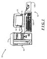
- FIG. 1 depicts an illustrative computer system 10 including a buffer management subsystem constructed in accordance with an embodiment of the invention
- the computer system 10 in one embodiment includes a processor module 11 and operator interface elements comprising operator input components such as a keyboard 12A and/or a mouse 12B (generally identified as operator input element(s) 12) and operator output components such as a video display device 13 with integral speakers 15.
- the illustrative computer system 10 is of the conventional stored-program computer architecture.
- the processor module 11 includes, for example, processor, memory and mass storage devices such as disk and/or tape storage elements (not separately shown) which perform processing and storage operations in connection with digital data provided thereto.
- the mass storage subsystems may include such devices as disk or tape subsystems, optical disk storage devices and CD-ROM devices in which information may be stored and/or from which information may be retrieved.
- One or more of the mass storage subsystems may utilize removable storage media which may be removed and installed by an operator, which may allow the operator to load programs and data into the digital computer system 10 and obtain processed data therefrom. Under control of control information provided thereto by the processor, information stored in the mass storage subsystems may be transferred to the memory for storage. After the information is stored in the memory, the processor may retrieve it from the memory for processing. After the processed data is generated, the processor may also enable the mass storage subsystems to retrieve the processed data from the memory for relatively long-term storage.
- the operator input element(s) 12 are provided to permit an operator to input information for processing and/or control of the digital computer system 10.
- the video display device 13 and speakers 15 are provided to, respectively, display visual output information on a screen 14, and audio output information, which are generated by the processor module 11, which may include data that the operator may input for processing, information that the operator may input to control processing, as well as information generated during processing.
- the processor module 11 generates information for display by the video display device 13 using a so-called “graphical user interface” ("GUI”), in which information for various applications programs is displayed using various "windows.”
- GUI graphical user interface
- the computer system 10 is shown as comprising particular components, such as the keyboard 12A and mouse 12B for receiving input information from an operator, and a video display device 13 for displaying output information to the operator, it will be appreciated that the computer system 10 may include a variety of components in addition to or instead of those depicted in FIG. 1.
- the processor module 11 may include one or more network or communication ports, generally identified by reference numeral 15, which can be connected to communication links to connect the computer system 10 in a computer network, or to other computer systems (not shown) over, for example, the public telephony system.
- the ports enable the computer system 10 to transmit information to, and receive information from, other computer systems and other devices in the network.
- the buffer management subsystem useful in the digital computer system 10 depicted in FIG. 1, to facilitate buffering of data received from one or more source processes which is to be provided to one or more destination processes.
- the buffer management subsystem is used in a communications subsystem to buffer data received from one or more source processes for retrieval by one or more destination processes.
- the source processes can generate data to be transferred for local storage on one or more storage devices, such as disk storage devices or the like, which are maintained by the digital computer system 10 itself.
- the source processes can generate data to be transferred through a network port 15 over a network (not shown) for remote storage.
- the destination processes retrieve the data from the buffer management subsystem to perform the transfer, with one of the destination processes control the transfer for local storage and another of the destination processes controlling the transfer for remote storage.
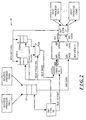
- FIG. 2 depicts a buffer management subsystem 20.
- the buffer management subsystem 20 includes an input FIFO (first in-first out buffer) 21 which receives data from one or more source processes 22(1) through 22(N) (generally identified by reference numeral 22(n)) for transfer to one or more destination processes 23(1) through 23(M) (generally identified by reference numeral 23(m)).
- Data from the input FIFO 21 is transferred to a buffer memory 24 for buffer storage prior to being retrieved by the destination processes for transfer.
- the buffer memory 24 comprises a plurality of storage locations organized into a number of buffers (not separately shown). Each buffer comprises a series of storage locations in the buffer memory 24 from a storage location identified by a base address.
- Each of the buffers is associated with one of the destination processes 23(m), so that data received from a source process 22(n) for transfer to a destination process 23(m) will be stored in one of the buffers associated with that destination process 23(m).
- the buffer management subsystem 20 further has a number of FIFOs 25(1) through 25(M) (generally identified by reference numeral 25(m)), each of which is associated with a correspondingly-indexed one of the destination processes 23(m) and provides storage for buffer pointers pointing to buffers in the buffer memory 24 into which data from the input FIFO 21 for the associated destination process. Each buffer pointer points to the base address for the respective buffer in the buffer memory 24.
- the buffer pointer FIFO 25(m) associated with the destination process 23(m) will not contain a pointer to the buffer in which the data is stored, so that the input control module 26 will not re-use the buffer until the data has been retrieved by the output control module 27.
- the input control module 26 when the input control module 26 enables data to be transferred from the input FIFO 21 to the buffer memory 24 for buffer storage, it will initially identify the destination process 23(m) to which the data is to be transferred and generate a DEST PROC SEL destination process select signal indicative thereof.
- the DEST PROC SEL signal enables the one of the buffer pointer FIFOs 25(m) associated with the destination process 23(m) to provide a buffer pointer to one input of a multiplexer 30.
- the DEST PROC SEL signal also enables the multiplexer 30 to couple the buffer pointer provided by the buffer pointer FIFO 25(m) associated with the destination process 23(m) as a BUF BASE buffer base signal to one input of an address generator 31.
- the input control module 26 will enable the input FIFO 21 to transfer the data to buffer memory as WR DATA write data signals.
- the input control module 26 will provide BUF OFFSET buffer offset signals which the address generator 31 will use, along with the BUF BASE signal, in generating a WR_ADRS write address signal to identify the storage location in the buffer memory 24 in which the data represented by the WR DATA write data signal is to be stored.
- the input control module 26 will generate the BUF OFFSET buffer offset signal so as to identify successive storage locations in the buffer memory 24 comprising the buffer pointed to by the BUF BASE signal.
- the input control module 26 After the input control module 26 has enabled the data to be stored in the buffer, it will enable the FIFO 25(m) associated with the destination process 23(m) to advance to the next pointer, if any, which is stored therein, in which case the pointer that was used to provide the BUF BASE signal will no longer be in the FIFO 25(m).
- the output control module 27 in response to a request from a destination process 23(m) to retrieve data from the buffer memory 24 for transfer to the destination process 23(m), it will provide a RD_ADRS read address signal identifying storage locations in the buffer memory 24 for a buffer associated with the destination process 23(m), generally starting from the first location for the buffer in the buffer memory 24.
- the buffer memory 24 will, in response, provide a RD DATA signal comprising the data from the storage location identified by the RD_ADRS signal, which, in turn, the output control module 27 will provide to the destination process 23(m).
- the output control module will generate a PTR_RETURN pointer return signal, comprising the buffer pointer for the buffer from which data was just retrieved, which it loads into the FIFO 25(m) associated with the destination process for which the data was just retrieved.
- a buffer management subsystem 20 in which buffers associated with respective destination processes can be managed in a relatively simple manner, by storing buffer pointers for buffers in which data can be stored in a FIFO, instead of more complex arrangements such as linked lists and the like.
- the buffer management subsystem 20 may be used in connection with a single source process and/or a single destination process. If the buffer management subsystem 20 is used with a single destination process, it will be appreciated that a single buffer pointer FIFO 25(m) will be provided, in which case the multiplexer 30 may be omitted.
- each destination process can connect directly to the buffer memory and retrieve data therefrom. In that case, each destination process 23(m), after it retrieves data from a buffer, will load the buffer pointer for the buffer in the buffer pointer FIFO 25(m) associated therewith.
- the buffer management subsystem 20 has been described such that the buffer pointer for a buffer from which data is being retrieved will be loaded into the buffer pointer FIFO 25(m) after all of the data has been retrieved from the buffer, it will be appreciated that the buffer pointer may be loaded into the buffer pointer FIFO 25(m) at an earlier time, which can allow the input control module 26 to begin loading data into the buffer while the previously-loaded data is being retrieved from the buffer.
- the loading of the buffer pointer in the respective buffer pointer FIFO 25(m) until some time after the data has been retrieved from the respective buffer, for example, after an acknowledgment has been received from a downstream process indicating receipt of the retrieved data.
- the input control module 26 when it is to transfer data from the input FIFO 21 into a buffer associated with a particular destination process 23(m) determines that there are no buffer pointers in the buffer pointer FIFO 25(m) associated with the destination process 23(m), it can either stall until a buffer pointer is available, discard the data, or process other data for a destination process 23(m) for which a buffer pointer is available in the FIFO 25(m) associated therewith.
- buffer management subsystem 20 has been described as using FIFOs 25(m) to store buffer pointers for buffers that are associated with the respective destination processes 23(m), it will be appreciated that other mechanisms, such as stacks (last in-first out) mechanisms can be used.
- each FIFO may instead be associated with one of the source processes 22(n), or for respective pairs of source and destination processes.
- a system in accordance with embodiments of the invention can be constructed in whole or in part from special purpose hardware or a general purpose computer system, or any combination thereof, any portion of which may be controlled by a suitable program.
- Any program may in whole or in part comprise part of or be stored on the system in a conventional manner, or it may in whole or in part be provided in to the system over a network or other mechanism for transferring information in a conventional manner.
- the system may be operated and/or otherwise controlled by means of information provided by an operator using operator input elements (not shown) which may be connected directly to the system or which may transfer the information to the system over a network or other mechanism for transferring information in a conventional manner.
Landscapes
- Engineering & Computer Science (AREA)
- Theoretical Computer Science (AREA)
- Physics & Mathematics (AREA)
- General Engineering & Computer Science (AREA)
- General Physics & Mathematics (AREA)
- Computer And Data Communications (AREA)
- Communication Control (AREA)
- Multi Processors (AREA)
Applications Claiming Priority (2)
| Application Number | Priority Date | Filing Date | Title |
|---|---|---|---|
| US108918 | 1993-01-19 | ||
| US09/108,918 US6347348B1 (en) | 1998-06-30 | 1998-06-30 | Buffer management system having an output control configured to retrieve data in response to a retrieval request from a requesting one of a plurality of destinations |
Publications (2)
| Publication Number | Publication Date |
|---|---|
| EP0969356A2 true EP0969356A2 (de) | 2000-01-05 |
| EP0969356A3 EP0969356A3 (de) | 2001-02-14 |
Family
ID=22324805
Family Applications (1)
| Application Number | Title | Priority Date | Filing Date |
|---|---|---|---|
| EP99304801A Withdrawn EP0969356A3 (de) | 1998-06-30 | 1999-06-18 | Pufferverwaltungssystem und -Verfahren, Frei-Zeiger-FIFOs benutzend, die Zeiger zu leeren Puffern enthalten |
Country Status (4)
| Country | Link |
|---|---|
| US (1) | US6347348B1 (de) |
| EP (1) | EP0969356A3 (de) |
| JP (1) | JP2000090042A (de) |
| KR (1) | KR20000006575A (de) |
Families Citing this family (6)
| Publication number | Priority date | Publication date | Assignee | Title |
|---|---|---|---|---|
| JP2001306532A (ja) * | 2000-04-19 | 2001-11-02 | Internatl Business Mach Corp <Ibm> | データ処理装置およびマルチプロセッサ装置 |
| US7689793B1 (en) | 2003-05-05 | 2010-03-30 | Marvell Israel (M.I.S.L.) Ltd. | Buffer management architecture |
| US20060143334A1 (en) * | 2004-12-29 | 2006-06-29 | Naik Uday R | Efficient buffer management |
| US7668186B1 (en) * | 2006-03-07 | 2010-02-23 | Xilinx, Inc. | Token ecosystem for buffer management |
| US8433859B2 (en) * | 2008-11-25 | 2013-04-30 | Mediatek Inc. | Apparatus and method for buffer management for a memory operating |
| JP4886887B2 (ja) | 2010-07-23 | 2012-02-29 | 株式会社東芝 | コマンド管理装置及び同コマンド管理装置を備えた記憶装置 |
Family Cites Families (6)
| Publication number | Priority date | Publication date | Assignee | Title |
|---|---|---|---|---|
| US4715030A (en) * | 1986-08-04 | 1987-12-22 | General Electric Company | Local area network bridge |
| CA2028329C (en) * | 1989-10-23 | 2000-01-18 | Hideaki Yamanaka | Cell exchanging apparatus |
| JPH06276214A (ja) * | 1993-03-18 | 1994-09-30 | Hitachi Ltd | Stm信号とatm信号の混在処理方法およびスイッチシステム |
| US5506747A (en) * | 1994-12-15 | 1996-04-09 | Northern Telecom Limited | Provision of FIFO buffer in RAM |
| US5812775A (en) * | 1995-07-12 | 1998-09-22 | 3Com Corporation | Method and apparatus for internetworking buffer management |
| US5778180A (en) * | 1995-11-06 | 1998-07-07 | Sun Microsystems, Inc. | Mechanism for reducing data copying overhead in protected memory operating systems |
-
1998
- 1998-06-30 US US09/108,918 patent/US6347348B1/en not_active Expired - Lifetime
-
1999
- 1999-06-18 EP EP99304801A patent/EP0969356A3/de not_active Withdrawn
- 1999-06-23 JP JP17652399A patent/JP2000090042A/ja active Pending
- 1999-06-30 KR KR1019990025901A patent/KR20000006575A/ko not_active Withdrawn
Also Published As
| Publication number | Publication date |
|---|---|
| US6347348B1 (en) | 2002-02-12 |
| EP0969356A3 (de) | 2001-02-14 |
| JP2000090042A (ja) | 2000-03-31 |
| KR20000006575A (ko) | 2000-01-25 |
Similar Documents
| Publication | Publication Date | Title |
|---|---|---|
| US5640544A (en) | Computer network having an asynchronous document data management system | |
| US5038277A (en) | Adjustable buffer for data communications in a data processing system | |
| US5682553A (en) | Host computer and network interface using a two-dimensional per-application list of application level free buffers | |
| JP2950432B2 (ja) | 複数データ・ストリームおよび実時間タスクの同期およびスケジューリングの方法および装置 | |
| CA2284947C (en) | Apparatus and method for managing data storage | |
| EP0118446A1 (de) | Fifo-speicherkonfiguration für warteschlangenspeicherung. | |
| KR19990029323A (ko) | 애플리케이션 프로그램 인터페이스와 이를 구현하는 방법 및 컴퓨터 프로그램 제품 | |
| EP0374338B1 (de) | Gemeinsamer intelligenter Speicher für die gegenseitige Verbindung von verteilten Mikroprozessoren | |
| US6223243B1 (en) | Access control method with plural users having I/O commands prioritized in queues corresponding to plural memory units | |
| US11122002B2 (en) | Storing messages of a message queue | |
| US6347348B1 (en) | Buffer management system having an output control configured to retrieve data in response to a retrieval request from a requesting one of a plurality of destinations | |
| US5765041A (en) | System for triggering direct memory access transfer of data between memories if there is sufficient data for efficient transmission depending on read write pointers | |
| US8392636B2 (en) | Virtual multiple instance extended finite state machines with wait rooms and/or wait queues | |
| US5666546A (en) | Method of managing concurrent accesses to a memory by a plurality of users using atomic instructions to prevent read/write errors | |
| US20060047874A1 (en) | Resource management apparatus | |
| US5706513A (en) | System and method for queuing an retrieving data objects to and from a shared storage medium | |
| US5706512A (en) | Computer program product for queuing and retrieving data objects to and from a shared storage medium | |
| EP0141753B1 (de) | Anpassbarer Puffer für Datenübertragung in einem Datenverarbeitungssystem | |
| JPH09179970A (ja) | イメージ処理システム | |
| JPS59151252A (ja) | 画像検索装置 | |
| US20220020407A1 (en) | Semiconductor device | |
| JP3068427B2 (ja) | メッセージ制御装置 | |
| US7203518B2 (en) | Method and apparatus for simplified data dispensation to and from digital systems | |
| JPH1051469A (ja) | Atmスイッチ | |
| JPH0833869B2 (ja) | データ処理装置 |
Legal Events
| Date | Code | Title | Description |
|---|---|---|---|
| PUAI | Public reference made under article 153(3) epc to a published international application that has entered the european phase |
Free format text: ORIGINAL CODE: 0009012 |
|
| AK | Designated contracting states |
Kind code of ref document: A2 Designated state(s): DE FR GB NL |
|
| AX | Request for extension of the european patent |
Free format text: AL;LT;LV;MK;RO;SI |
|
| PUAL | Search report despatched |
Free format text: ORIGINAL CODE: 0009013 |
|
| AK | Designated contracting states |
Kind code of ref document: A3 Designated state(s): AT BE CH CY DE DK ES FI FR GB GR IE IT LI LU MC NL PT SE |
|
| AX | Request for extension of the european patent |
Free format text: AL;LT;LV;MK;RO;SI |
|
| 17P | Request for examination filed |
Effective date: 20010731 |
|
| AKX | Designation fees paid |
Free format text: DE FR GB NL |
|
| 17Q | First examination report despatched |
Effective date: 20030122 |
|
| RAP1 | Party data changed (applicant data changed or rights of an application transferred) |
Owner name: SUN MICROSYSTEMS, INC. |
|
| STAA | Information on the status of an ep patent application or granted ep patent |
Free format text: STATUS: THE APPLICATION IS DEEMED TO BE WITHDRAWN |
|
| 18D | Application deemed to be withdrawn |
Effective date: 20030802 |