EP0968340B1 - Support de tuyau - Google Patents
Support de tuyau Download PDFInfo
- Publication number
- EP0968340B1 EP0968340B1 EP97950554A EP97950554A EP0968340B1 EP 0968340 B1 EP0968340 B1 EP 0968340B1 EP 97950554 A EP97950554 A EP 97950554A EP 97950554 A EP97950554 A EP 97950554A EP 0968340 B1 EP0968340 B1 EP 0968340B1
- Authority
- EP
- European Patent Office
- Prior art keywords
- holder
- pipe
- end portion
- engagement
- hooks
- Prior art date
- Legal status (The legal status is an assumption and is not a legal conclusion. Google has not performed a legal analysis and makes no representation as to the accuracy of the status listed.)
- Expired - Lifetime
Links
- 230000000694 effects Effects 0.000 claims description 6
- 210000002105 tongue Anatomy 0.000 claims description 6
- 239000002184 metal Substances 0.000 claims description 2
- 230000006978 adaptation Effects 0.000 description 1
- 238000006073 displacement reaction Methods 0.000 description 1
- 239000007788 liquid Substances 0.000 description 1
- 230000007704 transition Effects 0.000 description 1
Images

Classifications
-
- E—FIXED CONSTRUCTIONS
- E04—BUILDING
- E04D—ROOF COVERINGS; SKY-LIGHTS; GUTTERS; ROOF-WORKING TOOLS
- E04D13/00—Special arrangements or devices in connection with roof coverings; Protection against birds; Roof drainage ; Sky-lights
- E04D13/04—Roof drainage; Drainage fittings in flat roofs, balconies or the like
- E04D13/08—Down pipes; Special clamping means therefor
-
- F—MECHANICAL ENGINEERING; LIGHTING; HEATING; WEAPONS; BLASTING
- F16—ENGINEERING ELEMENTS AND UNITS; GENERAL MEASURES FOR PRODUCING AND MAINTAINING EFFECTIVE FUNCTIONING OF MACHINES OR INSTALLATIONS; THERMAL INSULATION IN GENERAL
- F16L—PIPES; JOINTS OR FITTINGS FOR PIPES; SUPPORTS FOR PIPES, CABLES OR PROTECTIVE TUBING; MEANS FOR THERMAL INSULATION IN GENERAL
- F16L3/00—Supports for pipes, cables or protective tubing, e.g. hangers, holders, clamps, cleats, clips, brackets
- F16L3/08—Supports for pipes, cables or protective tubing, e.g. hangers, holders, clamps, cleats, clips, brackets substantially surrounding the pipe, cable or protective tubing
- F16L3/12—Supports for pipes, cables or protective tubing, e.g. hangers, holders, clamps, cleats, clips, brackets substantially surrounding the pipe, cable or protective tubing comprising a member substantially surrounding the pipe, cable or protective tubing
-
- E—FIXED CONSTRUCTIONS
- E04—BUILDING
- E04D—ROOF COVERINGS; SKY-LIGHTS; GUTTERS; ROOF-WORKING TOOLS
- E04D13/00—Special arrangements or devices in connection with roof coverings; Protection against birds; Roof drainage ; Sky-lights
- E04D13/04—Roof drainage; Drainage fittings in flat roofs, balconies or the like
- E04D13/08—Down pipes; Special clamping means therefor
- E04D2013/084—Means for fixing down pipes to structure
Definitions
- the present invention relates to a holder for pipes, especially downpipes, and more specifically concerns a pipe holder of the type as defined in the preamble to claim 1 as based on CH-643 338.
- FR-A-2,071,357 which in Figs 1-2 shows a holder made of plastic and adapted to encompass plastic pipes through which liquids having different temperatures flow.
- the annular holder has on its inside a number of projections.
- This prior-art holder is not intended for downpipes, and also the French document does not discuss any of the problems involved in pipe holders where the present invention may be applied.
- the object of the invention is to provide a pipe holder which is improved over prior art and which allows more rational mounting and simplified handling.
- the pipe holder according to the invention is extremely advantageous by being attachable to the pipe with simple operations and without requiring any tool, which implies a considerable rationalisation compared to prior art.
- the new pipe holder is fixed to the pipe by a simple clamping and snap action, which besides in a preferred embodiment allows an intermediate position, in which the pipe holder can be moved along the pipe.
- a special advantage is that the invention is generally applicable to many types of pipe holders independently of the appearance of their fastening means.
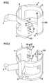
- Figs 1-2 show a pipe holder according to an embodiment of an invention, which comprises a cylindrical and circumferentially resilient body, which is made in one piece and which is referred to as pipe clamp 1. From the pipe clamp 1 project fastening means which in this embodiment have the form of two legs 2, 3 with fixing holes for mounting on a wall, as illustrated in Fig. 3 where two fixing screws 5 are schematically shown.
- the pipe clamp 1 which is adapted to grasp a pipe 6, preferably a downpipe, which is indicated by dashed lines in Fig. 3, comprises two substantially semicircular parts 7, 8, which are interconnected via a rear portion 9 which extends axially, i.e. in parallel with the centre axis of the pipe clamp 1, and thus in the mounting position in parallel with the centre axis of the pipe 6.
- the pipe clamp part 7 has an end portion 10 which, in respect of the circumferential direction of the pipe clamp 1, is positioned opposite to an end portion 11 of the pipe clamp part 8.
- the pipe clamp parts 7, 8 have a spring-back effect, implying that they essentially return to the position shown in Fig. 1 if the spaced-apart end portions 10, 11 are moved closer together or if they are slightly separated.
- the two end portions 10, 11 are, in respect of the circumferential direction of the pipe clamp 1, positioned essentially diametrically opposite to the rear portion 9, from which the legs 2, 3 project. This makes the pipe clamp 1 symmetrical, which promotes its resilient effect, as will be described in more detail below.
- the end portion 10 of the part 7 has engagement means in the form of two axially spaced-apart tongues 12 which are adapted to engage corresponding engagement means arranged in the end portion 11 of the part 8 and being in the form of an axial edge portion with elongate hooks 13 for engaging the tongues 12.
- Each tongue 12 has in its transition to the pipe clamp body two opposite recesses 14, 15, from which two protruding flanges 16, 17 extend in the direction of the free end of the tongue 12.
- Each flange 16, 17 has an inner hook portion 18 and an outer hook portion 19, as is best seen from Fig. 2.
- pipe clamp part 8 has at its end an axial curved portion 20, which in respect of the pipe clamp 1 is curved outwards and which will be described in more detail below.
- the pipe holder is mounted by its legs 2, 3 being screwed to the vertical wall 4 by means of the fixing screws 5. Then the pipe 6 is placed inside the pipe clamp 1 such that the resilient pipe clamp parts 7, 8 grasp the pipe 6.
- the pipe 6 is placed in the pipe clamp 1 either by being inserted axially into the same or by the pipe clamp parts 7, 8 being expanded and the pipe 6 being moved into the gap between the end portions 10, 11 (cf. Fig. 3).
- the fitter then closes by hand the pipe clamp 1 by moving the end portion 11 of the part 8 into snap engagement with the end portion 10 of the part 7, whereby the inside of the pipe clamp 1 is clamped against the outside of the pipe 6 for reliable holding of the pipe.
- the engagement means of the pipe clamp part 8, i.e. the hooks 13, are moved into engagement with corresponding engagement means on the pipe clamp part 7, i.e. the tongues 12, such that the hooks 13 engage, by snap action, the inner hook portions 18 of the flanges 16, 17.
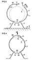
- This fitting operation can be carried out completely without any tool, and the final engagement between the hooks 13 and the hook portions 18 is accomplished by the fitter pressing the curved portion 20 radially inwards in respect of the pipe 6 and the pipe clamp 1, as indicated by means of arrow A in Fig. 4.
- the hooks 13 slide on the flanges 16, 17 essentially in the circumferential direction of the pipe clamp 1 (clockwise with regard to Fig. 4).
- the hooks 13 snap in place behind the inner hook portions 18, and a very reliable snap engagement is achieved.
- the reliable engagement is promoted especially by the end portions 10, 11 of the two pipe clamp parts 7, 8 overlapping each other in the complete engagement position (Fig. 4).
- Fig. 5 shows an intermediate position, in which the hooks 13 engage the outer hook portions 19 of the flanges 16, 17.
- the inside of the pipe clamp 1 is spaced from the outside of the pipe 6, which means that the pipe clamp 1 and the pipe 6 can be displaced relatively to each other for adjustment, for instance before the final mounting.
- the fitter applies, as described above, a force upon the curved portion 20 in the direction of arrow A, which thanks to the flange guiding between the hooks 13 and the flanges 16, 17 results in displacement of the end portion 11 in the direction of arrow B (tangentially) to the engagement position shown in Fig. 4.
- the curved portion 20 springs radially inwards and is simultaneously extended in the circumferential direction (clockwise in Fig. 5), such that the hooks 13 snap into engagement with the inner hook portions 18.
- the curved portion 20 springs back radially outwards and thus yields a tightening of the pipe clamp 1 against the pipe 6.
- the hooks 13 are pulled against the inner hook portions 18, and the inner edge or ridge 21, positioned opposite to the hooks 13, of the curved portion 20 is made to abut against the outside of the pipe 6.
- an axial groove 22 forms, which contributes to giving the pipe clamp parts 7, 8 their spring-back effect.
- the groove 22 also confers the advantage that the folded seam 23 of the downpipe 6 can be received therein.
- the engagement between the end portions 10, 11 of the pipe clamp 1 is, as mentioned above, extremely reliable, and the pipe clamp 1 usually cannot be released manually. If, for some reason, one wants to release the pipe clamp 1, use is made of a pointed object, for instance a screw driver (not shown), which is inserted in a recess 24 (Fig. 2) in the end portion 11 of the pipe clamp part 8 in connection with the hooks 13. The engagement may then be prized open.
- a pointed object for instance a screw driver (not shown)
- a recess 24 Fig. 2
- FIG. 6 shows a variant, where the pipe clamp 1 is connected to another fastening means in the form of a so-called spike 25, which has a part 26 positioned on the inside of the pipe clamp 1, more precisely in the groove 22.
- This alternative fastening means 25, 26 may constitute a separate part that is connected to the pipe clamp 1 by suitable engagement between engaging portions (not shown) of the fastening means 25, 26 and the pipe clamp 1, respectively.
- the part 26 may have projecting hooks (not shown) for engaging the edge portions of the pipe clamp 1.
- the invention is not limited to the snap-acting engagement means described above, and a number of alternative hooks and the like are included in the scope of the inventive idea as expressed in the appended claims.
- a variant is that the edges of the two end portions are designed as elongate hooks which are made to overlap each other for achieving a clamping effect.
Landscapes
- Engineering & Computer Science (AREA)
- General Engineering & Computer Science (AREA)
- Architecture (AREA)
- Civil Engineering (AREA)
- Structural Engineering (AREA)
- Mechanical Engineering (AREA)
- Clamps And Clips (AREA)
- Supports For Pipes And Cables (AREA)
- Sampling And Sample Adjustment (AREA)
- Wire Bonding (AREA)
- Mechanical Operated Clutches (AREA)
Claims (11)
- Organe de maintien de conduite de descente, comprenant un corps cylindrique (1) destiné à serrer la conduite (6) et un dispositif de fixation (2, 3 ; 25) dépassant du corps et destiné au montage de l'organe de maintien sur un mur (4) ou analogue, le corps étant élastique et ayant deux parties d'extrémité (10, 11) qui sont opposées en direction circonférentielle et pratiquement diamétralement opposées à une partie (9) du corps dont dépasse le dispositif de fixation; les deux parties d'extrémité (10, 11) du corps ayant des dispositifs (12, 13) de coopération mutuelle pourvus de crochets pour le montage et le serrage du corps autour d'une conduite, caractérisé en ce que ladite partie (9) du corps (1) dont dépasse le dispositif de fixation (2, 3 ; 25) a une gorge (22) qui s'étend parallèlement à l'axe longitudinal du corps cylindrique et se courbe vers l'extérieur du corps cylindrique, la gorge (22) donnant un effet de rétablissement élastique sur les deux parties d'extrémité (10, 11).
- Organe de maintien selon la revendication 1, dans lequel le dispositif de coopération (12, 13) a un effet d'enclenchement élastique.
- Organe de maintien selon la revendication 1 ou 2, dans lequel le dispositif de coopération d'une première partie d'extrémité (11) comporte une partie de bord qui est parallèle à l'axe longitudinal du corps cylindrique et a au moins un crochet allongé (13) destiné à coopérer avec le dispositif de coopération (12) de l' autre partie d'extrémité (10), l'autre partie d'extrémité comprenant au moins un crochet (18) de coopération par blocage avec les crochets allongés (13).
- Organe de maintien selon la revendication 3, dans lequel le dispositif de coopération (12) de l'autre partie d'extrémité (10) a des flasques ( 16, 17) de guidage des crochets allongés (13) en coopération avec les crochets (18) de la partie d'extrémité opposée (11) dans l'opération de montage.
- Organe de maintien selon la revendication 3 ou 4, dans lequel le dispositif de coopération-de l'autre partie d'extrémité (10) comprend deux languettes espacées (12) en parallèle avec l'axe longitudinal du corps cylindrique, qui ont chacune des parties de crochet (18, 19) destinées à coopérer par blocage avec les crochets allongés (13) de la partie d'extrémité opposée (11).
- Organe de maintien selon l'une quelconque des revendications précédentes, dans lequel la première partie d'extrémité (11) comprend une partie axiale courbe (20) qui est parallèle à l'axe longitudinal du corps cylindrique et élastique essentiellement en direction radiale.
- Organe de maintien selon la revendication 6, dans lequel la partie courbe (20) est courbée vers l'extérieur par rapport au corps (1).
- Organe de maintien selon la revendication 6 ou 7, dans lequel la partie courbe (20) a une arête axiale interne (21), qui est parallèle à l'axe longitudinal du corps cylindrique et placée à distance des crochets allongés (13), l'arête axiale interne étant destinée à être en butée contre la conduite (6) dans l'opération de montage.
- Organe de maintien selon l'une quelconque des revendications précédentes, dans lequel les deux parties d'extrémité (10, 11), en position de coopération, se recouvrent au moins partiellement.
- Organe de maintien selon l'une quelconque des revendications précédentes, qui est formé en une seule pièce, de préférence d'une mince feuille métallique.
- Organe de maintien selon l'une quelconque des revendications 1 à 10, dans lequel le dispositif de fixation (25) est une partie séparée destinée à être raccordée au corps (1).
Applications Claiming Priority (3)
| Application Number | Priority Date | Filing Date | Title |
|---|---|---|---|
| SE9604645 | 1996-12-18 | ||
| SE9604645A SE508849C2 (sv) | 1996-12-18 | 1996-12-18 | Hållare för stuprör |
| PCT/SE1997/002103 WO1998027293A1 (fr) | 1996-12-18 | 1997-12-16 | Support de tuyau |
Publications (2)
| Publication Number | Publication Date |
|---|---|
| EP0968340A1 EP0968340A1 (fr) | 2000-01-05 |
| EP0968340B1 true EP0968340B1 (fr) | 2004-06-09 |
Family
ID=20405013
Family Applications (1)
| Application Number | Title | Priority Date | Filing Date |
|---|---|---|---|
| EP97950554A Expired - Lifetime EP0968340B1 (fr) | 1996-12-18 | 1997-12-16 | Support de tuyau |
Country Status (9)
| Country | Link |
|---|---|
| EP (1) | EP0968340B1 (fr) |
| AU (1) | AU5352798A (fr) |
| DE (2) | DE968340T1 (fr) |
| DK (1) | DK0968340T3 (fr) |
| HU (1) | HU222063B1 (fr) |
| NO (1) | NO313249B1 (fr) |
| PL (1) | PL195982B1 (fr) |
| SE (1) | SE508849C2 (fr) |
| WO (1) | WO1998027293A1 (fr) |
Families Citing this family (5)
| Publication number | Priority date | Publication date | Assignee | Title |
|---|---|---|---|---|
| FR2820188B1 (fr) * | 2001-01-30 | 2003-05-09 | Faurecia Ind | Systeme d'accrochage d'un organe sur une piece de support, notamment pour vehicule automobile |
| ITVI20020031A1 (it) * | 2002-02-18 | 2002-05-20 | Giorgio Bassanese | Elemento antiintrusione applicabile a tubi pluviali. |
| SE0602323L (sv) * | 2006-11-03 | 2008-02-26 | Plannja Siba Ab | Stuprörssvep |
| SE0602324L (sv) * | 2006-11-03 | 2008-02-26 | Plannja Siba Ab | Stuprörssvep och sätt att montera sådant |
| GB2574671A (en) * | 2018-06-15 | 2019-12-18 | D Line Europe Ltd | Conduit clip |
Family Cites Families (5)
| Publication number | Priority date | Publication date | Assignee | Title |
|---|---|---|---|---|
| CH643338A5 (en) * | 1979-10-15 | 1984-05-30 | Egli Fischer & Co | Pipe clamp |
| EP0135698B1 (fr) * | 1983-07-21 | 1988-12-28 | Egon Striedelmeyer | Patte de fixation de tuyau |
| IT213235Z2 (it) * | 1987-01-30 | 1989-11-13 | Cattani & C Spa Off | Staffa di sostegno in particolareper tubi |
| ES2028415T3 (es) * | 1988-07-18 | 1992-07-01 | Egli, Fischer & Co. Ag | Abrazadera tubular. |
| US5478033A (en) * | 1994-04-19 | 1995-12-26 | Hungerford, Jr.; Charles S. | Pipe clamp |
-
1996
- 1996-12-18 SE SE9604645A patent/SE508849C2/sv unknown
-
1997
- 1997-12-16 DE DE0968340T patent/DE968340T1/de active Pending
- 1997-12-16 EP EP97950554A patent/EP0968340B1/fr not_active Expired - Lifetime
- 1997-12-16 AU AU53527/98A patent/AU5352798A/en not_active Abandoned
- 1997-12-16 DE DE69729486T patent/DE69729486T2/de not_active Expired - Lifetime
- 1997-12-16 PL PL97334016A patent/PL195982B1/pl not_active IP Right Cessation
- 1997-12-16 WO PCT/SE1997/002103 patent/WO1998027293A1/fr not_active Ceased
- 1997-12-16 DK DK97950554T patent/DK0968340T3/da active
- 1997-12-16 HU HU0000394A patent/HU222063B1/hu not_active IP Right Cessation
-
1999
- 1999-06-04 NO NO19992722A patent/NO313249B1/no not_active IP Right Cessation
Also Published As
| Publication number | Publication date |
|---|---|
| DE968340T1 (de) | 2002-01-17 |
| EP0968340A1 (fr) | 2000-01-05 |
| AU5352798A (en) | 1998-07-15 |
| DK0968340T3 (da) | 2004-07-19 |
| PL195982B1 (pl) | 2007-11-30 |
| NO313249B1 (no) | 2002-09-02 |
| PL334016A1 (en) | 2000-01-31 |
| HUP0000394A2 (hu) | 2000-08-28 |
| HU222063B1 (hu) | 2003-04-28 |
| DE69729486D1 (de) | 2004-07-15 |
| HUP0000394A3 (en) | 2000-09-28 |
| NO992722L (no) | 1999-06-04 |
| SE9604645D0 (sv) | 1996-12-18 |
| SE508849C2 (sv) | 1998-11-09 |
| WO1998027293A1 (fr) | 1998-06-25 |
| DE69729486T2 (de) | 2005-07-07 |
| NO992722D0 (no) | 1999-06-04 |
| SE9604645L (sv) | 1998-06-19 |
Similar Documents
| Publication | Publication Date | Title |
|---|---|---|
| US4550451A (en) | Universal plumbing pipe locator and support | |
| US8141831B2 (en) | Hanger connector for flexible tubing | |
| SK145199A3 (en) | Pipe clamp | |
| US6088886A (en) | Hose clamp having a spring ring disposed within the clamp | |
| US4742600A (en) | Band clamp | |
| US5813705A (en) | Snap-action pipe coupling retainer | |
| US8047476B2 (en) | Pipe clip having a curved flange | |
| CN101460775B (zh) | 夹紧圈 | |
| CA1307305C (fr) | Raccord moule pour canalisation de fluide, avec ecrou orientable integre | |
| US6158066A (en) | Anti-rotation pipe locator and holder | |
| JPH09100979A (ja) | ホース締め付け保持装置 | |
| EP3680532B1 (fr) | Pince de tuyau en plastique | |
| US20030090105A1 (en) | Connecting fitting with an elastic ring as a stop | |
| JP2003097517A (ja) | 管締め付け具、特に管継手 | |
| US4306740A (en) | Hose clamp structure and hose construction employing same | |
| US10584817B2 (en) | Hose clamp with retaining bracket | |
| US11384866B2 (en) | Pipe clamp | |
| EP0968340B1 (fr) | Support de tuyau | |
| AU696176B2 (en) | Pipe and cable clamp with base part and receiving strap | |
| EP2682656B1 (fr) | Collier de serrage de tuyau doté d'une rondelle élastique | |
| US5048776A (en) | Pipe clamp | |
| US5940939A (en) | One-piece flat band clamp | |
| EP0344862B1 (fr) | Attache pour tuyau | |
| CA1260514A (fr) | Dispositif pour brancher l'extremite d'un tuyau souple sur un manchon de raccordement | |
| JP4296882B2 (ja) | ホースクランプ |
Legal Events
| Date | Code | Title | Description |
|---|---|---|---|
| PUAI | Public reference made under article 153(3) epc to a published international application that has entered the european phase |
Free format text: ORIGINAL CODE: 0009012 |
|
| 17P | Request for examination filed |
Effective date: 19990610 |
|
| AK | Designated contracting states |
Kind code of ref document: A1 Designated state(s): DE DK FI FR GB SE |
|
| EL | Fr: translation of claims filed | ||
| DET | De: translation of patent claims | ||
| 17Q | First examination report despatched |
Effective date: 20030404 |
|
| GRAP | Despatch of communication of intention to grant a patent |
Free format text: ORIGINAL CODE: EPIDOSNIGR1 |
|
| GRAS | Grant fee paid |
Free format text: ORIGINAL CODE: EPIDOSNIGR3 |
|
| GRAA | (expected) grant |
Free format text: ORIGINAL CODE: 0009210 |
|
| AK | Designated contracting states |
Kind code of ref document: B1 Designated state(s): DE DK FI FR GB SE |
|
| PG25 | Lapsed in a contracting state [announced via postgrant information from national office to epo] |
Ref country code: FR Free format text: LAPSE BECAUSE OF FAILURE TO SUBMIT A TRANSLATION OF THE DESCRIPTION OR TO PAY THE FEE WITHIN THE PRESCRIBED TIME-LIMIT Effective date: 20040609 Ref country code: FI Free format text: LAPSE BECAUSE OF FAILURE TO SUBMIT A TRANSLATION OF THE DESCRIPTION OR TO PAY THE FEE WITHIN THE PRESCRIBED TIME-LIMIT Effective date: 20040609 |
|
| REG | Reference to a national code |
Ref country code: GB Ref legal event code: FG4D |
|
| REF | Corresponds to: |
Ref document number: 69729486 Country of ref document: DE Date of ref document: 20040715 Kind code of ref document: P |
|
| REG | Reference to a national code |
Ref country code: DK Ref legal event code: T3 |
|
| PG25 | Lapsed in a contracting state [announced via postgrant information from national office to epo] |
Ref country code: SE Free format text: LAPSE BECAUSE OF FAILURE TO SUBMIT A TRANSLATION OF THE DESCRIPTION OR TO PAY THE FEE WITHIN THE PRESCRIBED TIME-LIMIT Effective date: 20040909 |
|
| PLBE | No opposition filed within time limit |
Free format text: ORIGINAL CODE: 0009261 |
|
| STAA | Information on the status of an ep patent application or granted ep patent |
Free format text: STATUS: NO OPPOSITION FILED WITHIN TIME LIMIT |
|
| 26N | No opposition filed |
Effective date: 20050310 |
|
| EN | Fr: translation not filed | ||
| PGFP | Annual fee paid to national office [announced via postgrant information from national office to epo] |
Ref country code: DK Payment date: 20101210 Year of fee payment: 14 |
|
| PGFP | Annual fee paid to national office [announced via postgrant information from national office to epo] |
Ref country code: GB Payment date: 20101221 Year of fee payment: 14 |
|
| PGFP | Annual fee paid to national office [announced via postgrant information from national office to epo] |
Ref country code: DE Payment date: 20101222 Year of fee payment: 14 |
|
| REG | Reference to a national code |
Ref country code: DK Ref legal event code: EBP |
|
| GBPC | Gb: european patent ceased through non-payment of renewal fee |
Effective date: 20121216 |
|
| REG | Reference to a national code |
Ref country code: DE Ref legal event code: R119 Ref document number: 69729486 Country of ref document: DE Effective date: 20130702 |
|
| PG25 | Lapsed in a contracting state [announced via postgrant information from national office to epo] |
Ref country code: DE Free format text: LAPSE BECAUSE OF NON-PAYMENT OF DUE FEES Effective date: 20130702 |
|
| PG25 | Lapsed in a contracting state [announced via postgrant information from national office to epo] |
Ref country code: GB Free format text: LAPSE BECAUSE OF NON-PAYMENT OF DUE FEES Effective date: 20121216 |
|
| PG25 | Lapsed in a contracting state [announced via postgrant information from national office to epo] |
Ref country code: DK Free format text: LAPSE BECAUSE OF NON-PAYMENT OF DUE FEES Effective date: 20130102 |