EP0968050B1 - Multiautoklave für kombinierte synthese von zeolithen und anderen stoffen - Google Patents
Multiautoklave für kombinierte synthese von zeolithen und anderen stoffen Download PDFInfo
- Publication number
- EP0968050B1 EP0968050B1 EP98904447A EP98904447A EP0968050B1 EP 0968050 B1 EP0968050 B1 EP 0968050B1 EP 98904447 A EP98904447 A EP 98904447A EP 98904447 A EP98904447 A EP 98904447A EP 0968050 B1 EP0968050 B1 EP 0968050B1
- Authority
- EP
- European Patent Office
- Prior art keywords
- multiautoclave
- perforations
- reactor vessel
- central block
- vessel according
- Prior art date
- Legal status (The legal status is an assumption and is not a legal conclusion. Google has not performed a legal analysis and makes no representation as to the accuracy of the status listed.)
- Expired - Lifetime
Links
- 239000000463 material Substances 0.000 title claims abstract description 14
- 238000003786 synthesis reaction Methods 0.000 title abstract description 67
- 230000015572 biosynthetic process Effects 0.000 title abstract description 51
- 239000010457 zeolite Substances 0.000 title abstract description 28
- 238000007789 sealing Methods 0.000 claims description 22
- 238000006243 chemical reaction Methods 0.000 claims description 16
- 229920006254 polymer film Polymers 0.000 claims description 7
- 239000012528 membrane Substances 0.000 claims 3
- 239000000203 mixture Substances 0.000 abstract description 25
- 238000013461 design Methods 0.000 abstract description 17
- 238000000034 method Methods 0.000 abstract description 14
- 230000007246 mechanism Effects 0.000 abstract description 7
- 229910052751 metal Inorganic materials 0.000 abstract description 4
- 239000002184 metal Substances 0.000 abstract description 4
- YNAVUWVOSKDBBP-UHFFFAOYSA-N Morpholine Chemical compound C1COCCN1 YNAVUWVOSKDBBP-UHFFFAOYSA-N 0.000 description 22
- 239000004809 Teflon Substances 0.000 description 21
- 229920006362 Teflon® Polymers 0.000 description 21
- 239000000243 solution Substances 0.000 description 17
- VYPSYNLAJGMNEJ-UHFFFAOYSA-N Silicium dioxide Chemical compound O=[Si]=O VYPSYNLAJGMNEJ-UHFFFAOYSA-N 0.000 description 15
- HEMHJVSKTPXQMS-UHFFFAOYSA-M Sodium hydroxide Chemical compound [OH-].[Na+] HEMHJVSKTPXQMS-UHFFFAOYSA-M 0.000 description 15
- XLYOFNOQVPJJNP-UHFFFAOYSA-N water Chemical compound O XLYOFNOQVPJJNP-UHFFFAOYSA-N 0.000 description 15
- 229910021536 Zeolite Inorganic materials 0.000 description 14
- HNPSIPDUKPIQMN-UHFFFAOYSA-N dioxosilane;oxo(oxoalumanyloxy)alumane Chemical compound O=[Si]=O.O=[Al]O[Al]=O HNPSIPDUKPIQMN-UHFFFAOYSA-N 0.000 description 14
- 239000007788 liquid Substances 0.000 description 13
- 239000000376 reactant Substances 0.000 description 9
- 239000000499 gel Substances 0.000 description 8
- 229910000831 Steel Inorganic materials 0.000 description 7
- 239000013078 crystal Substances 0.000 description 7
- 239000010959 steel Substances 0.000 description 7
- KKCBUQHMOMHUOY-UHFFFAOYSA-N Na2O Inorganic materials [O-2].[Na+].[Na+] KKCBUQHMOMHUOY-UHFFFAOYSA-N 0.000 description 6
- PNEYBMLMFCGWSK-UHFFFAOYSA-N aluminium oxide Inorganic materials [O-2].[O-2].[O-2].[Al+3].[Al+3] PNEYBMLMFCGWSK-UHFFFAOYSA-N 0.000 description 5
- 239000003153 chemical reaction reagent Substances 0.000 description 5
- 229910052681 coesite Inorganic materials 0.000 description 5
- 229910052593 corundum Inorganic materials 0.000 description 5
- 229910052906 cristobalite Inorganic materials 0.000 description 5
- 239000011521 glass Substances 0.000 description 5
- 238000002360 preparation method Methods 0.000 description 5
- 239000011541 reaction mixture Substances 0.000 description 5
- 239000000377 silicon dioxide Substances 0.000 description 5
- 229910052682 stishovite Inorganic materials 0.000 description 5
- 239000000758 substrate Substances 0.000 description 5
- 229910052905 tridymite Inorganic materials 0.000 description 5
- 229910001845 yogo sapphire Inorganic materials 0.000 description 5
- 238000002441 X-ray diffraction Methods 0.000 description 4
- 239000004411 aluminium Substances 0.000 description 4
- 229910052782 aluminium Inorganic materials 0.000 description 4
- XAGFODPZIPBFFR-UHFFFAOYSA-N aluminium Chemical compound [Al] XAGFODPZIPBFFR-UHFFFAOYSA-N 0.000 description 4
- 238000010438 heat treatment Methods 0.000 description 4
- 239000012071 phase Substances 0.000 description 4
- 229920000642 polymer Polymers 0.000 description 4
- 230000033458 reproduction Effects 0.000 description 4
- 235000012239 silicon dioxide Nutrition 0.000 description 4
- 239000007787 solid Substances 0.000 description 4
- 238000005406 washing Methods 0.000 description 4
- ZMANZCXQSJIPKH-UHFFFAOYSA-N Triethylamine Chemical compound CCN(CC)CC ZMANZCXQSJIPKH-UHFFFAOYSA-N 0.000 description 3
- 229920001222 biopolymer Polymers 0.000 description 3
- 238000009472 formulation Methods 0.000 description 3
- 239000011159 matrix material Substances 0.000 description 3
- 238000002156 mixing Methods 0.000 description 3
- -1 polypropylene Polymers 0.000 description 3
- 108090000623 proteins and genes Proteins 0.000 description 3
- 102000004169 proteins and genes Human genes 0.000 description 3
- 238000011084 recovery Methods 0.000 description 3
- 229910001220 stainless steel Inorganic materials 0.000 description 3
- 239000010935 stainless steel Substances 0.000 description 3
- 239000004696 Poly ether ether ketone Substances 0.000 description 2
- 239000004743 Polypropylene Substances 0.000 description 2
- 238000004458 analytical method Methods 0.000 description 2
- JUPQTSLXMOCDHR-UHFFFAOYSA-N benzene-1,4-diol;bis(4-fluorophenyl)methanone Chemical compound OC1=CC=C(O)C=C1.C1=CC(F)=CC=C1C(=O)C1=CC=C(F)C=C1 JUPQTSLXMOCDHR-UHFFFAOYSA-N 0.000 description 2
- 238000002425 crystallisation Methods 0.000 description 2
- 230000008025 crystallization Effects 0.000 description 2
- PAFZNILMFXTMIY-UHFFFAOYSA-N cyclohexylamine Chemical group NC1CCCCC1 PAFZNILMFXTMIY-UHFFFAOYSA-N 0.000 description 2
- 238000009826 distribution Methods 0.000 description 2
- 238000001035 drying Methods 0.000 description 2
- 230000000694 effects Effects 0.000 description 2
- 229920001971 elastomer Polymers 0.000 description 2
- 239000000806 elastomer Substances 0.000 description 2
- 238000005516 engineering process Methods 0.000 description 2
- 238000001027 hydrothermal synthesis Methods 0.000 description 2
- 239000002808 molecular sieve Substances 0.000 description 2
- 150000002894 organic compounds Chemical class 0.000 description 2
- 229920002530 polyetherether ketone Polymers 0.000 description 2
- 229920001155 polypropylene Polymers 0.000 description 2
- 238000011160 research Methods 0.000 description 2
- 238000012216 screening Methods 0.000 description 2
- 239000011734 sodium Substances 0.000 description 2
- 229910001388 sodium aluminate Inorganic materials 0.000 description 2
- URGAHOPLAPQHLN-UHFFFAOYSA-N sodium aluminosilicate Chemical compound [Na+].[Al+3].[O-][Si]([O-])=O.[O-][Si]([O-])=O URGAHOPLAPQHLN-UHFFFAOYSA-N 0.000 description 2
- 239000002904 solvent Substances 0.000 description 2
- 238000012360 testing method Methods 0.000 description 2
- 229910000619 316 stainless steel Inorganic materials 0.000 description 1
- 229910017119 AlPO Inorganic materials 0.000 description 1
- 241000269350 Anura Species 0.000 description 1
- OKTJSMMVPCPJKN-UHFFFAOYSA-N Carbon Chemical compound [C] OKTJSMMVPCPJKN-UHFFFAOYSA-N 0.000 description 1
- 229920002449 FKM Polymers 0.000 description 1
- KRHYYFGTRYWZRS-UHFFFAOYSA-M Fluoride anion Chemical compound [F-] KRHYYFGTRYWZRS-UHFFFAOYSA-M 0.000 description 1
- 239000004677 Nylon Substances 0.000 description 1
- 239000004698 Polyethylene Substances 0.000 description 1
- RTAQQCXQSZGOHL-UHFFFAOYSA-N Titanium Chemical compound [Ti] RTAQQCXQSZGOHL-UHFFFAOYSA-N 0.000 description 1
- 239000002250 absorbent Substances 0.000 description 1
- 230000002745 absorbent Effects 0.000 description 1
- 239000011358 absorbing material Substances 0.000 description 1
- 239000002253 acid Substances 0.000 description 1
- 239000012670 alkaline solution Substances 0.000 description 1
- ILRRQNADMUWWFW-UHFFFAOYSA-K aluminium phosphate Chemical compound O1[Al]2OP1(=O)O2 ILRRQNADMUWWFW-UHFFFAOYSA-K 0.000 description 1
- 229940009859 aluminum phosphate Drugs 0.000 description 1
- ANBBXQWFNXMHLD-UHFFFAOYSA-N aluminum;sodium;oxygen(2-) Chemical compound [O-2].[O-2].[Na+].[Al+3] ANBBXQWFNXMHLD-UHFFFAOYSA-N 0.000 description 1
- 238000009835 boiling Methods 0.000 description 1
- 238000001354 calcination Methods 0.000 description 1
- 229910052799 carbon Inorganic materials 0.000 description 1
- 239000003575 carbonaceous material Substances 0.000 description 1
- 231100000481 chemical toxicant Toxicity 0.000 description 1
- 238000004140 cleaning Methods 0.000 description 1
- 239000008119 colloidal silica Substances 0.000 description 1
- 150000001875 compounds Chemical class 0.000 description 1
- 238000009792 diffusion process Methods 0.000 description 1
- 230000029087 digestion Effects 0.000 description 1
- WEHWNAOGRSTTBQ-UHFFFAOYSA-N dipropylamine Chemical compound CCCNCCC WEHWNAOGRSTTBQ-UHFFFAOYSA-N 0.000 description 1
- 238000004090 dissolution Methods 0.000 description 1
- 239000012153 distilled water Substances 0.000 description 1
- 238000002474 experimental method Methods 0.000 description 1
- 238000001914 filtration Methods 0.000 description 1
- 238000011010 flushing procedure Methods 0.000 description 1
- 239000000446 fuel Substances 0.000 description 1
- 238000000265 homogenisation Methods 0.000 description 1
- 238000010335 hydrothermal treatment Methods 0.000 description 1
- 238000007654 immersion Methods 0.000 description 1
- 238000009413 insulation Methods 0.000 description 1
- 239000007791 liquid phase Substances 0.000 description 1
- 229920002521 macromolecule Polymers 0.000 description 1
- 238000012423 maintenance Methods 0.000 description 1
- 238000004519 manufacturing process Methods 0.000 description 1
- 238000005259 measurement Methods 0.000 description 1
- 239000000155 melt Substances 0.000 description 1
- 239000012229 microporous material Substances 0.000 description 1
- 229920001778 nylon Polymers 0.000 description 1
- 239000003973 paint Substances 0.000 description 1
- 239000004033 plastic Substances 0.000 description 1
- 229920003023 plastic Polymers 0.000 description 1
- 229920000573 polyethylene Polymers 0.000 description 1
- 239000002861 polymer material Substances 0.000 description 1
- 238000003825 pressing Methods 0.000 description 1
- 108090000765 processed proteins & peptides Proteins 0.000 description 1
- 239000010453 quartz Substances 0.000 description 1
- 230000035484 reaction time Effects 0.000 description 1
- 238000012827 research and development Methods 0.000 description 1
- 238000013341 scale-up Methods 0.000 description 1
- RMAQACBXLXPBSY-UHFFFAOYSA-N silicic acid Chemical compound O[Si](O)(O)O RMAQACBXLXPBSY-UHFFFAOYSA-N 0.000 description 1
- 239000011343 solid material Substances 0.000 description 1
- 238000003756 stirring Methods 0.000 description 1
- 239000000126 substance Substances 0.000 description 1
- 230000009897 systematic effect Effects 0.000 description 1
- 229940073455 tetraethylammonium hydroxide Drugs 0.000 description 1
- LRGJRHZIDJQFCL-UHFFFAOYSA-M tetraethylazanium;hydroxide Chemical compound [OH-].CC[N+](CC)(CC)CC LRGJRHZIDJQFCL-UHFFFAOYSA-M 0.000 description 1
- 239000010936 titanium Substances 0.000 description 1
- 229910052719 titanium Inorganic materials 0.000 description 1
- 239000003440 toxic substance Substances 0.000 description 1
- YFTHZRPMJXBUME-UHFFFAOYSA-N tripropylamine Chemical compound CCCN(CCC)CCC YFTHZRPMJXBUME-UHFFFAOYSA-N 0.000 description 1
Images

Classifications
-
- B—PERFORMING OPERATIONS; TRANSPORTING
- B01—PHYSICAL OR CHEMICAL PROCESSES OR APPARATUS IN GENERAL
- B01J—CHEMICAL OR PHYSICAL PROCESSES, e.g. CATALYSIS OR COLLOID CHEMISTRY; THEIR RELEVANT APPARATUS
- B01J3/00—Processes of utilising sub-atmospheric or super-atmospheric pressure to effect chemical or physical change of matter; Apparatus therefor
- B01J3/04—Pressure vessels, e.g. autoclaves
-
- B—PERFORMING OPERATIONS; TRANSPORTING
- B01—PHYSICAL OR CHEMICAL PROCESSES OR APPARATUS IN GENERAL
- B01J—CHEMICAL OR PHYSICAL PROCESSES, e.g. CATALYSIS OR COLLOID CHEMISTRY; THEIR RELEVANT APPARATUS
- B01J19/00—Chemical, physical or physico-chemical processes in general; Their relevant apparatus
- B01J19/0046—Sequential or parallel reactions, e.g. for the synthesis of polypeptides or polynucleotides; Apparatus and devices for combinatorial chemistry or for making molecular arrays
-
- C—CHEMISTRY; METALLURGY
- C01—INORGANIC CHEMISTRY
- C01B—NON-METALLIC ELEMENTS; COMPOUNDS THEREOF; METALLOIDS OR COMPOUNDS THEREOF NOT COVERED BY SUBCLASS C01C
- C01B39/00—Compounds having molecular sieve and base-exchange properties, e.g. crystalline zeolites; Their preparation; After-treatment, e.g. ion-exchange or dealumination
- C01B39/02—Crystalline aluminosilicate zeolites; Isomorphous compounds thereof; Direct preparation thereof; Preparation thereof starting from a reaction mixture containing a crystalline zeolite of another type, or from preformed reactants; After-treatment thereof
-
- B—PERFORMING OPERATIONS; TRANSPORTING
- B01—PHYSICAL OR CHEMICAL PROCESSES OR APPARATUS IN GENERAL
- B01J—CHEMICAL OR PHYSICAL PROCESSES, e.g. CATALYSIS OR COLLOID CHEMISTRY; THEIR RELEVANT APPARATUS
- B01J2219/00—Chemical, physical or physico-chemical processes in general; Their relevant apparatus
- B01J2219/00274—Sequential or parallel reactions; Apparatus and devices for combinatorial chemistry or for making arrays; Chemical library technology
- B01J2219/00277—Apparatus
- B01J2219/00279—Features relating to reactor vessels
- B01J2219/00306—Reactor vessels in a multiple arrangement
- B01J2219/00313—Reactor vessels in a multiple arrangement the reactor vessels being formed by arrays of wells in blocks
- B01J2219/00319—Reactor vessels in a multiple arrangement the reactor vessels being formed by arrays of wells in blocks the blocks being mounted in stacked arrangements
-
- B—PERFORMING OPERATIONS; TRANSPORTING
- B01—PHYSICAL OR CHEMICAL PROCESSES OR APPARATUS IN GENERAL
- B01J—CHEMICAL OR PHYSICAL PROCESSES, e.g. CATALYSIS OR COLLOID CHEMISTRY; THEIR RELEVANT APPARATUS
- B01J2219/00—Chemical, physical or physico-chemical processes in general; Their relevant apparatus
- B01J2219/00274—Sequential or parallel reactions; Apparatus and devices for combinatorial chemistry or for making arrays; Chemical library technology
- B01J2219/00277—Apparatus
- B01J2219/00279—Features relating to reactor vessels
- B01J2219/00331—Details of the reactor vessels
- B01J2219/00333—Closures attached to the reactor vessels
- B01J2219/00335—Septa
-
- B—PERFORMING OPERATIONS; TRANSPORTING
- B01—PHYSICAL OR CHEMICAL PROCESSES OR APPARATUS IN GENERAL
- B01J—CHEMICAL OR PHYSICAL PROCESSES, e.g. CATALYSIS OR COLLOID CHEMISTRY; THEIR RELEVANT APPARATUS
- B01J2219/00—Chemical, physical or physico-chemical processes in general; Their relevant apparatus
- B01J2219/00274—Sequential or parallel reactions; Apparatus and devices for combinatorial chemistry or for making arrays; Chemical library technology
- B01J2219/00277—Apparatus
- B01J2219/00279—Features relating to reactor vessels
- B01J2219/00331—Details of the reactor vessels
- B01J2219/00333—Closures attached to the reactor vessels
- B01J2219/00349—Spheres
-
- B—PERFORMING OPERATIONS; TRANSPORTING
- B01—PHYSICAL OR CHEMICAL PROCESSES OR APPARATUS IN GENERAL
- B01J—CHEMICAL OR PHYSICAL PROCESSES, e.g. CATALYSIS OR COLLOID CHEMISTRY; THEIR RELEVANT APPARATUS
- B01J2219/00—Chemical, physical or physico-chemical processes in general; Their relevant apparatus
- B01J2219/00274—Sequential or parallel reactions; Apparatus and devices for combinatorial chemistry or for making arrays; Chemical library technology
- B01J2219/00277—Apparatus
- B01J2219/00477—Means for pressurising the reaction vessels
-
- B—PERFORMING OPERATIONS; TRANSPORTING
- B01—PHYSICAL OR CHEMICAL PROCESSES OR APPARATUS IN GENERAL
- B01J—CHEMICAL OR PHYSICAL PROCESSES, e.g. CATALYSIS OR COLLOID CHEMISTRY; THEIR RELEVANT APPARATUS
- B01J2219/00—Chemical, physical or physico-chemical processes in general; Their relevant apparatus
- B01J2219/00274—Sequential or parallel reactions; Apparatus and devices for combinatorial chemistry or for making arrays; Chemical library technology
- B01J2219/00583—Features relative to the processes being carried out
- B01J2219/00585—Parallel processes
-
- B—PERFORMING OPERATIONS; TRANSPORTING
- B01—PHYSICAL OR CHEMICAL PROCESSES OR APPARATUS IN GENERAL
- B01J—CHEMICAL OR PHYSICAL PROCESSES, e.g. CATALYSIS OR COLLOID CHEMISTRY; THEIR RELEVANT APPARATUS
- B01J2219/00—Chemical, physical or physico-chemical processes in general; Their relevant apparatus
- B01J2219/00274—Sequential or parallel reactions; Apparatus and devices for combinatorial chemistry or for making arrays; Chemical library technology
- B01J2219/00583—Features relative to the processes being carried out
- B01J2219/00596—Solid-phase processes
-
- B—PERFORMING OPERATIONS; TRANSPORTING
- B01—PHYSICAL OR CHEMICAL PROCESSES OR APPARATUS IN GENERAL
- B01J—CHEMICAL OR PHYSICAL PROCESSES, e.g. CATALYSIS OR COLLOID CHEMISTRY; THEIR RELEVANT APPARATUS
- B01J2219/00—Chemical, physical or physico-chemical processes in general; Their relevant apparatus
- B01J2219/00274—Sequential or parallel reactions; Apparatus and devices for combinatorial chemistry or for making arrays; Chemical library technology
- B01J2219/00583—Features relative to the processes being carried out
- B01J2219/00601—High-pressure processes
-
- B—PERFORMING OPERATIONS; TRANSPORTING
- B01—PHYSICAL OR CHEMICAL PROCESSES OR APPARATUS IN GENERAL
- B01J—CHEMICAL OR PHYSICAL PROCESSES, e.g. CATALYSIS OR COLLOID CHEMISTRY; THEIR RELEVANT APPARATUS
- B01J2219/00—Chemical, physical or physico-chemical processes in general; Their relevant apparatus
- B01J2219/00274—Sequential or parallel reactions; Apparatus and devices for combinatorial chemistry or for making arrays; Chemical library technology
- B01J2219/00718—Type of compounds synthesised
- B01J2219/00745—Inorganic compounds
- B01J2219/00747—Catalysts
-
- B—PERFORMING OPERATIONS; TRANSPORTING
- B01—PHYSICAL OR CHEMICAL PROCESSES OR APPARATUS IN GENERAL
- B01J—CHEMICAL OR PHYSICAL PROCESSES, e.g. CATALYSIS OR COLLOID CHEMISTRY; THEIR RELEVANT APPARATUS
- B01J2219/00—Chemical, physical or physico-chemical processes in general; Their relevant apparatus
- B01J2219/00274—Sequential or parallel reactions; Apparatus and devices for combinatorial chemistry or for making arrays; Chemical library technology
- B01J2219/00718—Type of compounds synthesised
- B01J2219/00745—Inorganic compounds
- B01J2219/0075—Metal based compounds
- B01J2219/00754—Metal oxides
-
- C—CHEMISTRY; METALLURGY
- C40—COMBINATORIAL TECHNOLOGY
- C40B—COMBINATORIAL CHEMISTRY; LIBRARIES, e.g. CHEMICAL LIBRARIES
- C40B30/00—Methods of screening libraries
- C40B30/08—Methods of screening libraries by measuring catalytic activity
-
- C—CHEMISTRY; METALLURGY
- C40—COMBINATORIAL TECHNOLOGY
- C40B—COMBINATORIAL CHEMISTRY; LIBRARIES, e.g. CHEMICAL LIBRARIES
- C40B40/00—Libraries per se, e.g. arrays, mixtures
- C40B40/18—Libraries containing only inorganic compounds or inorganic materials
-
- C—CHEMISTRY; METALLURGY
- C40—COMBINATORIAL TECHNOLOGY
- C40B—COMBINATORIAL CHEMISTRY; LIBRARIES, e.g. CHEMICAL LIBRARIES
- C40B60/00—Apparatus specially adapted for use in combinatorial chemistry or with libraries
- C40B60/14—Apparatus specially adapted for use in combinatorial chemistry or with libraries for creating libraries
Definitions
- the present invention relates to a pressure and temperature reactor vessel, especially a multiautoclave and to details concerning the design of this equipment.
- zeolites are prepared by so-called hydrothermal synthesis at temperatures ranging from 100°C to 200°C requiring crystallization times of 1 hour or more.
- hydrothermal synthesis at temperatures ranging from 100°C to 200°C requiring crystallization times of 1 hour or more.
- pressure vessels For syntheses being carried out at temperatures that are higher than the solvent's boiling point, it is necessary to use pressure vessels, and these have to be suitable for the temperature and pressure used during the operation.
- the pressure vessel has to be designed so that the handling of it does not represent any unnecessary hazard, provided it is used according to working instructions.
- Zeolite syntheses are usually performed in strongly alkaline media, often at pH>14, and the reaction mixture will often contain toxic chemicals, such as e.g. fluoride.
- Zeolite synthesis is often carried out by keeping the synthesis mixture at around 100°C for at least 6 h. At these moderate temperatures sealed chambers are necessary in order to avoid drying out of the synthesis mixture.
- Zeolite Y can be prepared according to US 3.130.007, Example 1, by dissolving 5 g sodium aluminate containing 30 weight percent Na 2 O and 44 weight percent Al 2 O 3 and 22 g sodium hydroxide containing 77.5 weight percent Na 2 O in 89,5 ml distilled water. This solution was added to 124.2 g of an aqueous colloidal silica sol with 29.5 weight percent SiO 2 , so that the resulting mixture had a composition corresponding to 13.9 Na 2 O : Al 2 O 3 : 28.2 SiO 2 : 471 H 2 O, and the mixture was homogenized by stirring.
- each reaction mixture is typically prepared in batches of 5 to 100 g and crystallized in expensive and heavy autoclaves with internal volumes often in the range of 25 to 250 ml and with weights of up to 8 kg per autoclave, causing considerable expense due to a large consumption of often expensive reagents and due to the fact that the handling of the heavy autoclaves often makes it impossible to handle more than one autoclave at the time, and finally that the size of the autoclaves limits the number of autoclaves that may be placed in each oven or heating unit.
- the combination of all these elements are, according to known technology, making each zeolite synthesis a very resource intensive process, and there is a great need for greater efficiency, rationalization, downscaling and automation.
- WO 95/12608-Al discloses an apparatus and a method for a) synthesis of several molecules on substrates, comprising distribution of the substrates in the reaction chambers, b) combination of the first addition of these molecules with different reagents in each of the reaction chambers, c) moving the substrates through tubing to separate mixing chambers where the substrates are mixed, d) redistribution of the substrates by transport through tubing back to the reaction chambers, and e) combination of a second portion of different composition to the first portions of molecules in the different reaction chambers in order to prepare new mixtures.
- One objective of the present invention has been to develop a complete system for screening of synthesis conditions for preparation of zeolites and other non-carbon materials requiring hydrothermal conditions in the temperature range 100°C to 250°C in a more cost efficient manner, and it has thus been of interest to improve a series of parameters, which means making them more cost efficient Some of these parameters are:
- Another objective of the present invention described here has been to design automated equipment for larger synthesis series and prepare formulations based on mixtures of different liquids/solutions with varying reactant ratios.
- the present invention represents a break-through in terms of cost reduction for e.g zeolite synthesis in that the reaction mixture crystallizes in a volume reduced typically 1/100 of what has been used conventionally, thereby achieving reduced consumption of reactants and cheaper syntheses, and further by enabling automated addition of reactants, e.g. by having 100 or more available reaction chambers in one single multiautoclave, and that the multiautoclave plates can be connected to a pipetting machine that makes quick and exact addition of all liquid reactants possible, and by being able to place several such plates with reaction chambers on top of each other without difficulty.
- an important feature of the present invention is the simple and not very time consuming operation of the multiautoclave.
- the present invention relates to a multiautoclave reactor vessel for use at elevated pressures comprising:
- Applications for the present invention may, in addition to zeolite synthesis, be in any field of activities within research and development connected to products where at least one production-step comprises the mixing of different liquids, e.g. in the fields of organic and inorganic syntheses, paint production, formulation of fuels, food industry, etc., and, furthermore, applications within clinical testing, dissolution and digestion of samples with acid etc. where a liquid reactant is added to a liquid or solid.
- the invention is in particular aimed at applications where open vessels cannot be used, and more specifically for applications where it is required to operate at temperatures which will cause elevated pressures in the liquid part of the mixture.
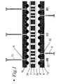
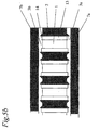
- Figure 1 presents a side-view of the multiautoclave with the single components disassembled
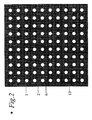
- Figure 2 shows a top-view of the multiautoclave
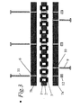
- Figure 3 shows an alternative design of the multiautoclave (side-view).
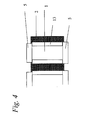
- Figure 4 shows a section of one of the chambers of the multiautoclave (side view) equipped with a Teflon liner and disc-shaped lids.
- Figure 5a shows a section of a multiautoclave embodiment in "exploded" view, and in Figure 5b in closed mode.
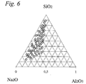
- Figure 6 presents an example of different chemical compositions covered in one single experiment using the multiautoclave.
- the invention comprises a unit containing a multitude of pressure vessels, also referred to as a multiautoclave.
- This multiautoclave has typically from 10 to 10.000 or more small, separate chambers (1), each typically with a volume of 0.001 - 10 ml.
- the multiautoclave is composed of a set of plates (2, 7a, 7b) and optionally thin laminae (3a, 3b) which are stacked so that they form a matrix of small chambers (1), as shown in Figures 1 - 5.
- the thickness of the different plates and laminae may vary, always keeping in mind that a maximum number of small chambers with optimal size is desired, and that the chambers must be leak tight and dimensioned such that no excessive degree of deformation will take place under the operational conditions which the equipment is designed for.
- the central block consisting in a perforated plate (2), with a multitude of perforations, serve - when sandwiched between the plates (7a and 7b) and closed ⁇ as the frame of the pressure chambers, and may for use at higher temperatures (150 - 250°C) be made from stainless steel, aluminium, titanium or other rigid material s.a. PEEK or the like, with perforations of e.g.
- each perforation is lined with a segment of Teflon tubing or tubing made from another suitable polymer material, and where the walls of the linings e.g. can have a thickness of 1-3 mm.
- the central block can be made entirely of Teflon, and for use below 130°C it can be made of polypropylene, and for use below 105°C it can be made of polyethylene.
- balls (4) made from Teflon or other suitable material s.a. steel, PEEK, Nylon or glass may be used as a bottom- and top lid, also referred to as sealing means or septa (5) made from an elastomer or from another appropriate material s.a.
- Septa should be made from an elastomer, preferably Viton, or other suitable material that can withstand temperatures of at least 200°C, and they may be equipped with Teflon lining (13) on the side facing the chamber as shown in Figures 4 and 5. Furthermore, said septa (5) should have a thickness considerably larger than the depth of immersion, as shown on Figure 3, in order to ensure a tight fit when assembling the different elements. As an alternative, septa or balls may be fastened on the bottom and top plates or on separate polymer films or a thin metal plate in such a way that they may be put in place and removed in a simple manner.
- the bottom and top plates (7) thus hold balls, septa, stoppers or other types of suitable cover means in place as the central block (2) is squeezed between the bottom and top plates.
- the bottom and top plates can also be designed with a structure that has conical or hemispheric protrusions that fit into the perforations.
- Another design comprises polymer films moulded or otherwise shaped to cover all the perforations.
- the central block has been machined so that sharp edges (14) protrude around each perforation or well, as shown in Figure 5.
- the advantage of this design is that one smooth polymer sheet can be used as a lid or sealing device for all the chambers because the sharp protrusions cut into this polymer sheat so that leakage between adjacent chambers does not occur when the reaction vessel is closed with its locking mechanism.
- Said sharp protrusions (14) could alternatively consist of rings or e.g. a rectangular grid that are either welded onto the central block (2) or fastened by any other suitable method.
- These said protrutions may optionally be part of the insides of the top (7b)- and bottom plates (7a) or the central block (2). The important point here is that the load used when assembling the different elements is concentrated just at the edges of the perforations and lids, so that liquid or vapour cannot leak out during heating.
- all plates and laminae have a series of holes drilled through (6) for locking means, which can be bolts which are used to assemble the multiautoclave and ensure a sufficient counter-pressure to prevent leakage when the liquid in the chambers is heated to high temperatures, and the bolts are placed in such a manner and their number is adjusted so that a sufficiently distributed even load is obtained in order to ensure that all the chambers are tight when in use.
- the multiautoclave may alternatively be closed by pressing the plates against each other employing a clamping or squeezing mechanism that makes through-going bolts unnecessary.
- the squeezing mechanism may include springs or the like, which ensure the maintenance of a suitable pressure.
- a frame made of a rigid material that ensures good tightness in the outer chambers may enclose the entire multiautoclave, also counteracting deformation of plates made of pure Teflon or another ductile material. Bolts and frames or whatever other locking mechanisms used are tightened with a torque wrench in order to ensure correct load throughout.
- a possible feature of the design is that a large number of plates may be placed on top of each other forming layers of reaction chambers according to the desired capacity. As an example, 10 plates with pressure chambers can be placed on top of each other without requiring a total multiautoclave thickness of more than typically 25 - 40 cm.
- Another important feature of this invention is that the large number of chambers which are created by the described assembly of the various described parts subsequent to performing e. g.
- a number of syntheses can be opened in both ends. This makes simple and efficient recovery and washing of the synthesis products possible, and as an example on how this can be performed, the top plate with associated lid (e.g. septum) is removed first, and a filter paper placed over it and pressed against the plate with a sponge or another suitable absorbent or a filter supported by a rigid grid connected to a pump. The multiautoclave is then turned upside-down, and the bottom plate with associated lid is removed. The liquid in the reaction chambers can then drain through the filter, and the synthesis product can be washed by flushing down through the perforations.
- the top plate with associated lid e.g. septum
- a filter paper placed over it and pressed against the plate with a sponge or another suitable absorbent or a filter supported by a rigid grid connected to a pump.
- the multiautoclave is then turned upside-down, and the bottom plate with associated lid is removed.
- the liquid in the reaction chambers can then drain through the filter, and the synthesis product can
- the final, washed synthesis products are each in its own position on the filter paper, and these positions correspond to the positions of the perforations of the mainblock in the multiautoclave, so that identification of the synthesis products can be achieved.
- the samples are placed in a well-defined matrix that, in principle, in a simple manner can be transferred to an automatic sample-switching unit for analysis, e.g. by X-ray diffraction. It is often desirable to calcine inorganic samples after synthesis, and for this purpose the samples can be washed from the multiautoclave and into the perforations of another block which is made of a material suitable for performing calcination s.a. stainless steel or quartz.
- the bottom has to be closed before charging with liquid or other reactants.
- This can be achieved in a simple manner by placing the perforated plate (2) on top of a plate (7a) with balls, septa or other sealing devices between them.
- the two plates (2 and 7a) are then bolted together with a set of bolts (9) with lengths somewhat less than the combined thickness of the two plates, so that no part of the bolts is protruding from the plate assembly.
- six bolts placed as illustrated have been found to be sufficent to hold the bottom plate sufficiently tight to the central block.
- the top plate (7b) with its sealing devices is put in place, and another set of bolts (11), which are considerably longer than the thickness of the entire multiautoclave, is put through a separate set of through-going holes (6) and tightened with nuts (12) at the bottom side with a torque wrench and with a load sufficient to keep the multiautoclave tight under the prevailing synthesis conditions it is going to be exposed to.
- Springs adjusted to a suitable pressure can, for instance, be put on the bolts before placing the nuts on them.
- the advantages of the present invention are primarily related to the large rationalization gain that gives a correspondingly large economic saving.
- the saving is estimated to be from 90 to 99%.
- either the cost related to a given synthesis program is reduced by 90 - 99%, or it is possible for a given amount of money to perform 10 - 100 times as many syntheses.
- Such an automated layout will make it possible to perform e.g. 1000 syntheses/formulations simultaneously, and it will thus be very useful for all research laboratories, in industry as well as in research institutions/ universities.
- Multiautoclaves suited for the purposes mentioned above might be designed as described in the following examples, but the descriptions are to be considered merely as examples of possible designs and the given measurements and other details shall not be considered to be limitations to the invention.
- a multiautoclave is built from 5 layers as shown in Figure 1. The different layers are placed on top of each other and bolted together so that 100 hermetically sealed chambers (1) are formed. By stacking several layers in a suitable way, it is possible to make a multiautoclave with, e.g. 1000 chambers or more.
- a decisive element in the invention described here is the combination of steel balls (4) and a thin polymer film (3) for the closing of the small chambers in the multiautoclave. In as much as the contact between the edge of the perforation and the steel ball is exposed to the total pressure developed by tightening the bolts, the multiautoclave will be tight aided by slight deformation of the ductile parts.
- the multiautoclave is from bottom to top built up from the following elements as shown in Figure 1.
- Bottom plate (7a) made from aluminium or steel, with 100 symmetrically positioned cavities (8), each with a diameter of 13 mm. Each cavity has a depth of 8 mm, and stainless steel balls (4) with diameters of 13 mm are placed in each cavity.
- the plate has 9 smaller, through-going holes (6) for bolts that are used to keep all the plates bolted together.
- a thin polymer film (3a) made of Teflon, and the purpose of this film is to tighten against the perforations in the perforated plate (2) and to avoid direct contact between the steel balls (4) and the synthesis mixtures.
- the polymer film has 9 smaller holes (6) through it for bolts used to keep all the plates together.
- the plate has 9 smaller holes (6) going through it for bolts used to keep all the plates together.
- another thin polymer film (3b) made from 0.5 mm Teflon, and the purpose and design of this film is the same as for (3a).
- a top plate (7b) is placed above this, identical to the bottom plate (7a), but inverted in relation to it.
- a frame ensuring good tightening of the outer chambers by preventing lateral deformation of the Teflon block (2) is fastened around the multiautoclave (not shown).
- a multiautoclave was designed and built as shown in Figure 3.
- Teflon-lined septa (5) type “MICROSEP F138" from Alltech which are stable up to 250°C were used as bottom- and top-lids for each of the small chambers.
- the multiautoclave was constructed from the following elements according to Figure 3.
- a 2 cm thick Teflon plate with 100 symmetrically positioned perforations with diameters 8 mm is mounted above this plate. Further, above and below each perforation there is a 1 mm deep recess with diameter 13 mm where Teflon-lined septa (5) with thickness of 2 mm are placed.
- This plate also has 9 smaller, through-going holes for bolts used to keep all the plates bolted together.
- the bottom plate (7a) and the central block (2) ( Figure 3) were bolted together so that a plate with 100 wells and solid bottom embedding the septa (5) was formed.
- the resulting wells were each filled with 0.5 ml water, and a top plate with the associated septa was fastened to it by bolts.
- the multiautoclave was then placed in a heating cabinet at 150°C for three days. When the multiautoclave was opened after three days, the liquid levels in the 100 chambers were unchanged.
- a heavy duty multiautoclave was designed and built essentially as shown in Figure 3, but in this case the 20 mm thick central block (2) was made of 316-stainless steel with 13.75 mm wells which were 19 mm deep. The remaining 1 mm of the plate was drilled through with a diameter of 12.45 mm resulting in a design, essentially, as displayed in Figure 4.
- the 13.75 mm perforations were lined with Teflon cylinders (13) with 2.75 mm wall thickness and 18 mm length so that above and below each cylinder there is a 1 mm deep recess with diameter 13.75 in one end and 12.45 in the other end. 3 mm thick Teflon disks with 13.75 mm and 12.45 mm diameters, respectively, (5) were used as bottom- and top lids for each of the small chambers.
- the bottom plate (7a) and the central block (2) of the multiautoclave described in Example 2 with septa (5) embedded were bolted together so that a plate with 100 wells with solid bottom was formed.
- This plate was then connected to an automatic pipetting machine of the "Tecan miniprepTM" type which was programmed to dispense the desired amounts from 4 different solutions to each of the 100 wells, so that a total of 100 reaction mixtures with different compositions was prepared in about 30 min.
- a multiautoclave as described in Example 1 was used for 64 zeolite syntheses based on 56 different gel compositions derived from 4 different solutions, including water, so that it covered the composition range for the Na - Si - Al system shown in Figure 6.
- the matrix had 64 points, but 8 of these were excluded because they appeared outside the desired range.
- the 8 spare chambers were instead used for reproductions, so that the total number of different compositions were 56, and these 56 compositions are given as molecular ratios in Table 1 and as volume units in Table 2, and the last 5 columns in Table 2 are volume units adjusted so that each small synthesis chamber will contain an exact volume of 0.5 ml synthesis mixture.
- Solution no.1 also contains an amount of NaOH sufficient to keep Al dissolved as well as water as solvent.
- Solution no. 3 was used to make-up the NaOH concentration (corrected for Na content in solutions no. 1 and no. 4), and finally, water was used to make-up the amount of water required for the recipe. All solutions were normalized to 500 ⁇ l.
- the compositions of the four solutions were:
- the solutions were prepared in the order and amounts given in Table 1, and automatic pipettes were used for charging the multiautoclave chambers with the solutions.
- Four gel compositions were chosen as reproductions, and three parallels of these were made in the multiautoclave and, in addition, a larger scale (approx. 40 g gel) synthesis was performed in a separate plastic flask as a control of the possible effects of down- or up scaling.
- the four reproductions were chosen so that they represented points in the range of the four zeolitic phases FAU, CHA, GML and LTA given in Figure 4.5.c on page 70 in "Zeolite Molecular Sieves, Structure Chemistry and Use" by D. W. Breck, 1974, Wiley and Sons, New York.
- the multiautoclave was placed in a heating cabinet after being kept over-night at room temperature. It was opened after 93 hours of crystallization at 100°C, and it was established that all 64 chambers had stayed tight without leakage, and a large filter paper was placed so that it covered the 64 perforations and a moisture absorbing material was pressed against the outside of the filter paper so that remaining moisture was separated from the crystalline products. The products were washed by adding a small aliquot of water (ca. 0.5 ml) to each perforation for washing. Thereafter, when the solid material was transferred to the filter paper, the perforated Teflon plate was removed and the 64 filter "cakes" were transferred to 64 separate glass sample vials.
- pre-mixed gels of aluminumphosphate, silicoaluminumphosphate and cobaltaluminumphosphate were prepared and administered by means of the "Tecan MiniprepTM" to the 100 cavities of the multiautoclave of example 3. Thereafter 6 different organic compounds were added according to the molar ratios specified in Table 3. The multiautoclave was then closed and was heated for 48 h in an oven at 200°C. The solid synthesis products were recovered as described in example 5 and were dried overnight at ambient temperatures. The products were characterised by X-ray diffraction using a Siemens D-5000 diffractometer equipped with PSD detector and an automatic sample shifter. Several different crystalline phases were identified among the products including those of the structures AFI, ERI and CHA.
Landscapes
- Chemical & Material Sciences (AREA)
- Organic Chemistry (AREA)
- Chemical Kinetics & Catalysis (AREA)
- Life Sciences & Earth Sciences (AREA)
- General Life Sciences & Earth Sciences (AREA)
- Geology (AREA)
- Engineering & Computer Science (AREA)
- Materials Engineering (AREA)
- Inorganic Chemistry (AREA)
- Silicates, Zeolites, And Molecular Sieves (AREA)
- Physical Or Chemical Processes And Apparatus (AREA)
- Organic Low-Molecular-Weight Compounds And Preparation Thereof (AREA)
- Ceramic Products (AREA)
- Catalysts (AREA)
Claims (16)
- Multiautoklav-Reaktorgefäß zur Verwendung bei erhöhtem Druck, umfassend:einen zentralen Block (2) mit mehreren Perforationen (1), wobei die Perforationen durchgehende Perforationen sind;eine Abdeckeinrichtung (7a, 7b) auf beiden Seiten des zentralen Blocks (2), die operativ mit einer Dichtungseinrichtung (3a, 3b, 4, 5) verbunden ist, zum Aufstecken auf den zentralen Block, so dass die offenen Enden der Perforationen verschlossen werden und eine Vielzahl von Kammern entsteht;eine Dichtungseinrichtung (3a, 3b, 4, 5), die operativ mit der Abdeckeinrichtung (7a, 7b) verbunden ist, so dass eine druckfeste Abdichtung entsteht, wenn die Abdeckeinrichtung (7a, 7b) durch eine Verriegelungseinrichtung (11, 12) in Position gebracht wird; undeine Verriegelungseinrichtung (11, 12), die mit der Abdeckeinrichtung (7a, 7b) zusammenwirkt, so dass die Dichtungseinrichtung (3a, 3b, 4, 5) so aufgesteckt wird, dass eine Vielzahl von Reaktionskammern definiert wird.
- Multiautoklav-Reaktorgefäß gemäß Anspruch 1, wobei die Dichtungseinrichtung (3a, 3b, 4, 5) ganz oder teilweise aus einem kompressiblen oder verformbaren Material aufgebaut ist.
- Multiautoklav-Reaktorgefäß gemäß Anspruch 1, wobei der zentrale Block (2) ganz oder teilweise aus einem kompressiblen oder verformbaren Material aufgebaut ist.
- Multiautoklav-Reaktorgefäß gemäß Anspruch 1, wobei die Dichtungseinrichtung (3a, 3b, 4, 5) dauerhaft an der Abdeckeinrichtung (7a, 7b) befestigt ist.
- Multiautoklav-Reaktorgefäß gemäß Anspruch 1, wobei die Abdeckeinrichtung (7a, 7b), die mit der Dichtungseinrichtung (3a, 3b) zusammenwirkt, mehrere Vorsprünge (4) aufweist, die eine kugelartige Gestalt, Form oder Profil haben, entweder zum Teil oder ganz, und die gegenüber den Öffnungen der Vielzahl von Perforationen (1) im zentralen Block (2) eine gekrümmte Fläche darbieten.
- Multiautoklav-Reaktorgefäß gemäß Anspruch 1, wobei die Dichtungseinrichtung (3a, 3b, 4, 5) aus kugelförmigen Körpern (4) oder ähnlich geformten Komponenten besteht, die dauerhaft an der Abdeckeinrichtung befestigt sind, so dass sie gegenüber den Öffnungen der Vielzahl von Perforationen im zentralen Block eine gekrümmte Fläche darbieten.
- Multiautoklav-Reaktorgefäß gemäß Anspruch 1, wobei die Dichtungseinrichtung (3a, 3b, 4, 5) aus kreisförmigen Scheiben oder anderen, ähnlichen kreisförmigen Komponenten besteht, die an der Abdeckeinrichtung (7a, 7b) befestigt werden können.
- Multiautoklav-Reaktorgefäß gemäß Anspruch 1, wobei die Dichtungseinrichtung aus einer flachen Platte oder Membran (3a, 3b) besteht, die alle Kammern (1) bedeckt und die dauerhaft an der Abdeckeinrichtung (7b) befestigt sein kann.
- Multiautoklav-Reaktorgefäß gemäß Anspruch 7 oder 8, wobei die kreisförmigen Scheiben (5) oder die flache Platte oder Membran (3a, 3b) jeweils dauerhaft an der Abdeckeinrichtung (7a, 7b) befestigt sind.
- Multiautoklav-Reaktorgefäß gemäß Anspruch 7 oder 8, wobei die kreisförmigen Scheiben (5) oder die flache Platte oder Membran (3a, 3b) auf einfache Weise in Position gebracht und wieder entfernt werden können.
- Multiautoklav-Reaktorgefäß gemäß Anspruch 1, wobei die Verriegelungseinrichtung (11, 12) mit einer einzigen Abdeckeinrichtung auf einer Oberfläche des zentralen Blocks (2) zusammenwirkt, so dass eine Vielzahl von Hohlräumen definiert wird.
- Multiautoklav-Reaktorgefäß gemäß Anspruch 1, wobei die Verriegelungseinrichtung (11, 12) aus mehreren Verschlüssen (11) besteht, die mittels geeigneter Löcher ausgehend von der oberen Fläche der oberen Abdeckeinrichtung (7b) durch den zentralen Block (2) hindurch zur unteren Fläche der unteren Abdeckeinrichtung (7a) verlaufen.
- Multiautoklav-Reaktorgefäß gemäß Anspruch 1, wobei jede Abdeckeinrichtung (7a, 7b) eine starre flache Platte ist.
- Multiautoklav-Reaktorgefäß gemäß Anspruch 1, wobei die Abdeckeinrichtung (7a, 7b), die mit der Dichtungseinrichtung (3a, 3b, 4, 5) zusammenwirkt, eine Vielzahl von vorstehenden Profilen aufweist mit Abmessungen, die ausreichend größer sind als die Abmessungen der Perforationen (1) im zentralen Block (2), und mit einer solchen Querschnittsform, dass durch das Zusammenwirken mit der Dichtungseinrichtung und durch die Wirkung der Verriegelungseinrichtung (11, 12) eine druckfeste Abdichtung über und um jede der vielen Perforationen im zentralen Block gebildet wird.
- Multiautoklav-Reaktorgefäß gemäß Anspruch 1, wobei der zentrale Block (2), der mit der Dichtungseinrichtung (3a, 3b, 4, 5) zusammenwirkt, eine Vielzahl von vorstehenden Profilen aufweist mit Abmessungen, die ausreichend größer sind als die Abmessungen der Perforationen (1), und mit einer solchen Querschnittsform, dass durch das Zusammenwirken mit der Dichtungseinrichtung (3a, 3b, 4, 5) und durch die Wirkung der Verriegelungseinrichtung (11, 12) auf die Abdeckeinrichtung eine druckfeste Abdichtung über und um jede der vielen Perforationen (1) im zentralen Block (2) gebildet wird.
- Multiautoklav-Reaktorgefäß gemäß Anspruch 1, wobei die Dichtungseinrichtung aus einer Polymerfolie (3a, 3b) besteht, die so geformt ist, dass sie alle Perforationen abdeckt.
Applications Claiming Priority (3)
| Application Number | Priority Date | Filing Date | Title |
|---|---|---|---|
| NO970788A NO304355B1 (no) | 1997-02-20 | 1997-02-20 | Multi-autoklav for metodisk, automatisert syntese av zeolitter og andre forbindelser |
| NO970788 | 1997-02-20 | ||
| PCT/NO1998/000051 WO1998036826A1 (en) | 1997-02-20 | 1998-02-20 | Multiautoclave for combinatorial synthesis of zeolites and other materials |
Publications (2)
| Publication Number | Publication Date |
|---|---|
| EP0968050A1 EP0968050A1 (de) | 2000-01-05 |
| EP0968050B1 true EP0968050B1 (de) | 2001-09-26 |
Family
ID=19900405
Family Applications (1)
| Application Number | Title | Priority Date | Filing Date |
|---|---|---|---|
| EP98904447A Expired - Lifetime EP0968050B1 (de) | 1997-02-20 | 1998-02-20 | Multiautoklave für kombinierte synthese von zeolithen und anderen stoffen |
Country Status (11)
| Country | Link |
|---|---|
| US (1) | US6821486B1 (de) |
| EP (1) | EP0968050B1 (de) |
| JP (1) | JP3372553B2 (de) |
| AT (1) | ATE206068T1 (de) |
| AU (1) | AU6231798A (de) |
| CA (1) | CA2281773C (de) |
| DE (1) | DE69801813T2 (de) |
| DK (1) | DK0968050T3 (de) |
| ES (1) | ES2166143T3 (de) |
| NO (1) | NO304355B1 (de) |
| WO (1) | WO1998036826A1 (de) |
Cited By (1)
| Publication number | Priority date | Publication date | Assignee | Title |
|---|---|---|---|---|
| EP1029238B1 (de) * | 1998-09-08 | 2004-05-12 | Symyx Technologies, Inc. | Probennahme und analyse von reaktionen durch aufnahme der reaktionskomponenten auf einem sorptionsmittel |
Families Citing this family (39)
| Publication number | Priority date | Publication date | Assignee | Title |
|---|---|---|---|---|
| US7014049B2 (en) * | 1996-12-23 | 2006-03-21 | Glycorex Transplantation Ab | Device for bio-affinity material |
| US6893877B2 (en) | 1998-01-12 | 2005-05-17 | Massachusetts Institute Of Technology | Methods for screening substances in a microwell array |
| DE19822077A1 (de) * | 1998-05-16 | 1999-11-18 | Studiengesellschaft Kohle Mbh | Kombinatorisches Verfahren zur Herstellung und Charakterisierung von kristallinen und amorphen Materialbibliotheken im Mikrogramm-Maßstab |
| US7115231B1 (en) | 1998-06-09 | 2006-10-03 | Symyx Technologies, Inc. | Parallel reactor with knife-edge seal |
| US6485692B1 (en) | 1998-12-04 | 2002-11-26 | Symyx Technologies, Inc. | Continuous feed parallel reactor |
| AU2368900A (en) * | 1998-12-18 | 2000-07-03 | Symyx Technologies, Inc. | Apparatus and method for characterizing libraries of different materials using x-ray scattering |
| ATE526580T1 (de) | 1999-03-19 | 2011-10-15 | Life Technologies Corp | Methode zum sichten von mutierten zellen |
| NO312921B1 (no) * | 1999-07-05 | 2002-07-15 | Sinvent As | Multitest-sammenstilling for evaluering, detektering og overvåkning av prosesser ved forhöyet trykk |
| US6368865B1 (en) | 1999-12-15 | 2002-04-09 | Uop Llc | Combinatorial process for performing catalytic chemical reactions |
| US6576196B1 (en) | 1999-12-15 | 2003-06-10 | Uop Llc | Multiple parallel catalytic reactor assembly |
| US6776963B1 (en) | 1999-12-15 | 2004-08-17 | Uop Llc | Multiple parallel catalytic reactor assembly |
| US6627445B1 (en) | 1999-12-15 | 2003-09-30 | Uop Llc | Process for simultaneously evaluating a plurality of catalysts |
| US6770245B2 (en) | 1999-12-15 | 2004-08-03 | Uop Llc | Multiple parallel processing assembly |
| US6342185B1 (en) | 1999-12-15 | 2002-01-29 | Uop Llc | Combinatorial catalytic reactor |
| US20020151040A1 (en) | 2000-02-18 | 2002-10-17 | Matthew O' Keefe | Apparatus and methods for parallel processing of microvolume liquid reactions |
| US6994827B2 (en) | 2000-06-03 | 2006-02-07 | Symyx Technologies, Inc. | Parallel semicontinuous or continuous reactors |
| DE10031587A1 (de) * | 2000-06-29 | 2002-01-10 | Basf Ag | Dosierung von Suspensionen im Mikromaßstab zur Herstellung von Materialproben in der kombinatorischen Materialforschung sowie deren Prüfung |
| US7018589B1 (en) | 2000-07-19 | 2006-03-28 | Symyx Technologies, Inc. | High pressure parallel reactor |
| WO2002007873A2 (en) * | 2000-07-19 | 2002-01-31 | Uop Llc | Multiautoclave with liner for combinatorial synthesis of zeolites and other materials |
| DE10049078A1 (de) * | 2000-10-02 | 2002-04-18 | Aventis Res & Tech Gmbh & Co | Autoklaven-Array |
| US20020160527A1 (en) | 2001-02-26 | 2002-10-31 | 3M Innovative Properties Company | Combinatorial library comprising pouches as packages for library members and method therefor |
| US7514263B2 (en) | 2001-04-02 | 2009-04-07 | 3M Innovative Properties Company | Continuous process for the production of combinatorial libraries of materials |
| US6808685B2 (en) | 2001-09-17 | 2004-10-26 | Uop Llc | Apparatus and method for generating a plurality of isolated effluents |
| US20030173205A1 (en) | 2002-03-12 | 2003-09-18 | Arne Karlsson | Process vessel with integral evaporator |
| US6989131B2 (en) | 2002-03-12 | 2006-01-24 | Uop Llc | Catalytic reactor with integral evaporator |
| US7063982B1 (en) | 2002-03-12 | 2006-06-20 | Uop Llc | Process of vaporizing and reacting a liquid feed |
| US7122159B2 (en) | 2002-04-29 | 2006-10-17 | Symyx Technologies, Inc. | High pressure parallel reactor with individually sealable vessels |
| US8277753B2 (en) | 2002-08-23 | 2012-10-02 | Life Technologies Corporation | Microfluidic transfer pin |
| US7141217B2 (en) | 2002-12-05 | 2006-11-28 | Uop Llc | Elevated pressure apparatus and method for generating a plurality of isolated effluents |
| US7682565B2 (en) | 2002-12-20 | 2010-03-23 | Biotrove, Inc. | Assay apparatus and method using microfluidic arrays |
| US7578993B2 (en) * | 2003-10-31 | 2009-08-25 | Uop Llc | Process for preparing crystalline aluminosilicate compositions using charge density matching |
| CA2559171A1 (en) | 2004-03-12 | 2005-09-29 | Biotrove, Inc. | Nanoliter array loading |
| US7341872B1 (en) * | 2004-04-29 | 2008-03-11 | Uop Llc | Multiautoclave with set of vessels for combinatorial synthesis of zeolites and other materials |
| US7807109B2 (en) | 2007-05-14 | 2010-10-05 | Freeslate, Inc. | Parallel batch reactor with pressure monitoring |
| US7655191B2 (en) | 2007-05-14 | 2010-02-02 | Symyx Solutions, Inc. | Methods for chemical reactions in a parallel batch reactor |
| DE102007047658A1 (de) * | 2007-10-05 | 2009-04-09 | Hte Ag The High Throughput Experimentation Company | Parallelreaktor mit Anpressverschluss |
| MX2010005882A (es) * | 2008-01-15 | 2010-12-02 | Uop Llc | Multiautoclave con una serie de tanques para la sintesis combinatoria de zeolitas y otros materiales. |
| JP2013240758A (ja) * | 2012-05-21 | 2013-12-05 | Tokyo Univ Of Science | コンビナトリアル合成を行うための反応装置、コンビナトリアル合成システム、及びコンビナトリアル合成方法 |
| FR3063995B1 (fr) * | 2017-03-17 | 2025-12-26 | Arkema France | Procédé de synthèse multi-réacteur de cristaux de zéolithe à granulométrie contrôlée |
Family Cites Families (47)
| Publication number | Priority date | Publication date | Assignee | Title |
|---|---|---|---|---|
| US2835003A (en) * | 1955-04-14 | 1958-05-20 | Victor R Abrams | Method and apparatus for sterilizing containers |
| US3130007A (en) | 1961-05-12 | 1964-04-21 | Union Carbide Corp | Crystalline zeolite y |
| US3147068A (en) * | 1962-03-01 | 1964-09-01 | Wilmot Castle Co | Closure apparatus for pressure chamber |
| FR2041474A5 (de) * | 1969-04-25 | 1971-01-29 | Beauvais Max | |
| US3681008A (en) * | 1970-12-14 | 1972-08-01 | Robert B Black | Autoclave |
| US4099923A (en) | 1977-01-17 | 1978-07-11 | The Standard Oil Company | Automatic catalytic screening unit |
| US4583643A (en) * | 1983-04-08 | 1986-04-22 | Sanderson Roger S | Sterile bag |
| US4493815A (en) * | 1983-07-28 | 1985-01-15 | Bio-Rad Laboratories, Inc. | Supporting and filtering biochemical test plate assembly |
| DE3565986D1 (en) | 1984-05-02 | 1988-12-08 | Brendan James Hamill | An apparatus for the chemical synthesis of oligonucleotides |
| US4948442A (en) * | 1985-06-18 | 1990-08-14 | Polyfiltronics, Inc. | Method of making a multiwell test plate |
| DE3617153A1 (de) * | 1986-05-22 | 1987-11-26 | Wagner Gmbh | Ventil fuer sterilisierbehaelter |
| US5312506A (en) | 1987-06-15 | 1994-05-17 | Mitsui Mining Company, Limited | Method for growing single crystals from melt |
| US5277876A (en) * | 1987-08-28 | 1994-01-11 | Wagner Gmbh Fabrik Fur Medizinische | Valve apparatus and method for sterilizer container |
| US5096676A (en) | 1989-01-27 | 1992-03-17 | Mcpherson Alexander | Crystal growing apparatus |
| EP0388159A3 (de) | 1989-03-15 | 1991-06-12 | Seiko Instruments Inc. | Gerät zur Versieglung einer Flüssigkeit in Hohlräumen |
| IT1237142B (it) | 1989-11-28 | 1993-05-24 | Autoclave atta a realizzare forti riduzioni dei quantitativi di fluidi di processo utilizzati ed economie sui consumi energetici | |
| US5039493A (en) | 1990-05-04 | 1991-08-13 | The United States Of America As Represented By The Secretary Of The Navy | Positive pressure blotting apparatus with hydropholic filter means |
| US5013531A (en) | 1990-08-31 | 1991-05-07 | The United States Of America As Represented By The Administrator Of The National Aeronautics And Space Administration | Macromolecular crystal growing system |
| JP2740375B2 (ja) | 1990-10-25 | 1998-04-15 | 富士通株式会社 | 生体高分子結晶化装置 |
| US5282543A (en) | 1990-11-29 | 1994-02-01 | The Perkin Elmer Corporation | Cover for array of reaction tubes |
| AU9172991A (en) | 1990-12-07 | 1992-07-08 | Cnc Development, Inc. | Catalytic chemical reactor |
| US5322591A (en) | 1991-03-26 | 1994-06-21 | The United States Of America As Represented By The Secretary Of The Air Force | Hydrothermal growth on non-linear optical crystals |
| US5112574A (en) | 1991-04-26 | 1992-05-12 | Imanigation, Ltd. | Multititer stopper array for multititer plate or tray |
| EP0607262A1 (de) | 1991-10-09 | 1994-07-27 | Schering Corporation | Vorrichtung zur kristallzuechtung und system zur auomatischen kristallisation |
| US5319436A (en) | 1992-05-28 | 1994-06-07 | Packard Instrument Company, Inc. | Microplate farming wells with transparent bottom walls for assays using light measurements |
| US5505916A (en) * | 1992-08-25 | 1996-04-09 | C/T Med--Systems Ltd. Inc. | Autoclave cassette |
| US5324483B1 (en) | 1992-10-08 | 1996-09-24 | Warner Lambert Co | Apparatus for multiple simultaneous synthesis |
| FR2700010B1 (fr) | 1992-12-24 | 1995-03-17 | Rocher Yves Biolog Vegetale | Méthode et dispositif pour tester la réactivité de cellules à l'égard de produits. |
| US6258325B1 (en) * | 1993-04-19 | 2001-07-10 | Ashok Ramesh Sanadi | Method and apparatus for preventing cross-contamination of multi-well test plates |
| US5342581A (en) | 1993-04-19 | 1994-08-30 | Sanadi Ashok R | Apparatus for preventing cross-contamination of multi-well test plates |
| US5400741A (en) | 1993-05-21 | 1995-03-28 | Medical Foundation Of Buffalo, Inc. | Device for growing crystals |
| US5961926A (en) | 1993-09-27 | 1999-10-05 | Packard Instrument Co., Inc. | Microplate assembly and method of preparing samples for analysis in a microplate assembly |
| GB2298863B (en) | 1993-11-02 | 1998-03-11 | Affymax Tech Nv | Apparatus and process for the synthesis of diverse compounds especially for generating and screening compound libraries |
| US5476107A (en) * | 1993-11-16 | 1995-12-19 | Tetrad Corporation | Method and apparatus for disinfecting electronic surgical probes |
| JPH07185313A (ja) | 1993-12-28 | 1995-07-25 | Fujitsu Ltd | 微小重力環境下で使用される製造装置 |
| DE59408037D1 (de) * | 1994-01-18 | 1999-05-06 | Sci Can | Anordnung zur Dampf-Sterilisation von ärztlichen Instrumenten, Implantaten und ähnlichem |
| US5580523A (en) | 1994-04-01 | 1996-12-03 | Bard; Allen J. | Integrated chemical synthesizers |
| EP0691132B1 (de) * | 1994-07-05 | 2001-11-28 | Excalibur Medical (Proprietary) Limited | Autoclave |
| US5985356A (en) | 1994-10-18 | 1999-11-16 | The Regents Of The University Of California | Combinatorial synthesis of novel materials |
| US5585069A (en) | 1994-11-10 | 1996-12-17 | David Sarnoff Research Center, Inc. | Partitioned microelectronic and fluidic device array for clinical diagnostics and chemical synthesis |
| US5641681A (en) * | 1995-04-17 | 1997-06-24 | The United States Of America As Represented By The Administrator Of The National Aeronautics And Space Administration | Device and method for screening crystallization conditions in solution crystal growth |
| US5609837A (en) * | 1995-08-16 | 1997-03-11 | Cerny; David E. | Disinfection apparatus |
| US5716584A (en) | 1995-09-07 | 1998-02-10 | Pathogenesis Corporation | Device for the synthesis of compounds in an array |
| DE19548742C1 (de) * | 1995-12-23 | 1997-05-28 | Dornier Gmbh | Vorrichtung zur Züchtung von Zeolithkristallen aus einer wässrigen Lösung |
| US5753187A (en) * | 1996-06-14 | 1998-05-19 | Stovall Life Science, Inc. | Combinatorial chemistry cassette |
| DE19632779A1 (de) | 1996-08-15 | 1998-02-19 | Hoechst Ag | Verfahren und Vorrichtung zum Untersuchen von chemischen Reaktionen in parallel geschalteten, miniaturisierten Reaktoren |
| US6010670A (en) * | 1998-06-03 | 2000-01-04 | Berry, Jr.; Bernie B. | Sterilization assembly for instrument case |
-
1997
- 1997-02-20 NO NO970788A patent/NO304355B1/no not_active IP Right Cessation
-
1998
- 1998-02-20 ES ES98904447T patent/ES2166143T3/es not_active Expired - Lifetime
- 1998-02-20 AU AU62317/98A patent/AU6231798A/en not_active Abandoned
- 1998-02-20 AT AT98904447T patent/ATE206068T1/de not_active IP Right Cessation
- 1998-02-20 CA CA002281773A patent/CA2281773C/en not_active Expired - Fee Related
- 1998-02-20 DK DK98904447T patent/DK0968050T3/da active
- 1998-02-20 DE DE69801813T patent/DE69801813T2/de not_active Expired - Lifetime
- 1998-02-20 JP JP53652198A patent/JP3372553B2/ja not_active Expired - Fee Related
- 1998-02-20 WO PCT/NO1998/000051 patent/WO1998036826A1/en not_active Ceased
- 1998-02-20 US US09/308,562 patent/US6821486B1/en not_active Expired - Fee Related
- 1998-02-20 EP EP98904447A patent/EP0968050B1/de not_active Expired - Lifetime
Cited By (1)
| Publication number | Priority date | Publication date | Assignee | Title |
|---|---|---|---|---|
| EP1029238B1 (de) * | 1998-09-08 | 2004-05-12 | Symyx Technologies, Inc. | Probennahme und analyse von reaktionen durch aufnahme der reaktionskomponenten auf einem sorptionsmittel |
Also Published As
| Publication number | Publication date |
|---|---|
| DE69801813D1 (de) | 2001-10-31 |
| WO1998036826A1 (en) | 1998-08-27 |
| CA2281773A1 (en) | 1998-08-27 |
| CA2281773C (en) | 2003-06-17 |
| NO304355B1 (no) | 1998-12-07 |
| JP2001500429A (ja) | 2001-01-16 |
| JP3372553B2 (ja) | 2003-02-04 |
| EP0968050A1 (de) | 2000-01-05 |
| DK0968050T3 (da) | 2002-01-07 |
| NO970788L (no) | 1998-08-21 |
| ES2166143T3 (es) | 2002-04-01 |
| AU6231798A (en) | 1998-09-09 |
| ATE206068T1 (de) | 2001-10-15 |
| US6821486B1 (en) | 2004-11-23 |
| DE69801813T2 (de) | 2002-05-16 |
| NO970788D0 (no) | 1997-02-20 |
Similar Documents
| Publication | Publication Date | Title |
|---|---|---|
| EP0968050B1 (de) | Multiautoklave für kombinierte synthese von zeolithen und anderen stoffen | |
| EP1174185B1 (de) | Hochdruck Parallelreaktor | |
| AU705808B2 (en) | Methods and apparatus for the generation of chemical libraries | |
| US6682703B2 (en) | Parallel reaction devices | |
| US6309608B1 (en) | Method and apparatus for organic synthesis | |
| US6432366B2 (en) | Apparatus for synthesis of multiple organic compounds with pinch valve block | |
| US9782777B2 (en) | Sample plate assembly and method of processing biological samples | |
| CA2385280A1 (en) | Device and method for carrying out experiments in parallel | |
| EP1200185A2 (de) | Reaktionsbehälterreihe | |
| US20080019885A1 (en) | Multiautoclave with Set of Vessels for Combinatorial Synthesis of Zeolites and Other Materials | |
| US6605256B1 (en) | Device for conducting plurality of chemical, biochemical or physical procedures in parallel | |
| WO2002007873A2 (en) | Multiautoclave with liner for combinatorial synthesis of zeolites and other materials | |
| WO2003092883A1 (en) | High pressure parallel reactor with individually sealable vessels | |
| EP1347829B1 (de) | Array für mehrere behälter | |
| WO2003059517A2 (en) | Sealing method for use with water-based thermal cyclers | |
| CN216093593U (zh) | 一种用于固相合成的同步反应装置 | |
| CA2705605A1 (en) | Multiautoclave with set of vessels for combinatorial synthesis of zeolites and other materials | |
| WO2004045769A1 (en) | Multiple sealing system for screening studies |
Legal Events
| Date | Code | Title | Description |
|---|---|---|---|
| PUAI | Public reference made under article 153(3) epc to a published international application that has entered the european phase |
Free format text: ORIGINAL CODE: 0009012 |
|
| 17P | Request for examination filed |
Effective date: 19990831 |
|
| AK | Designated contracting states |
Kind code of ref document: A1 Designated state(s): AT BE CH DE DK ES FI FR GB GR IE IT LI LU MC NL PT SE |
|
| 17Q | First examination report despatched |
Effective date: 20000515 |
|
| GRAG | Despatch of communication of intention to grant |
Free format text: ORIGINAL CODE: EPIDOS AGRA |
|
| GRAG | Despatch of communication of intention to grant |
Free format text: ORIGINAL CODE: EPIDOS AGRA |
|
| GRAG | Despatch of communication of intention to grant |
Free format text: ORIGINAL CODE: EPIDOS AGRA |
|
| GRAH | Despatch of communication of intention to grant a patent |
Free format text: ORIGINAL CODE: EPIDOS IGRA |
|
| RIN1 | Information on inventor provided before grant (corrected) |
Inventor name: DAHL, IVAR, MARTIN Inventor name: KARLSSON, ARNE Inventor name: AKPORIAYE, DUNCAN, E. Inventor name: WENDELBO, RUNE |
|
| GRAH | Despatch of communication of intention to grant a patent |
Free format text: ORIGINAL CODE: EPIDOS IGRA |
|
| GRAA | (expected) grant |
Free format text: ORIGINAL CODE: 0009210 |
|
| AK | Designated contracting states |
Kind code of ref document: B1 Designated state(s): AT BE CH DE DK ES FI FR GB GR IE IT LI LU MC NL PT SE |
|
| PG25 | Lapsed in a contracting state [announced via postgrant information from national office to epo] |
Ref country code: FI Free format text: LAPSE BECAUSE OF FAILURE TO SUBMIT A TRANSLATION OF THE DESCRIPTION OR TO PAY THE FEE WITHIN THE PRESCRIBED TIME-LIMIT Effective date: 20010926 |
|
| REF | Corresponds to: |
Ref document number: 206068 Country of ref document: AT Date of ref document: 20011015 Kind code of ref document: T |
|
| REG | Reference to a national code |
Ref country code: CH Ref legal event code: EP |
|
| REF | Corresponds to: |
Ref document number: 69801813 Country of ref document: DE Date of ref document: 20011031 |
|
| REG | Reference to a national code |
Ref country code: IE Ref legal event code: FG4D |
|
| PG25 | Lapsed in a contracting state [announced via postgrant information from national office to epo] |
Ref country code: PT Free format text: LAPSE BECAUSE OF FAILURE TO SUBMIT A TRANSLATION OF THE DESCRIPTION OR TO PAY THE FEE WITHIN THE PRESCRIBED TIME-LIMIT Effective date: 20011226 |
|
| PG25 | Lapsed in a contracting state [announced via postgrant information from national office to epo] |
Ref country code: GR Free format text: LAPSE BECAUSE OF FAILURE TO SUBMIT A TRANSLATION OF THE DESCRIPTION OR TO PAY THE FEE WITHIN THE PRESCRIBED TIME-LIMIT Effective date: 20011228 |
|
| REG | Reference to a national code |
Ref country code: GB Ref legal event code: IF02 |
|
| REG | Reference to a national code |
Ref country code: DK Ref legal event code: T3 |
|
| REG | Reference to a national code |
Ref country code: CH Ref legal event code: NV Representative=s name: TROESCH SCHEIDEGGER WERNER AG |
|
| PG25 | Lapsed in a contracting state [announced via postgrant information from national office to epo] |
Ref country code: LU Free format text: LAPSE BECAUSE OF NON-PAYMENT OF DUE FEES Effective date: 20020220 Ref country code: IE Free format text: LAPSE BECAUSE OF NON-PAYMENT OF DUE FEES Effective date: 20020220 |
|
| ET | Fr: translation filed | ||
| REG | Reference to a national code |
Ref country code: ES Ref legal event code: FG2A Ref document number: 2166143 Country of ref document: ES Kind code of ref document: T3 |
|
| PLBQ | Unpublished change to opponent data |
Free format text: ORIGINAL CODE: EPIDOS OPPO |
|
| PLBI | Opposition filed |
Free format text: ORIGINAL CODE: 0009260 |
|
| PLBF | Reply of patent proprietor to notice(s) of opposition |
Free format text: ORIGINAL CODE: EPIDOS OBSO |
|
| 26 | Opposition filed |
Opponent name: SYMYX TECHNOLOGIES, INC. Effective date: 20020626 |
|
| PG25 | Lapsed in a contracting state [announced via postgrant information from national office to epo] |
Ref country code: MC Free format text: LAPSE BECAUSE OF NON-PAYMENT OF DUE FEES Effective date: 20020901 |
|
| NLR1 | Nl: opposition has been filed with the epo |
Opponent name: SYMYX TECHNOLOGIES, INC. |
|
| PLBF | Reply of patent proprietor to notice(s) of opposition |
Free format text: ORIGINAL CODE: EPIDOS OBSO |
|
| REG | Reference to a national code |
Ref country code: IE Ref legal event code: MM4A |
|
| PGFP | Annual fee paid to national office [announced via postgrant information from national office to epo] |
Ref country code: ES Payment date: 20040223 Year of fee payment: 7 Ref country code: AT Payment date: 20040223 Year of fee payment: 7 |
|
| PGFP | Annual fee paid to national office [announced via postgrant information from national office to epo] |
Ref country code: BE Payment date: 20040224 Year of fee payment: 7 |
|
| RDAF | Communication despatched that patent is revoked |
Free format text: ORIGINAL CODE: EPIDOSNREV1 |
|
| APBP | Date of receipt of notice of appeal recorded |
Free format text: ORIGINAL CODE: EPIDOSNNOA2O |
|
| APBQ | Date of receipt of statement of grounds of appeal recorded |
Free format text: ORIGINAL CODE: EPIDOSNNOA3O |
|
| APAA | Appeal reference recorded |
Free format text: ORIGINAL CODE: EPIDOS REFN |
|
| PG25 | Lapsed in a contracting state [announced via postgrant information from national office to epo] |
Ref country code: IT Free format text: LAPSE BECAUSE OF NON-PAYMENT OF DUE FEES;WARNING: LAPSES OF ITALIAN PATENTS WITH EFFECTIVE DATE BEFORE 2007 MAY HAVE OCCURRED AT ANY TIME BEFORE 2007. THE CORRECT EFFECTIVE DATE MAY BE DIFFERENT FROM THE ONE RECORDED. Effective date: 20050220 Ref country code: AT Free format text: LAPSE BECAUSE OF NON-PAYMENT OF DUE FEES Effective date: 20050220 |
|
| PG25 | Lapsed in a contracting state [announced via postgrant information from national office to epo] |
Ref country code: ES Free format text: LAPSE BECAUSE OF NON-PAYMENT OF DUE FEES Effective date: 20050221 |
|
| PG25 | Lapsed in a contracting state [announced via postgrant information from national office to epo] |
Ref country code: BE Free format text: LAPSE BECAUSE OF NON-PAYMENT OF DUE FEES Effective date: 20050228 |
|
| BERE | Be: lapsed |
Owner name: *SINVENT A/S Effective date: 20050228 |
|
| APAH | Appeal reference modified |
Free format text: ORIGINAL CODE: EPIDOSCREFNO |
|
| REG | Reference to a national code |
Ref country code: ES Ref legal event code: FD2A Effective date: 20050221 |
|
| APBU | Appeal procedure closed |
Free format text: ORIGINAL CODE: EPIDOSNNOA9O |
|
| BERE | Be: lapsed |
Owner name: *SINVENT A/S Effective date: 20050228 |
|
| PLAY | Examination report in opposition despatched + time limit |
Free format text: ORIGINAL CODE: EPIDOSNORE2 |
|
| PLBC | Reply to examination report in opposition received |
Free format text: ORIGINAL CODE: EPIDOSNORE3 |
|
| RDAD | Information modified related to despatch of communication that patent is revoked |
Free format text: ORIGINAL CODE: EPIDOSCREV1 |
|
| APBM | Appeal reference recorded |
Free format text: ORIGINAL CODE: EPIDOSNREFNO |
|
| APBP | Date of receipt of notice of appeal recorded |
Free format text: ORIGINAL CODE: EPIDOSNNOA2O |
|
| APAH | Appeal reference modified |
Free format text: ORIGINAL CODE: EPIDOSCREFNO |
|
| APBQ | Date of receipt of statement of grounds of appeal recorded |
Free format text: ORIGINAL CODE: EPIDOSNNOA3O |
|
| APAL | Date of receipt of statement of grounds of an appeal modified |
Free format text: ORIGINAL CODE: EPIDOSCNOA3O |
|
| APBU | Appeal procedure closed |
Free format text: ORIGINAL CODE: EPIDOSNNOA9O |
|
| PLBN | Opposition rejected |
Free format text: ORIGINAL CODE: 0009273 |
|
| PLCK | Communication despatched that opposition was rejected |
Free format text: ORIGINAL CODE: EPIDOSNREJ1 |
|
| STAA | Information on the status of an ep patent application or granted ep patent |
Free format text: STATUS: OPPOSITION REJECTED |
|
| PGFP | Annual fee paid to national office [announced via postgrant information from national office to epo] |
Ref country code: CH Payment date: 20120221 Year of fee payment: 15 Ref country code: FR Payment date: 20120227 Year of fee payment: 15 |
|
| 27O | Opposition rejected |
Effective date: 20120228 |
|
| PGFP | Annual fee paid to national office [announced via postgrant information from national office to epo] |
Ref country code: DE Payment date: 20120221 Year of fee payment: 15 |
|
| REG | Reference to a national code |
Ref country code: DE Ref legal event code: R100 Ref document number: 69801813 Country of ref document: DE Effective date: 20120228 |
|
| PGFP | Annual fee paid to national office [announced via postgrant information from national office to epo] |
Ref country code: DK Payment date: 20120217 Year of fee payment: 15 Ref country code: SE Payment date: 20120217 Year of fee payment: 15 Ref country code: GB Payment date: 20120221 Year of fee payment: 15 |
|
| PGFP | Annual fee paid to national office [announced via postgrant information from national office to epo] |
Ref country code: NL Payment date: 20120228 Year of fee payment: 15 |
|
| REG | Reference to a national code |
Ref country code: NL Ref legal event code: V1 Effective date: 20130901 |
|
| REG | Reference to a national code |
Ref country code: DK Ref legal event code: EBP |
|
| REG | Reference to a national code |
Ref country code: CH Ref legal event code: PL |
|
| REG | Reference to a national code |
Ref country code: SE Ref legal event code: EUG |
|
| GBPC | Gb: european patent ceased through non-payment of renewal fee |
Effective date: 20130220 |
|
| PG25 | Lapsed in a contracting state [announced via postgrant information from national office to epo] |
Ref country code: LI Free format text: LAPSE BECAUSE OF NON-PAYMENT OF DUE FEES Effective date: 20130228 Ref country code: SE Free format text: LAPSE BECAUSE OF NON-PAYMENT OF DUE FEES Effective date: 20130221 Ref country code: CH Free format text: LAPSE BECAUSE OF NON-PAYMENT OF DUE FEES Effective date: 20130228 Ref country code: NL Free format text: LAPSE BECAUSE OF NON-PAYMENT OF DUE FEES Effective date: 20130901 |
|
| REG | Reference to a national code |
Ref country code: FR Ref legal event code: ST Effective date: 20131031 |
|
| REG | Reference to a national code |
Ref country code: DE Ref legal event code: R119 Ref document number: 69801813 Country of ref document: DE Effective date: 20130903 |
|
| PG25 | Lapsed in a contracting state [announced via postgrant information from national office to epo] |
Ref country code: FR Free format text: LAPSE BECAUSE OF NON-PAYMENT OF DUE FEES Effective date: 20130228 Ref country code: DK Free format text: LAPSE BECAUSE OF NON-PAYMENT OF DUE FEES Effective date: 20130228 Ref country code: DE Free format text: LAPSE BECAUSE OF NON-PAYMENT OF DUE FEES Effective date: 20130903 Ref country code: GB Free format text: LAPSE BECAUSE OF NON-PAYMENT OF DUE FEES Effective date: 20130220 |