EP0967475B1 - Method for the determination of the viscosity of a liquid - Google Patents
Method for the determination of the viscosity of a liquid Download PDFInfo
- Publication number
- EP0967475B1 EP0967475B1 EP98810568A EP98810568A EP0967475B1 EP 0967475 B1 EP0967475 B1 EP 0967475B1 EP 98810568 A EP98810568 A EP 98810568A EP 98810568 A EP98810568 A EP 98810568A EP 0967475 B1 EP0967475 B1 EP 0967475B1
- Authority
- EP
- European Patent Office
- Prior art keywords
- rotor
- pump
- viscosity
- speed
- drive torque
- Prior art date
- Legal status (The legal status is an assumption and is not a legal conclusion. Google has not performed a legal analysis and makes no representation as to the accuracy of the status listed.)
- Expired - Lifetime
Links
Images

Classifications
-
- A—HUMAN NECESSITIES
- A61—MEDICAL OR VETERINARY SCIENCE; HYGIENE
- A61M—DEVICES FOR INTRODUCING MEDIA INTO, OR ONTO, THE BODY; DEVICES FOR TRANSDUCING BODY MEDIA OR FOR TAKING MEDIA FROM THE BODY; DEVICES FOR PRODUCING OR ENDING SLEEP OR STUPOR
- A61M1/00—Suction or pumping devices for medical purposes; Devices for carrying-off, for treatment of, or for carrying-over, body-liquids; Drainage systems
- A61M1/36—Other treatment of blood in a by-pass of the natural circulatory system, e.g. temperature adaptation, irradiation ; Extra-corporeal blood circuits
- A61M1/3607—Regulation parameters
- A61M1/3609—Physical characteristics of the blood, e.g. haematocrit, urea
-
- A—HUMAN NECESSITIES
- A61—MEDICAL OR VETERINARY SCIENCE; HYGIENE
- A61M—DEVICES FOR INTRODUCING MEDIA INTO, OR ONTO, THE BODY; DEVICES FOR TRANSDUCING BODY MEDIA OR FOR TAKING MEDIA FROM THE BODY; DEVICES FOR PRODUCING OR ENDING SLEEP OR STUPOR
- A61M60/00—Blood pumps; Devices for mechanical circulatory actuation; Balloon pumps for circulatory assistance
- A61M60/10—Location thereof with respect to the patient's body
- A61M60/104—Extracorporeal pumps, i.e. the blood being pumped outside the patient's body
- A61M60/109—Extracorporeal pumps, i.e. the blood being pumped outside the patient's body incorporated within extracorporeal blood circuits or systems
- A61M60/113—Extracorporeal pumps, i.e. the blood being pumped outside the patient's body incorporated within extracorporeal blood circuits or systems in other functional devices, e.g. dialysers or heart-lung machines
-
- A—HUMAN NECESSITIES
- A61—MEDICAL OR VETERINARY SCIENCE; HYGIENE
- A61M—DEVICES FOR INTRODUCING MEDIA INTO, OR ONTO, THE BODY; DEVICES FOR TRANSDUCING BODY MEDIA OR FOR TAKING MEDIA FROM THE BODY; DEVICES FOR PRODUCING OR ENDING SLEEP OR STUPOR
- A61M60/00—Blood pumps; Devices for mechanical circulatory actuation; Balloon pumps for circulatory assistance
- A61M60/20—Type thereof
- A61M60/205—Non-positive displacement blood pumps
- A61M60/216—Non-positive displacement blood pumps including a rotating member acting on the blood, e.g. impeller
-
- A—HUMAN NECESSITIES
- A61—MEDICAL OR VETERINARY SCIENCE; HYGIENE
- A61M—DEVICES FOR INTRODUCING MEDIA INTO, OR ONTO, THE BODY; DEVICES FOR TRANSDUCING BODY MEDIA OR FOR TAKING MEDIA FROM THE BODY; DEVICES FOR PRODUCING OR ENDING SLEEP OR STUPOR
- A61M60/00—Blood pumps; Devices for mechanical circulatory actuation; Balloon pumps for circulatory assistance
- A61M60/30—Medical purposes thereof other than the enhancement of the cardiac output
- A61M60/36—Medical purposes thereof other than the enhancement of the cardiac output for specific blood treatment; for specific therapy
- A61M60/38—Blood oxygenation
-
- A—HUMAN NECESSITIES
- A61—MEDICAL OR VETERINARY SCIENCE; HYGIENE
- A61M—DEVICES FOR INTRODUCING MEDIA INTO, OR ONTO, THE BODY; DEVICES FOR TRANSDUCING BODY MEDIA OR FOR TAKING MEDIA FROM THE BODY; DEVICES FOR PRODUCING OR ENDING SLEEP OR STUPOR
- A61M60/00—Blood pumps; Devices for mechanical circulatory actuation; Balloon pumps for circulatory assistance
- A61M60/50—Details relating to control
- A61M60/508—Electronic control means, e.g. for feedback regulation
-
- A—HUMAN NECESSITIES
- A61—MEDICAL OR VETERINARY SCIENCE; HYGIENE
- A61M—DEVICES FOR INTRODUCING MEDIA INTO, OR ONTO, THE BODY; DEVICES FOR TRANSDUCING BODY MEDIA OR FOR TAKING MEDIA FROM THE BODY; DEVICES FOR PRODUCING OR ENDING SLEEP OR STUPOR
- A61M60/00—Blood pumps; Devices for mechanical circulatory actuation; Balloon pumps for circulatory assistance
- A61M60/80—Constructional details other than related to driving
- A61M60/802—Constructional details other than related to driving of non-positive displacement blood pumps
- A61M60/818—Bearings
- A61M60/82—Magnetic bearings
-
- F—MECHANICAL ENGINEERING; LIGHTING; HEATING; WEAPONS; BLASTING
- F04—POSITIVE - DISPLACEMENT MACHINES FOR LIQUIDS; PUMPS FOR LIQUIDS OR ELASTIC FLUIDS
- F04D—NON-POSITIVE-DISPLACEMENT PUMPS
- F04D15/00—Control, e.g. regulation, of pumps, pumping installations or systems
- F04D15/0088—Testing machines
-
- F—MECHANICAL ENGINEERING; LIGHTING; HEATING; WEAPONS; BLASTING
- F04—POSITIVE - DISPLACEMENT MACHINES FOR LIQUIDS; PUMPS FOR LIQUIDS OR ELASTIC FLUIDS
- F04D—NON-POSITIVE-DISPLACEMENT PUMPS
- F04D7/00—Pumps adapted for handling specific fluids, e.g. by selection of specific materials for pumps or pump parts
- F04D7/02—Pumps adapted for handling specific fluids, e.g. by selection of specific materials for pumps or pump parts of centrifugal type
- F04D7/04—Pumps adapted for handling specific fluids, e.g. by selection of specific materials for pumps or pump parts of centrifugal type the fluids being viscous or non-homogenous
-
- G—PHYSICS
- G01—MEASURING; TESTING
- G01N—INVESTIGATING OR ANALYSING MATERIALS BY DETERMINING THEIR CHEMICAL OR PHYSICAL PROPERTIES
- G01N11/00—Investigating flow properties of materials, e.g. viscosity, plasticity; Analysing materials by determining flow properties
- G01N11/10—Investigating flow properties of materials, e.g. viscosity, plasticity; Analysing materials by determining flow properties by moving a body within the material
- G01N11/14—Investigating flow properties of materials, e.g. viscosity, plasticity; Analysing materials by determining flow properties by moving a body within the material by using rotary bodies, e.g. vane
-
- G—PHYSICS
- G01—MEASURING; TESTING
- G01N—INVESTIGATING OR ANALYSING MATERIALS BY DETERMINING THEIR CHEMICAL OR PHYSICAL PROPERTIES
- G01N33/00—Investigating or analysing materials by specific methods not covered by groups G01N1/00 - G01N31/00
- G01N33/48—Biological material, e.g. blood, urine; Haemocytometers
- G01N33/483—Physical analysis of biological material
- G01N33/487—Physical analysis of biological material of liquid biological material
- G01N33/49—Blood
- G01N33/4905—Determining clotting time of blood
-
- A—HUMAN NECESSITIES
- A61—MEDICAL OR VETERINARY SCIENCE; HYGIENE
- A61M—DEVICES FOR INTRODUCING MEDIA INTO, OR ONTO, THE BODY; DEVICES FOR TRANSDUCING BODY MEDIA OR FOR TAKING MEDIA FROM THE BODY; DEVICES FOR PRODUCING OR ENDING SLEEP OR STUPOR
- A61M2205/00—General characteristics of the apparatus
- A61M2205/33—Controlling, regulating or measuring
- A61M2205/3331—Pressure; Flow
- A61M2205/3334—Measuring or controlling the flow rate
-
- G—PHYSICS
- G01—MEASURING; TESTING
- G01N—INVESTIGATING OR ANALYSING MATERIALS BY DETERMINING THEIR CHEMICAL OR PHYSICAL PROPERTIES
- G01N11/00—Investigating flow properties of materials, e.g. viscosity, plasticity; Analysing materials by determining flow properties
- G01N2011/0046—In situ measurement during mixing process
- G01N2011/0053—In situ measurement during mixing process using ergometry; measuring power consumption
Definitions
- the invention relates to a method for determining the viscosity of a liquid, e.g. of blood coming from a pump, e.g. a blood pump is funded, according to the preamble of the independent claim.
- Pumps in particular blood pumps, which are used for example in heart-lung machines (as a replacement for the pumping function of the heart), have an inlet and an outlet for the liquid to be pumped, in this case the blood. Furthermore, such pumps have a rotor, which promotes the liquid to be conveyed, in this case the blood, from the inlet to the outlet.
- a rotor which promotes the liquid to be conveyed, in this case the blood, from the inlet to the outlet.
- the viscosity of the blood is the viscosity of the blood. But even with pumps other than blood pumps, the monitoring of the viscosity may be required or desirable.
- a blood pump in which it is possible to determine the viscosity of the blood for example, from US-A-5,725,357 known.
- the rotor is actively magnetically supported in the axial direction.
- a part of the magnetic bearing is formed by means of permanent magnets
- the other part of the magnetic bearing is formed by means of controllable electromagnets in order to be able to actively control the axial bearing formed from both parts.
- the viscosity determination is carried out according to DE-A-196 13 388 carried out such that the control circuit for the magnetic bearing, an interference signal having a defined amplitude and a defined frequency is supplied, for example, with a frequency of 70 Hz.
- the rotor which is in a particular position without interference signal, by the interference signal from this Position axially deflected. If the viscosity of the blood now changes, the axial deflection of the rotor changes markedly at the aforementioned interference frequency of 70 Hz.
- the viscosity of the blood can be determined via the respective axial deflection of the rotor.
- This blood pump or the procedure described is disadvantageous in that an actively controllable axial bearing of the pump rotor has to be provided in order to be able to impress the interfering signal via the active bearing.
- the method should of course be suitable for magnetic bearings of the rotor, which are typically used in blood pumps.
- the rotor In order to determine the viscosity of a fluid, eg of blood which is conveyed by a pump, for example a blood pump, which pump has a rotor for conveying the fluid from the inlet of the pump to the outlet, the rotor is also used to determine the viscosity.
- a fluid eg of blood which is conveyed by a pump
- the rotor is also used to determine the viscosity.
- the viscosity of the liquid no active excitation of the rotor for axial deflection from its operating position, but the rotor is left in its operating position and the viscosity is determined from measured variables of the pump or the rotor.
- the nature of the bearing of the rotor in particular the type of axial bearing of the rotor, freely selectable.
- the method is of course also suitable for magnetic bearings of the rotor, as are typically used in blood pumps, in particular for passive axial magnetic bearings of the rotor.
- the drive torque or the drive current of the rotor and / or the rotor speed can be measured. These are sizes that can be easily measured outside the pump. This applies to both the drive torque of the rotor (or more precisely: the motor that drives the rotor), since the drive torque is approximately directly proportional to the drive current and can be determined for absolute accuracy on a known functional relationship, as well as for the speed
- the voltage across the rotor is approximately proportional (and can be determined for absolute accuracy via a known functional correlation), so that in practice the voltage on the rotor (or more precisely on the motor that drives the rotor) can be measured as a measure of the speed .
- variable speed motors which are motors that are controlled to a constant speed, it is sufficient in principle, only the drive torque to measure (the speed is approximately constant).
- torque-controlled motors which are motors that are controlled to a constant drive torque or a constant drive current out
- the drive torque or the drive current is approximately constant.
- the viscosity of the liquid is then determined from the values for drive torque or drive current and / or rotor speed.
- the pump outlet is closed before the viscosity is determined with the aid of the measured variables.
- the outlet must be disconnected several times for operational reasons anyway, so that the time in which the outlet is closed can be used to determine the viscosity.
- the measurements of drive torque or drive current and / or rotor speed can be effected by a trigger signal, which is forwarded after closing the pump outlet to a controller, which then initiates the measurements of drive torque or drive current and / or rotor speed.
- Such a triggering signal may, for example, be provided by a closing device for closing the pump outlet, e.g. a valve, are generated and sent to the controller as soon as the pump outlet is closed.
- a closing device for closing the pump outlet e.g. a valve
- the trigger signal from a flow meter which is arranged at the pump outlet, is generated and sent to the controller when no more flow is detected at the pump outlet. If no flow is detected at the pump outlet, this means that the pump outlet is closed and the measurements of the drive torque or drive current and / or rotor speed for determining the viscosity can be initiated.
- the triggering signal from a pressure measuring device which is arranged at the pump outlet, is generated and sent to the controller as soon as a pressure is detected at the pump outlet, which exceeds a threshold at a given rotor speed. Exceeding this threshold pressure means that the pump outlet is closed and that the measurements of drive torque or drive current and / or rotor speed can be initiated to determine the viscosity.
- the measurements of drive torque or drive current and / or rotor speed are carried out with the pump inlet open and the pump outlet open, that is to say quasi "on-line" during operation.
- This variant of the method is feasible at any time (e.g., at any time during cardiac surgery) except when the pump outlet is closed.
- the determination of the viscosity can be such that the rotor speed is modulated by a rated speed around with a modulation amplitude and a modulation frequency, wherein at the outlet of the pump by the modulation practically no or only a small change in the flow is generated. Due to the inertia of the liquid is essentially no change in flow, but is caused by the modulation, a fluctuation of the drive torque or the drive current. From the modulation amplitude of the speed and the resulting amplitude of the fluctuation of the drive torque or the drive current, the viscosity is then determined.
- the determination of the viscosity can also be such that the drive torque or the drive current is modulated by a nominal drive torque or a nominal drive current around with a modulation amplitude and a modulation frequency, wherein at the outlet of the pump by the modulation virtually no or only a small change in the flow is generated, however, a fluctuation of the rotational speed is caused.
- the viscosity is then determined from the modulation amplitude of the drive torque or the drive current and the resulting amplitude of the fluctuation of the rotational speed.
- a pump with a magnetic bearing of the rotor is advantageously used, as is typically the case with blood pumps (for several reasons, for example contamination).
- FIG. 1 shows a flowchart of a process variant of the method according to the invention for determining the viscosity.
- This functional relationship can be metrologically detected for each pump and e.g. in the form of a look-up table, for example, stored in the memory of a microprocessor.
- a look-up table for the respective pump has already been detected before the operation of the pump and stored in the memory of the microprocessor.
- this exemplary embodiment of the method for determining the viscosity proceeds in such a way that in a first step 11 the outlet of the pump is closed by means of a closing device.
- a closing device e.g. used in a heart-lung machine, operation-related anyway be clamped several times, so that the time in which the outlet is closed, can be used for the determination of viscosity.
- the measurement of drive torque or drive current and / or rotor speed can be initiated with the aid of a trigger signal, which is sent to a controller.
- a pump with speed control ie with a control to a constant speed out
- the drive torque or the drive current is measured (the speed is indeed approximately constant)
- a pump with Control of the drive torque or the drive current ie with a control to a constant drive torque or to a constant drive current out
- it is sufficient in principle to measure the speed (the drive torque or the drive current is indeed constant).
- a triggering signal for initiating a measuring process it must first be detected in a step 12 that the outlet of the pump is closed.
- a triggering signal can be generated, for example, by the closing device itself, for example an (electrically operable) valve of the heart-lung machine, and directed to the controller as soon as the pump outlet is closed.
- Another possibility is to provide a flow measuring device at the pump outlet, which generates the trigger signal and sends it to the controller as soon as no more flow is detected at the pump outlet. This means that the pump outlet is closed.
- Yet another possibility is to provide a pressure measuring device at the pump outlet which generates the triggering signal and directs it to the controller as soon as a pressure is detected at the pump outlet which exceeds a threshold at a given rotor speed. Exceeding this threshold pressure means that the pump outlet is closed.
- the closed outlet can be detected by a sudden drop in the drive torque occurring after the pump outlet closes and the triggering signal can then be sent to the controller.
- a Pump with speed control falls namely after the closing of the pump outlet, the drive torque or the drive current of the rotor abruptly, because no more blood can be pumped and the blood in the pump very quickly has the same rotational speed as the pump rotor, so to maintain this rotational speed only a small drive torque or a low drive current is required.
- the closed outlet in a pump with drive torque control or drive current control (that is, in a pump that is controlled to a constant drive torque or to a constant drive current) can be detected by an abruptly occurring after the closing of the pump outlet increase in speed and then the trigger signal will be sent to the controller.
- a pump with drive torque control or drive current control namely increases after closing the pump outlet, the speed very quickly, because no more blood can be promoted and the blood in the pump very quickly the same speed as the rotor, so to maintain this speed only a small drive torque or a low drive current is required. Nevertheless, the same drive torque or drive current is still available as when the pump outlet is open, which results in an acceleration of the rotor (speed increase) and of the fluid.
- step 13 After the closed outlet of the pump has been detected in step 12 and the trigger signal for the measurements of drive torque and rotor speed has been triggered in step 13, the controller initiates the measurement of drive torque and / or speed.
- the measurement of drive torque and / or rotor speed takes place in a step 14.
- the drive torque can be measured in such a way that the drive current of the motor which drives the pump rotor is measured.
- the drive current is approximately directly proportional to the drive torque (see above), which is why the drive current in practice is a direct measure of the drive torque and the drive torque can be easily calculated from the measured value for the drive current.
- the rotor speed can be measured either directly by means of a per se known speed measuring device, or it can be the drive voltage of the motor which drives the pump rotor, are measured.
- the drive voltage is approximately directly proportional to the rotor speed (see above), which is why the drive voltage is a direct measure of the rotor speed and the rotor speed can be easily calculated from the drive voltage.
- the viscosity is determined from the measured values for the drive current and the speed. If the values for drive torque and rotor speed measured in step 14 are not exactly present in the look-up table in the memory of the microprocessor, conventional interpolation methods are used.
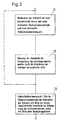
- FIG. 2 shows a flowchart of a further embodiment variant of the method according to the invention for determining the viscosity.
- This embodiment variant differs considerably from the embodiment described above with reference to FIG. 1, as in the embodiment according to FIG. 2 the outlet of the pump is not closed, but the determination of the viscosity with the pump outlet open, ie quasi "on line ". Following this flowchart may run a second series of process variants in which the pump outlet is opened.
- Modulating the rated speed of the rotor during pumping with a sufficiently high modulation (circle) frequency and a defined modulation amplitude the modulation of the speed causes due to the inertia of the liquid at the outlet of the pump, no change in pressure or flow, the pump power remains practical unchanged.
- the modulation frequency is chosen so that the modulation does not affect the pressure or flow fluctuations at the outlet of the pump. Instead, the power supplied by the modulation is completely converted into frictional losses by liquid friction. However, these friction losses are again dependent on the viscosity of the liquid.
- the viscosity function described in equation (VI) can in turn be measured for each pump, and e.g. in the form of a look-up table, for example, stored in the memory of a microprocessor.
- a look-up table for the respective pump has already been detected before the operation of the pump and stored in the memory of the microprocessor.
- this embodiment of the method according to the invention for determining the viscosity is such that in a first step 21 the rotational speed of the pump rotor is modulated around a nominal rotational speed n 0 with a defined modulation amplitude ⁇ n and a defined modulation circular frequency ⁇ m (see equation (III))
- the modulation frequency is chosen so high that due to the inertia of the liquid, the speed modulation at the outlet of the pump has no change in pressure or flow result.
- a fluctuation of the drive torque is caused around an average drive torque M A0 , with an amplitude ⁇ M A and the same frequency ⁇ m as the modulation angular frequency of the rotational speed (see relationship (IV)).
- This amplitude can be measured in a step 22, namely as the amplitude of the fluctuation of the drive current, the drive torque is directly proportional, so that from the measurement of the amplitude of the fluctuation of the drive current, the amplitude of the fluctuation of the drive torque can be easily calculated.
- a step 23 with the aid of the lookup table stored in the memory of the microprocessor, it is determined which viscosity results from the values for the modulation amplitude ⁇ n of the rotational speed and the amplitude ⁇ M A of the fluctuation of the drive torque. If the value for the amplitude of the fluctuation of the drive torque measured in step 22 and the modulation amplitude for the rotational speed are not exactly present in the look-up table in the memory of the microprocessor, conventional interpolation methods are used.
- the function in relation (IV) is - as can be seen - dependent on the modulation (circle) frequency ⁇ m .
- ⁇ M / ⁇ modulation circuit frequencies of about 100 rad / s to about 500 rad / s.
- the drive torque can also be modulated and the amplitude of the resulting rotational speed fluctuation can be measured, and these two values can then be used to determine the viscosity.
- the amplitude of the speed variation can be measured either directly via a speed measurement or via the voltage on the rotor, which is approximately directly proportional to the speed (see above) and therefore can be easily calculated from the voltage on the rotor.
- This type of viscosity determination is also suitable for pumps with a magnetic bearing of the rotor.
- Pumps, in particular blood pumps, with a magnetic bearing of the rotor are for example in the WO-A-96/31934 described.
Description
Die Erfindung betrifft ein Verfahren zur Bestimmung der Viskosität einer Flüssigkeit, z.B. von Blut, die von einer Pumpe, z.B. einer Blutpumpe gefördert wird, gemäss dem Oberbegriff des unabhängigen Patentanspruchs.The invention relates to a method for determining the viscosity of a liquid, e.g. of blood coming from a pump, e.g. a blood pump is funded, according to the preamble of the independent claim.
Pumpen, insbesondere Blutpumpen, die beispielsweise in Herz-Lungen-Maschinen zum Einsatz kommen (als Ersatz für die Pumpfunktion des Herzens), haben einen Einlass und einen Auslass für die zu fördernde Flüssigkeit, hier also das Blut. Weiterhin haben solche Pumpen einen Rotor, der die zu fördernde Flüssigkeit, hier also das Blut, vom Einlass zum Auslass fördert. Speziell bei Blutpumpen, die in Herz-Lungen-Maschinen zum Einsatz kommen, ist eine der Grössen, die ständig überwacht werden müssen, die Viskosität des Bluts. Aber auch bei anderen Pumpen als Blutpumpen kann die Überwachung der Viskosität erforderlich bzw. wünschenswert sein.Pumps, in particular blood pumps, which are used for example in heart-lung machines (as a replacement for the pumping function of the heart), have an inlet and an outlet for the liquid to be pumped, in this case the blood. Furthermore, such pumps have a rotor, which promotes the liquid to be conveyed, in this case the blood, from the inlet to the outlet. Especially with blood pumps that are used in heart-lung machines, one of the sizes that must be constantly monitored is the viscosity of the blood. But even with pumps other than blood pumps, the monitoring of the viscosity may be required or desirable.
In Dokument
In Dokument
Eine Blutpumpe, bei der es möglich ist, die Viskosität des Bluts zu bestimmen, ist beispielsweise aus der
Die Viskositätsbestimmung wird gemäss der
Diese Blutpumpe bzw. die beschriebene Vorgehensweise ist insofern nachteilig, als eine aktiv regelbare axiale Lagerung des Pumpenrotors vorgesehen sein muss, um das Störsignal über die aktive Lagerung einprägen zu können. Dagegen ist es nicht möglich, die Viskosität auf die oben beschriebene Art und Weise mit Pumpen zu bestimmen, bei denen die axiale Lagerung des Rotors mechanisch ist, weil die mechanische Lagerung des Rotors in axialer Richtung starr ist, sodass eine Auslenkung des Rotors in axialer Richtung nicht stattfinden kann. Auch bei passiven axialen magnetischen Lagerungen, bei denen der Rotor in axialer Richtung durch Reluktanzkräfte gelagert wird, ist eine Bestimmung der Viskosität des Bluts auf diese Weise nicht möglich, weil eine aktive Ansteuerung der Lagerung bei passiven Lagern - die Eigenschaft "passiv" besagt genau dies - eben nicht möglich ist. Somit ist die beschriebene Vorgehensweise nur für Pumpen mit einer aktiven axialen magnetischen Lagerung des Rotors geeignet, für Pumpen mit in axialer Richtung mechanisch gelagerten Rotoren wie auch für Pumpen mit passiven axialen magnetischen Lagerungen ist die beschriebene Vorgehensweise nicht geeignet.This blood pump or the procedure described is disadvantageous in that an actively controllable axial bearing of the pump rotor has to be provided in order to be able to impress the interfering signal via the active bearing. On the other hand, it is not possible to reduce the viscosity to to determine the manner described above with pumps in which the axial bearing of the rotor is mechanical, because the mechanical mounting of the rotor in the axial direction is rigid, so that a deflection of the rotor in the axial direction can not take place. Even with passive axial magnetic bearings in which the rotor is mounted in the axial direction by reluctance forces, a determination of the viscosity of the blood in this way is not possible because an active activation of the storage in passive storage - the property "passive" says just that - just is not possible. Thus, the described procedure is only suitable for pumps with an active axial magnetic bearing of the rotor, for Pumps with rotors mechanically mounted in the axial direction as well as pumps with passive axial magnetic bearings, the described procedure is not suitable.
Es ist daher eine Aufgabe der Erfindung, ein Verfahren vorzuschlagen, mit welchem es möglich ist, bei einer Pumpe, z.B. einer Blutpumpe, mit möglichst geringem Aufwand die Viskosität der geförderten Flüssigkeit, z.B. Blut, bestimmen zu können, wobei die Art der Lagerung des Rotors, insbesondere die Art der axialen Lagerung, frei wählbar sein soll. Insbesondere soll das Verfahren natürlich geeignet sein für magnetische Lagerungen des Rotors, die bei Blutpumpen typischerweise zum Einsatz kommen.It is therefore an object of the invention to propose a method with which it is possible to use a pump, e.g. a blood pump, with as little effort as possible the viscosity of the delivered liquid, e.g. Blood to determine, with the type of storage of the rotor, in particular the type of axial storage, should be freely selectable. In particular, the method should of course be suitable for magnetic bearings of the rotor, which are typically used in blood pumps.
Diese Aufgabe wird mit Hilfe eines Verfahrens gelöst, wie es durch die Merkmale des unabhängigen Patentanspruchs charakterisiert ist. Besonders vorteilhafte Varianten des Verfahrens ergeben sich aus den Merkmalen der abhängigen Patentansprüche.This object is achieved by means of a method as characterized by the features of the independent claim. Particularly advantageous variants of the method emerge from the features of the dependent claims.
Zur Bestimmung der Viskosität einer Flüssigkeit, z.B. von Blut, die von einer Pumpe, z.B. einer Blutpumpe, gefördert wird, welche Pumpe einen Rotor zur Förderung der Flüssigkeit vom Einlass der Pumpe zum Auslass aufweist, wird ebenfalls der Rotor zur Bestimmung der Viskosität herangezogen. Jedoch erfolgt zur Bestimmung der Viskosität der Flüssigkeit keine aktive Anregung des Rotors zur axialen Auslenkung aus seiner Betriebsposition, sondern der Rotor wird in seiner Betriebsposition belassen und die Viskosität wird aus Messgrössen der Pumpe bzw. des Rotors bestimmt. Somit ist die Art der Lagerung des Rotors, insbesondere die Art der axialen Lagerung des Rotors, frei wählbar. Speziell ist das Verfahren natürlich auch für magnetische Lagerungen des Rotors geeignet, wie sie bei Blutpumpen typischerweise zum Einsatz kommen, insbesondere auch für passive axiale magnetische Lagerungen des Rotors.In order to determine the viscosity of a fluid, eg of blood which is conveyed by a pump, for example a blood pump, which pump has a rotor for conveying the fluid from the inlet of the pump to the outlet, the rotor is also used to determine the viscosity. However, to determine the viscosity of the liquid no active excitation of the rotor for axial deflection from its operating position, but the rotor is left in its operating position and the viscosity is determined from measured variables of the pump or the rotor. Thus, the nature of the bearing of the rotor, in particular the type of axial bearing of the rotor, freely selectable. Of course, the method is of course also suitable for magnetic bearings of the rotor, as are typically used in blood pumps, in particular for passive axial magnetic bearings of the rotor.
Als Messgrössen können das Antriebsmoment bzw. der Antriebsstrom des Rotors und/oder die Rotordrehzahl gemessen werden. Dies sind Grössen, die leicht ausserhalb der Pumpe gemessen werden können. Dies gilt sowohl für das Antriebsmoment des Rotors (oder exakter: des Motors, der den Rotor antreibt), da das Antriebsmoment dem Antriebsstrom näherungsweise direkt proportional ist und für absolute Exaktheit über einen bekannten funktionellen Zusammenhang ermittelt werden kann, als auch für die Drehzahl, die der Spannung am Rotor näherungsweise proportional ist (und für absolute Exaktheit über einen bekannten funktionellen Zusamenhang ermittelt werden kann), sodass für die Praxis die Spannung am Rotor (oder exakter: am Motor, der den Rotor antreibt) als Mass für die Drehzahl gemessen werden kann. Bei drehzahlgeregelten Motoren, das sind Motoren, die auf eine konstante Drehzahl hin geregelt werden, genügt es prinzipiell, nur das Antriebsmoment zu messen (die Drehzahl ist in etwa konstant). Bei momentgeregelten Motoren, das sind Motoren, die auf ein konstantes Antriebsmoment bzw. einen konstanten Antriebsstrom hin geregelt werden, genügt es prinzipiell, nur die Drehzahl zu messen (das Antriebsmoment bzw. der Antriebsstrom ist in etwa konstant). Natürlich ist es immer möglich und natürlich die exakte Vorgehensweise, sowohl die Drehzahl als auch das Antriebsmoment bzw. den Antriebsstrom zu messen. Aus den Werten für Antriebsmoment bzw. Antriebsstrom und/oder Rotordrehzahl wird dann die Viskosität der Flüssigkeit bestimmt.As measured variables, the drive torque or the drive current of the rotor and / or the rotor speed can be measured. These are sizes that can be easily measured outside the pump. This applies to both the drive torque of the rotor (or more precisely: the motor that drives the rotor), since the drive torque is approximately directly proportional to the drive current and can be determined for absolute accuracy on a known functional relationship, as well as for the speed The voltage across the rotor is approximately proportional (and can be determined for absolute accuracy via a known functional correlation), so that in practice the voltage on the rotor (or more precisely on the motor that drives the rotor) can be measured as a measure of the speed , For variable speed motors, which are motors that are controlled to a constant speed, it is sufficient in principle, only the drive torque to measure (the speed is approximately constant). In torque-controlled motors, which are motors that are controlled to a constant drive torque or a constant drive current out, it is sufficient in principle to measure only the speed (the drive torque or the drive current is approximately constant). Of course it is always possible and of course the exact procedure to measure both the speed and the drive torque or the drive current. The viscosity of the liquid is then determined from the values for drive torque or drive current and / or rotor speed.
Dabei können zur Bestimmung der Viskosität mehrere Messungen von Antriebsmoment bzw. Antriebsstrom und/oder Rotordrehzahl durchgeführt werden, sodass mehrere (einzelne) Werte für die Viskosität bestimmt werden. Aus diesen mehreren Werten für die Viskosität wird dann eine mittlere Viskosität bestimmt, welche dann den Wert für die Viskosität darstellt. Dadurch lässt sich die Genauigkeit des Werts für die Viskosität erhöhen.Several measurements of drive torque or drive current and / or rotor speed can be carried out to determine the viscosity, so that several (individual) values for the viscosity are determined. From these several values of viscosity, an average viscosity is determined, which then represents the value for the viscosity. This can increase the accuracy of the value for the viscosity.
Weitere Verfahrensvarianten unterscheiden sich dadurch, dass sie entweder bei geschlossenem Aulass der Pumpe durchgeführt werden oder bei geöffnetem Auslass der Pumpe, also quasi "on-line".Other variants of the method differ in that they are carried out either when the pump is closed or when the pump is open, that is to say virtually "on-line".
Bei einer ersten Reihe von vorteilhaften Verfahrensvarianten wird vor der Bestimmung der Viskosität mit Hilfe der Messgrössen der Pumpenauslass geschlossen. Während einer Herzoperation muss der Auslass operationsbedingt ohnehin mehrmals abgeklemmt werden, sodass die Zeit, in der der Auslass geschlossen ist, für die Bestimmung der Viskosität genutzt werden kann.In a first series of advantageous method variants, the pump outlet is closed before the viscosity is determined with the aid of the measured variables. During cardiac surgery, the outlet must be disconnected several times for operational reasons anyway, so that the time in which the outlet is closed can be used to determine the viscosity.
Hierbei können die Messungen von Antriebsmoment bzw. Antriebsstrom und/oder Rotordrehzahl durch ein Auslösesignal bewirkt werden, welches nach dem Schliessen des Pumpenauslasses an eine Steuerung weitergeleitet wird, welche dann die Messungen von Antriebsmoment bzw. Antriebsstrom und/oder Rotordrehzahl initiiert.Here, the measurements of drive torque or drive current and / or rotor speed can be effected by a trigger signal, which is forwarded after closing the pump outlet to a controller, which then initiates the measurements of drive torque or drive current and / or rotor speed.
Ein solches Auslösesignal kann beispielsweise von einer Schliessvorrichtung zum Verschliessen des Pumpenauslasses, z.B. einem Ventil, erzeugt und an die Steuerung geleitet werden, sobald der Pumpenauslass geschlossen ist.Such a triggering signal may, for example, be provided by a closing device for closing the pump outlet, e.g. a valve, are generated and sent to the controller as soon as the pump outlet is closed.
Eine andere Möglichkeit besteht darin, dass das Auslösesignal von einer Durchflussmessvorrichtung, die am Pumpenauslass angeordnet ist, erzeugt und an die Steuerung geleitet wird, sobald kein Durchfluss mehr am Pumpenauslass festgestellt wird. Wenn kein Durchfluss mehr am Pumpenauslass festgestellt wird, bedeutet dies, dass der Pumpenauslass geschlossen ist und die Messungen von Antriebsmoment bzw. Antriebsstrom und/oder Rotordrezahl zur Bestimmung der Viskosität können initiiert werden.Another possibility is that the trigger signal from a flow meter, which is arranged at the pump outlet, is generated and sent to the controller when no more flow is detected at the pump outlet. If no flow is detected at the pump outlet, this means that the pump outlet is closed and the measurements of the drive torque or drive current and / or rotor speed for determining the viscosity can be initiated.
Wieder eine andere Möglichkeit besteht darin, dass das Auslösesignal von einer Druckmessvorrichtung, die am Pumpenauslass angeordnet ist, erzeugt und an die Steuerung geleitet wird, sobald am Pumpenauslass ein Druck festgestellt wird, der bei gegebener Rotordrehzahl einen Schwellenwert überschreitet. Auch das Überschreiten dieses Schwellendrucks bedeutet, dass der Pumpenauslass geschlossen ist und dass die Messungen von Antriebsmoment bzw. Antriebsstrom und/oder Rotordrehzahl zur Bestimmung der Viskosität initiiert werden können.Yet another possibility is that the triggering signal from a pressure measuring device, which is arranged at the pump outlet, is generated and sent to the controller as soon as a pressure is detected at the pump outlet, which exceeds a threshold at a given rotor speed. Exceeding this threshold pressure means that the pump outlet is closed and that the measurements of drive torque or drive current and / or rotor speed can be initiated to determine the viscosity.
Weiterhin kann bei einer Pumpe mit Drehzahlregelung ein nach dem Schliessen des Pumpenauslasses auftretender schlagartiger Abfall des Antriebsmoments erkannt und daraufhin das Auslösesignal an die Steuerung geleitet werden. Bei einer Pumpe mit Drehzahlregelung fällt nämlich nach dem Schliessen des Pumpenauslasses das Antriebsmoment bzw. der Antriebsstrom des Rotors schlagartig ab, weil kein Blut mehr gefördert werden kann und das in der Pumpe befindliche Blut sehr schnell die gleiche Geschwindigkeit aufweist wie der Pumpenrotor, sodass zur Aufrechterhaltung dieser Geschwindigkeit nur noch ein geringes Antriebsmoment bzw. ein geringer Antriebsstrom erforderlich ist.Furthermore, in the case of a pump with speed control, an abrupt drop in the drive torque occurring after closing the pump outlet can be detected, and then the trigger signal can be sent to the controller. In a pump with speed control namely after the closing of the pump outlet, the drive torque or the drive current of the rotor abruptly because no more blood can be promoted and the blood in the pump very quickly has the same speed as the pump rotor, so to maintain This speed only a small drive torque or a low drive current is required.
Umgekehrt kann bei einer Pumpe mit Antriebsmomentregelung bzw. Antriebsstromregelung ein nach dem Schliessen des Pumpenauslasses schlagartig auftretender Anstieg der Drehzahl erkannt werden und daraufhin das Auslösesignal an die Steuerung geleitet werden. Bei einer Pumpe mit Antriebsmomentregelung bzw. Antriebsstromregelung steigt nämlich nach dem Schliessen des Pumpenauslasses die Drehzahl sehr schnell an, weil kein Blut mehr gefördert werden kann und das in der Pumpe befindliche Blut sehr schnell die gleiche Drehzahl aufweist wie der Rotor, sodass zur Aufrechterhaltung dieser Geschwindigkeit nur noch ein geringes Antriebsmoment bzw. ein geringer Antriebsstrom erforderlich ist. Gleichwohl steht nach wie vor das gleiche Antriebsmoment bzw. der gleiche Antriebsstrom zur Verfügung wie bei geöffnetem Pumpenauslass, was eine Beschleunigung des Rotors (Drehzahlanstieg) und der Flüssigkeit zur Folge hat.Conversely, in a pump with drive torque control or drive current control after the closing of the Pumpenauslasses abruptly occurring increase in speed can be detected and then the trigger signal are passed to the controller. In a pump with drive torque control or drive current control namely increases after closing the pump outlet, the speed very quickly, because no more blood can be promoted and the blood in the pump very quickly the same speed as the rotor, so to maintain this speed only a small drive torque or a low drive current is required. nevertheless the same drive torque or drive current is still available as with the pump outlet open, which results in an acceleration of the rotor (speed increase) and of the fluid.
Bei einer zweiten Reihe von vorteilhaften Verfahrensvarianten werden die Messungen von Antriebsmoment bzw. Antriebsstrom und/oder Rotordrehzahl bei geöffnetem Pumpeneinlass und geöffnetem Pumpenauslass durchgeführt, also quasi "on-line" während des Betriebs. Diese Verfahrensvariante ist zu jeder beliebigen Zeit (z.B. zu jedem beliebigen Zeitpunkt während einer Herzoperation) durchführbar, ausser eben dann, wenn der Pumpenauslass geschlossen ist.In a second series of advantageous method variants, the measurements of drive torque or drive current and / or rotor speed are carried out with the pump inlet open and the pump outlet open, that is to say quasi "on-line" during operation. This variant of the method is feasible at any time (e.g., at any time during cardiac surgery) except when the pump outlet is closed.
Bei dieser Verfahrensvariante kann die Bestimmung der Viskosität derart erfolgen, dass die Rotordrehzahl um eine Nenndrehzahl herum mit einer Modulationsamplitude und einer Modulationsfrequenz moduliert wird, wobei am Auslass der Pumpe durch die Modulation praktisch keine oder nur eine geringe Änderung des Durchflusses erzeugt wird. Aufgrund der Trägheit der Flüssigkeit erfolgt im wesentlichen keine Durchflussänderung, jedoch wird durch die Modulation eine Schwankung des Antriebsmoments bzw. des Antriebsstroms hervorgerufen. Aus der Modulationsamplitude der Drehzahl und der daraus resultierenden Amplitude der Schwankung des Antriebsmoments bzw. des Antriebsstroms wird dann die Viskosität bestimmt.In this variant of the method, the determination of the viscosity can be such that the rotor speed is modulated by a rated speed around with a modulation amplitude and a modulation frequency, wherein at the outlet of the pump by the modulation practically no or only a small change in the flow is generated. Due to the inertia of the liquid is essentially no change in flow, but is caused by the modulation, a fluctuation of the drive torque or the drive current. From the modulation amplitude of the speed and the resulting amplitude of the fluctuation of the drive torque or the drive current, the viscosity is then determined.
Die Bestimmung der Viskosität kann auch derart erfolgen, dass das Antriebsmoment bzw. der Antriebsstrom um ein Nennantriebsmoment bzw. einen Nennantriebstrom herum mit einer Modulationsamplitude und einer Modulationsfrequenz moduliert wird, wobei am Auslass der Pumpe durch die Modulation praktisch keine oder nur eine geringe Änderung des Durchflusses erzeugt wird, jedoch eine Schwankung der Drehzahl hervorgerufen wird.The determination of the viscosity can also be such that the drive torque or the drive current is modulated by a nominal drive torque or a nominal drive current around with a modulation amplitude and a modulation frequency, wherein at the outlet of the pump by the modulation virtually no or only a small change in the flow is generated, however, a fluctuation of the rotational speed is caused.
Auch hier erfolgt also aufgrund der Trägheit der Flüssigkeit im wesentlichen keine Durchflussänderung. Aus der Modulationsamplitude des Antriebsmoments bzw. des Antriebsstroms und der daraus resultierenden Amplitude der Schwankung der Drehzahl wird dann die Viskosität bestimmt.Again, therefore, due to the inertia of the liquid is essentially no change in flow. The viscosity is then determined from the modulation amplitude of the drive torque or the drive current and the resulting amplitude of the fluctuation of the rotational speed.
Da sämtliche vorstehend beschriebenen Verfahrensvarianten speziell auch für Blutpumpen geeignet sind, wird vorteilhafterweise eine Pumpe mit einer magnetischen Lagerung des Rotors verwendet, wie dies bei Blutpumpen (aus mehreren Gründen, z.B. Kontamination) typischerweise der Fall ist.Since all of the process variants described above are also particularly suitable for blood pumps, a pump with a magnetic bearing of the rotor is advantageously used, as is typically the case with blood pumps (for several reasons, for example contamination).
Nachfolgend wird das erfindungsgemässe Verfahren zur Bestimmung der Viskosität anhand der Zeichung näher erläutert, in der die beiden vorstehend bereits angesprochenen Ausführungsvarianten - nämlich einerseits bei geschlossenem Ausgang der Pumpe und andererseits bei geöffnetem Ausgang der Pumpe, also quasi "on-line" - dargestellt sind. Es zeigen in schematischer Darstellung:
- Fig. 1
- eine erste Ausführungsvariante des erfindungsgemässen Verfahrens zur Bestimmung der Viskosität in Form eines Ablaufdiagramms (bei geschlossenem Auslass der Pumpe)
und - Fig. 2
- eine zweite Ausführungsvariante des erfindungsgemässen Verfahrens zur Bestimmung der Viskosität in Form eines Ablaufdiagramms (bei geöffnetem Auslass der Pumpe, also quasi "on-line").
- Fig. 1
- a first embodiment of the method according to the invention for determining the viscosity in the form of a flow chart (with the outlet of the pump closed)
and - Fig. 2
- a second embodiment of the inventive method for determining the viscosity in the form of a flow chart (with the outlet of the pump open, so almost "on-line").
In Fig. 1 ist ein Ablaufdiagramm einer Verfahrensvariante des erfindungsgemässen Verfahrens zur Bestimmung der Viskosität dargestellt.1 shows a flowchart of a process variant of the method according to the invention for determining the viscosity.
Nach diesem Ablaufdiagramm können eine erste Reihe von Verfahrensvarianten ablaufen, bei dnen die Bestimmung der Viskosität bei geschlossenem Pumpenauslass erfolgt.After this flowchart, a first series of process variants can proceed, in which the determination of the viscosity takes place with the pump outlet closed.
Dazu soll vorausgeschickt werden, dass für das Reibmoment von Flüssigkeiten in Pumpen vereinfacht folgende Beziehung gilt: ![]()
worin die einzelnen Variablen folgendes bedeuten:
- MR
- das Reibmoment einer Flüssigkeit,
- KG
- einen Geometriefaktor,
- η
- die dynamische Viskosität der Flüssigkeit,
- ω
- die Kreisfrequenz des Pumpenrotors.
wherein the individual variables mean:
- M R
- the frictional moment of a liquid,
- K G
- a geometry factor,
- η
- the dynamic viscosity of the liquid,
- ω
- the angular frequency of the pump rotor.
Bei geschlossenem Pumpenauslass wird der Durchfluss durch die Pumpe null, mit anderen Worten heisst dies, dass die gesamte Antriebsleistung in Flüssigkeitsreibung umgesetzt wird, das Antriebsmoment also dem Reibmoment entspricht: 
- MA
- Antriebsmoment
- MR
- Reibmoment,
- M A
- drive torque
- M R
- friction torque,
In der Praxis sind die Verhältnisse in einer Pumpe etwas komplexer (aufgrund von turbulenter Strömung etc.), dennoch gibt es einen eindeutigen funktionellen Zusammenhang zwischen der Viskosität, der Rotordrehzahl (bzw. der Kreisfrequenz) und dem Antriebsmoment: 
Dieser funktionelle Zusammenhang kann für jede Pumpe messtechnisch erfasst werden und z.B. in Form einer Nachschlagetabelle ("look-up-table") beispielsweise im Speicher eines Mikroprozessors abgelegt werden. Bei dieser Ausführungsvariante des erfindungsgemässen Verfahrens ist eine solche Nachschlagetabelle für die jeweilige Pumpe vor dem Betrieb der Pumpe bereits erfasst und im Speicher des Mikroprozessors abgelegt worden.This functional relationship can be metrologically detected for each pump and e.g. in the form of a look-up table, for example, stored in the memory of a microprocessor. In this embodiment variant of the method according to the invention, such a look-up table for the respective pump has already been detected before the operation of the pump and stored in the memory of the microprocessor.
Gemäss Fig. 1 läuft dieses Ausführungsbeispiel des Verfahrens zur Bestimmung der Viskosität derart ab, dass in einem ersten Schritt 11 mittels einer Schliessvorrichtung der Auslass der Pumpe geschlossen wird. Während einer Herzoperation muss der Auslass einer solchen Pumpe, die z.B. in einer Herz-Lungen-Maschine eingesetzt wird, operationsbedingt ohnehin mehrmals abgeklemmt werden, sodass die Zeit, in der der Auslass geschlossen ist, für die Bestimmung der Viskosität genutzt werden kann.According to FIG. 1, this exemplary embodiment of the method for determining the viscosity proceeds in such a way that in a
Ist der Auslass geschlossen, so kann die Messung von Antriebsmoment bzw. Antriebsstrom und/oder Rotordrehzahl mit Hilfe eines Auslösesignals, welches an eine Steuerung geleitet wird, initiiert werden. Bei einer Pumpe mit Drehzahlregelung (also mit einer Regelung auf eine konstante Drehzahl hin) genügt es prinzipiell, wenn das Antriebsmoment bzw. der Antriebsstrom gemessen wird (die Drehzahl ist ja in etwa konstant), bei einer Pumpe mit Regelung des Antriebsmoments bzw. des Antriebsstroms (also mit einer Regelung auf ein konstantes Antriebsmoment bzw. auf einen konstanten Antriebsstrom hin) genügt es prinzipiell, die Drehzahl zu messen (das Antriebsmoment bzw. der Antriebsstrom ist ja konstant). Natürlich ist es möglich und auch exakt, sowohl das Antriebsmoment bzw. den Antriebsstrom als auch die Drehzahl zu messen. Damit ein Auslösesignal zur Initiierung eines Messvorgangs erzeugt werden kann, muss zunächst in einem Schritt 12 erkannt werden, dass der Auslass der Pumpe geschlossen ist. Ein solches Auslösesignal kann beispielsweise von der Schliessvorrichtung selbst, z.B. einem (elektrisch betätigbaren) Ventil der Herz-Lungen-Maschine, erzeugt und an die Steuerung geleitet werden, sobald der Pumpenauslass geschlossen ist.If the outlet is closed, the measurement of drive torque or drive current and / or rotor speed can be initiated with the aid of a trigger signal, which is sent to a controller. In a pump with speed control (ie with a control to a constant speed out) it is sufficient in principle, if the drive torque or the drive current is measured (the speed is indeed approximately constant), with a pump with Control of the drive torque or the drive current (ie with a control to a constant drive torque or to a constant drive current out) it is sufficient in principle to measure the speed (the drive torque or the drive current is indeed constant). Of course, it is possible and also accurate to measure both the drive torque and the drive current and the speed. So that a triggering signal for initiating a measuring process can be generated, it must first be detected in a
Eine andere Möglichkeit besteht darin, eine Durchflussmessvorrichtung am Pumpenauslass vorzusehen, welche das Auslösesignal erzeugt und an die Steuerung leitet, sobald kein Durchfluss mehr am Pumpenauslass festgestellt wird. Dies bedeutet nämlich, dass der Pumpenauslass geschlossen ist.Another possibility is to provide a flow measuring device at the pump outlet, which generates the trigger signal and sends it to the controller as soon as no more flow is detected at the pump outlet. This means that the pump outlet is closed.
Wieder eine andere Möglichkeit besteht darin, eine Druckmessvorrichtung am Pumpenauslass vorzusehen, welche das Auslösesignal erzeugt und an die Steuerung leitet, sobald am Pumpenauslass ein Druck festgestellt wird, der bei gegebener Rotordrehzahl einen Schwellenwert überschreitet. Das Überschreiten dieses Schwellendrucks bedeutet, dass der Pumpenauslass geschlossen ist.Yet another possibility is to provide a pressure measuring device at the pump outlet which generates the triggering signal and directs it to the controller as soon as a pressure is detected at the pump outlet which exceeds a threshold at a given rotor speed. Exceeding this threshold pressure means that the pump outlet is closed.
Weiterhin kann der geschlossene Auslass bei einer Pumpe mit Drehzahlregelung (also bei einer Pumpe, die auf eine konstante Drehzahl hin geregelt ist) durch einen nach dem Schliessen des Pumpenauslasses auftretenden schlagartigen Abfall des Antriebsmoments erkannt und daraufhin das Auslösesignal an die Steuerung geleitet werden. Bei einer Pumpe mit Drehzahlregelung fällt nämlich nach dem Schliessen des Pumpenauslasses das Antriebsmoment bzw. der Antriebsstrom des Rotors schlagartig ab, weil kein Blut mehr gefördert werden kann und das in der Pumpe befindliche Blut sehr schnell die gleiche Drehgeschwindigkeit aufweist wie der Pumpenrotor, sodass zur Aufrechterhaltung dieser Drehgeschwindigkeit nur noch ein geringes Antriebsmoment bzw. ein geringer Antriebsstrom erforderlich ist.Furthermore, in the case of a pump with closed-loop speed control (ie in the case of a pump which is regulated to a constant rotational speed), the closed outlet can be detected by a sudden drop in the drive torque occurring after the pump outlet closes and the triggering signal can then be sent to the controller. At a Pump with speed control falls namely after the closing of the pump outlet, the drive torque or the drive current of the rotor abruptly, because no more blood can be pumped and the blood in the pump very quickly has the same rotational speed as the pump rotor, so to maintain this rotational speed only a small drive torque or a low drive current is required.
Umgekehrt kann der geschlossene Auslass bei einer Pumpe mit Antriebsmomentregelung bzw. Antriebsstromregelung (also bei einer Pumpe, die auf ein konstantes Antriebsmoment bzw. auf einen konstanten Antriebsstrom hin geregelt ist) durch einen nach dem Schliessen des Pumpenauslasses schlagartig auftretenden Anstieg der Drehzahl erkannt werden und daraufhin das Auslösesignal an die Steuerung geleitet werden. Bei einer Pumpe mit Antriebsmomentregelung bzw. Antriebsstromregelung steigt nämlich nach dem Schliessen des Pumpenauslasses die Drehzahl sehr schnell an, weil kein Blut mehr gefördert werden kann und das in der Pumpe befindliche Blut sehr schnell die gleiche Drehzahl aufweist wie der Rotor, sodass zur Aufrechterhaltung dieser Geschwindigkeit nur noch ein geringes Antriebsmoment bzw. ein geringer Antriebsstrom erforderlich ist. Gleichwohl steht nach wie vor das gleiche Antriebsmoment bzw. der gleiche Antriebsstrom zur Verfügung wie bei geöffnetem Pumpenauslass, was eine Beschleunigung des Rotors (Drehzahlanstieg) und der Flüssigkeit zur Folge hat.Conversely, the closed outlet in a pump with drive torque control or drive current control (that is, in a pump that is controlled to a constant drive torque or to a constant drive current) can be detected by an abruptly occurring after the closing of the pump outlet increase in speed and then the trigger signal will be sent to the controller. In a pump with drive torque control or drive current control namely increases after closing the pump outlet, the speed very quickly, because no more blood can be promoted and the blood in the pump very quickly the same speed as the rotor, so to maintain this speed only a small drive torque or a low drive current is required. Nevertheless, the same drive torque or drive current is still available as when the pump outlet is open, which results in an acceleration of the rotor (speed increase) and of the fluid.
Nachdem der geschlossene Auslass der Pumpe in Schritt 12 erkannt und das Auslösesignal für die Messungen von Antriebsmoment und Rotordrehzahl in Schritt 13 ausgelöst worden ist, wird von der Steuerung die Messung von Antriebsmoment und/oder Drehzahl initiiert.After the closed outlet of the pump has been detected in
Die Messung von Antriebsmoment und/oder Rotordrehzahl erfolgt in einem Schritt 14. Das Antriebsmoment kann dabei derart gemessen werden, dass der Antriebsstrom des Motors, der den Pumpenrotor antreibt, gemessen wird. Der Antriebsstrom ist dem Antriebsmoment näherungsweise direkt proportional (siehe oben), weshalb der Antriebsstrom für die Praxis ein direktes Mass für das Antriebsmoment ist und das Antriebsmoment leicht aus dem gemessenen Wert für den Antriebsstrom berechnet werden kann. Die Rotordrehzahl kann entweder direkt mittels einer an sich bekannten Drehzahlmesseinrichtung gemessen werden, oder es kann die Antriebsspannung des Motors, der den Pumpenrotor antreibt, gemessen werden. Die Antriebsspannung ist der Rotordrehzahl näherungsweise direkt proportional (siehe oben), weshalb die Antriebsspannung ein direktes Mass für die Rotordrehzahl ist und die Rotordrehzahl leicht aus der Antriebsspannung berechnet werden kann. Nach Durchführung der Messungen in Schritt 14 liegen also die Werte für das Antriebsmoment und die Rotordrehzahl vor.The measurement of drive torque and / or rotor speed takes place in a step 14. The drive torque can be measured in such a way that the drive current of the motor which drives the pump rotor is measured. The drive current is approximately directly proportional to the drive torque (see above), which is why the drive current in practice is a direct measure of the drive torque and the drive torque can be easily calculated from the measured value for the drive current. The rotor speed can be measured either directly by means of a per se known speed measuring device, or it can be the drive voltage of the motor which drives the pump rotor, are measured. The drive voltage is approximately directly proportional to the rotor speed (see above), which is why the drive voltage is a direct measure of the rotor speed and the rotor speed can be easily calculated from the drive voltage. After carrying out the measurements in step 14, the values for the drive torque and the rotor speed are therefore present.
Nun wird in einem Schritt 15 mit Hilfe des Mikroprozessors in der Nachschlagetabelle ("look-up-table") nachgesehen, welche Viskosität aus den gemessenen Werten für Antriebsstrom und Drehzahl resultiert. Sind dabei die in Schritt 14 gemessenen Werte für Antriebsmoment und Rotordrehzahl nicht genau in der Nachschlagetabelle im Speicher des Mikroprozessors vorhanden, so kommen übliche Interpolationsverfahren zum Einsatz.Now in a
Es können auch mehrere Messungen von Antriebsmoment bzw. Antriebsstrom und Rotordrehzahl durchgeführt werden (siehe gestrichelte Linie inFig. 1), z.B. während eines Hochlaufs der Pumpe von null auf die Nenndrehzahl. Entsprechend können auch mehrere Werte für die Viskosität bestimmt werden. Aus diesen mehreren Werten für die Viskosität kann dann durch Mittelungsverfahren eine mittlere Viskosität bestimmt werden, die dann den endgültigen Wert für die Viskosität darstellt, der nach Schritt 15 als ermittelte Viskosität ausgegeben wird. Diese Vorgehensweise erhöht die Genauigkeit der Viskositätsbestimmung.It is also possible to carry out several measurements of drive torque and rotor speed (see dashed line in FIG. 1), eg during a run-up of the pump from zero to the rated speed. Accordingly, several values for the viscosity can be determined. From these several values for the viscosity can then averaging viscosity is determined by averaging method, which then represents the final value for the viscosity which is output after
Besonders geeignet ist diese Art der Viskositätsbestimmung für Pumpen mit einer magnetischen Lagerung des Rotors, weil dann der Einfluss von Lagerreibung, der bei mechanischen Lagern berücksichtigt werden muss, nicht auftritt. Pumpen, insbesondere Blutpumpen, mit einer magnetischen Lagerung des Rotors sind beispielsweise in der
In Fig. 2 ist ein Ablaufdiagramm einer weiteren Ausführungsvariante des erfindungsgemässen Verfahrens zur Bestimmung der Viskosität dargestellt. Diese Ausführungsvariante unterscheidet sich insofern wesentlich von der Ausführungsvariante, die oben anhand von Fig. 1 beschrieben ist, als bei der Ausführungsvariante gemäss Fig. 2 der Auslass der Pumpe nicht geschlossen ist, sondern die Bestimmung der Viskosität bei geöffnetem Pumpenauslass, also quasi "on-line" erfolgt. Nach diesem Ablaufdiagramm können eine zweite Reihe von Verfahrensvarianten ablaufen, bei denen der Pumpenauslass geöffnte ist.FIG. 2 shows a flowchart of a further embodiment variant of the method according to the invention for determining the viscosity. This embodiment variant differs considerably from the embodiment described above with reference to FIG. 1, as in the embodiment according to FIG. 2 the outlet of the pump is not closed, but the determination of the viscosity with the pump outlet open, ie quasi "on line ". Following this flowchart may run a second series of process variants in which the pump outlet is opened.
Moduliert man die Nenndrehzahl des Rotors während des Pumpens mit einer genügend hohen Modulations(kreis)frequenz und einer definierten Modulationsamptlitude, so bewirkt die Modulation der Drehzahl aufgrund der Trägheit der Flüssigkeit am Auslass der Pumpe keine Änderung von Druck oder Durchfluss, die Pumpleistung bleibt also praktisch unverändert.Modulating the rated speed of the rotor during pumping with a sufficiently high modulation (circle) frequency and a defined modulation amplitude, the modulation of the speed causes due to the inertia of the liquid at the outlet of the pump, no change in pressure or flow, the pump power remains practical unchanged.
Die Drehzahl lässt sich dabei wie folgt darstellen: 
wobei die Variablen folgende Bedeutung haben:
- n(t)
- aktuelle Drehzahl des Rotors
- n0
- Betriebsnenndrehzahl
- Δn
- Modulationsamplitude
- ωm
- Modulationskreisfrequenz
where the variables have the following meaning:
- n (t)
- current speed of the rotor
- n 0
- Nominal operating speed
- .DELTA.n
- modulation amplitude
- ω m
- Modulation angular frequency
Wie bereits erwähnt, wird die Modulationskreisfrequenz so gewählt, dass sich die Modulation nicht in Form von Druck- oder Durchflussschwankungen am Auslass der Pumpe auswirkt. Die durch die Modulation zugeführte Leistung wird vielmehr durch Flüssigkeitsreibung vollständig in Reibungsverluste umgesetzt. Diese Reibungsverluste sind nun aber wieder abhängig von der Viskosität der Flüssigkeit.As already mentioned, the modulation frequency is chosen so that the modulation does not affect the pressure or flow fluctuations at the outlet of the pump. Instead, the power supplied by the modulation is completely converted into frictional losses by liquid friction. However, these friction losses are again dependent on the viscosity of the liquid.
Es kann somit ein eindeutiger funktioneller Zusammenhang zwischen der Modulationsamplitude (Drehzahlschwankung), der Amplitude der daraus resultierenden Antriebsmomentschwankung und der Viskosität hergestellt werden. Das Antriebsmoment lässt sich dabei wie folgt darstellen: 
- MA
- aktuelles Antriebsmoment
- MA0
- mittleres Antriebsmoment
- ΔMA
- Amplitude der Antriebsmomentschwankung
- M A
- current drive torque
- M A0
- average drive torque
- ΔM A
- Amplitude of the drive torque fluctuation
Die Amplitude ΔMA der Antriebsmomentschwankung hängt nun funktionell mit der Viskosität η und der Modulationsamplitude Δn der Drehzahl zusammen. Dies lässt sich mathematisch folgendermassen darstellen: 
![]()
![]()
Die in Gleichung (VI) beschriebene Funktion der Viskosität kann wiederum für jede Pumpe messtechnisch erfasst werden und z.B. in Form einer Nachschlagetabelle ("look-up-table") beispielsweise im Speicher eines Mikroprozessors abgelegt werden. Bei der beschriebenen Ausführungsvariante des erfindungsgemässen Verfahrens ist eine solche Nachschlagetabelle für die jeweilige Pumpe vor dem Betrieb der Pumpe bereits erfasst und im Speicher des Mikroprozessors abgelegt worden.The viscosity function described in equation (VI) can in turn be measured for each pump, and e.g. in the form of a look-up table, for example, stored in the memory of a microprocessor. In the described embodiment variant of the method according to the invention, such a look-up table for the respective pump has already been detected before the operation of the pump and stored in the memory of the microprocessor.
Gemäss Fig. 2 läuft dieses Ausführungsbeispiel des erfindungsgemässen Verfahrens zur Bestimmung der Viskosität so ab, dass in einem ersten Schritt 21 die Drehzahl des Pumpenrotors um eine Nenndrehzahl n0 herum moduliert wird mit einer definierten Modulationsamplitude Δn und einer definierten Modulationskreisfrequenz ωm.(siehe Gleichung (III)) Die Modulationskreisfrequenz ist dabei so hoch gewählt, dass aufgrund der Trägheit der Flüssigkeit die Drehzahlmodulation am Auslass der Pumpe keine Änderung des Drucks oder des Durchflusses zur Folge hat.According to FIG. 2, this embodiment of the method according to the invention for determining the viscosity is such that in a
Durch die Modulation der Drehzahl wird eine Schwankung des Antriebsmoments hervorgerufen um ein mittleres Antriebsmoment MA0 herum, und zwar mit einer Amplitude ΔMA und der gleichen Frequenz ωm wie die Modulationskreisfrequenz der Drehzahl (siehe Beziehung (IV)). Diese Amplitude kann in einem Schritt 22 gemessen werden, und zwar als die Amplitude der Schwankung des Antriebsstroms, der dem Antriebsmoment direkt proportional ist, sodass sich aus der Messung der Amplitude der Schwankung des Antriebsstroms die Amplitude der Schwankung des Antriebsmoments leicht berechnen lässt.By the modulation of the rotational speed, a fluctuation of the drive torque is caused around an average drive torque M A0 , with an amplitude ΔM A and the same frequency ω m as the modulation angular frequency of the rotational speed (see relationship (IV)). This amplitude can be measured in a
Nun wird in einem Schritt 23 mit Hilfe der im Speicher des Mikroprozessors abgelegten Nachschlagetabelle ermittelt, welche Viskosität aus den Werten für die Modulationsamplitude Δn der Drehzahl und der Amplitude ΔMA der Schwankung des Antriebsmoments resultiert. Sind dabei der in Schritt 22 gemessene Wert für die Amplitude der Schwankung des Antriebsmoments und die Modulationsamplitude für die Drehzahl nicht genau in der Nachschlagetabelle im Speicher des Mikroprozessors vorhanden, so kommen übliche Interpolationsverfahren zum Einsatz.Now, in a
Bei der beschriebenen Ausführungsvariante können auch mehrere Messungen der Amplitude der Schwankung des Antriebsmoments vorgenommen werden, wobei dann jeweils verschiedene Modulationsamplituden der Drehzahl eingeprägt werden (siehe gestrichelte Linie inFig. 2). Entsprechend können auch mehrere Werte für die Viskosität bestimmt werden. Aus diesen mehreren Werten für die Viskosität kann dann durch Mittelungsverfahren eine mittlere Viskosität bestimmt werden, die dann den endgültigen Wert für die Viskosität darstellt, der nach Schritt 23 als ermittelte Viskosität ausgegeben wird. Diese Vorgehensweise erhöht die Genauigkeit der Viskositätsbestimmung.In the described embodiment, several measurements of the amplitude of the fluctuation of the drive torque can be made, in which case different modulation amplitudes of the rotational speed are then impressed (see dashed line in FIG. 2). Accordingly, several values for the viscosity can be determined. From these multiple values of viscosity, an average viscosity can then be determined by averaging method, which then represents the final value for the viscosity, which is output after
Die Funktion in Beziehung (IV) ist - wie man erkennen kann - abhängig von der Modulations(kreis)frequenz ωm. Für eine Blutpumpe mit einer Nenndrehzahl von ca. 5000 rpm und einem Durchmesser des Rotors von etwa 50 mm kann eine besonders gute Sensitivität (ΔM/Δη) bei Modulationskreisfrequenzen von etwa 100 rad/s bis etwa 500 rad/s erreicht werden.The function in relation (IV) is - as can be seen - dependent on the modulation (circle) frequency ω m . For a blood pump with a nominal speed of about 5000 rpm and a diameter of the rotor of about 50 mm, a particularly good sensitivity (ΔM / Δη) can be achieved at modulation circuit frequencies of about 100 rad / s to about 500 rad / s.
Alternativ kann auch das Antriebsmoment moduliert werden und die Amplitude der daraus resultierenden Drehzahlschwankung gemessen werden und diese beiden Werte dann zur Bestimmung der Viskosität herangezogen werden. Die Amplitude der Drehzahlschwankung kann entweder direkt über eine Drehzahlmessung oder über die Spannung am Rotor gemessen werden, die der Drehzahl näherungsweise direkt proportional ist (siehe oben) und daher aus der Spannung am Rotor leicht berechnet werden kann.Alternatively, the drive torque can also be modulated and the amplitude of the resulting rotational speed fluctuation can be measured, and these two values can then be used to determine the viscosity. The amplitude of the speed variation can be measured either directly via a speed measurement or via the voltage on the rotor, which is approximately directly proportional to the speed (see above) and therefore can be easily calculated from the voltage on the rotor.
Auch diese Art der Viskositätsbestimmung ist speziell für Pumpen mit einer magnetischen Lagerung des Rotors geeignet. Pumpen, insbesondere Blutpumpen, mit einer magnetischen Lagerung des Rotors sind beispielsweise in der
Claims (14)
- A method for the determination of the viscosity (η) of a liquid, e.g. of blood, which is forwarded by a pump, e.g. a blood pump, said pump having a rotor for the forwarding of the liquid from the inlet of the pump to the outlet, with the rotor being used for the determination of the viscosity (η), characterised in that for the determination of the viscosity (η) of the liquid no active excitation of the rotor for the axial deflection from its operating position takes place, but rather the rotor is left in its operating position and the viscosity (η) is determined from a functional, technically measured relationship between the viscosity and the measurement parameters of the pump or of the rotor respectively.
- A method in accordance with claim 1 characterised in that the drive torque (MA, ΔMA) or the drive current of the rotor and/or the speed of rotation of the rotor (n, Δn) are measured as measurement parameters; and in that the viscosity of the liquid is then determined from the values for the drive torque (MA, ΔMA) or the drive current of the rotor and/or for the speed of rotation of the rotor (n, Δn).
- A method in accordance with claim 2 characterised in that for the determination of the viscosity (η) a plurality of measurements of the drive torque (MA, ΔMA) or the drive current of the rotor and/or the speed of rotation of the rotor (n, Δn) are carried out so that a plurality of values for the viscosity are determined; and in that from this plurality of values for the viscosity an average viscosity is determined, which then represents the value for the viscosity (η).
- A method in accordance with one of the claims 1 to 3 characterised in that the pump outlet is closed prior to the determination of the viscosity (η) with the help of the measurement parameters.
- A method in accordance with claim 4 characterised in that the measurements of the drive torque (MA) or drive current and/or speed of rotation of the rotor (n) are effected by a trigger signal which is conducted further after the closing of the pump outlet to a control system which initiates the measurements of the drive torque (MA) or drive current and/or the speed of rotation of the rotor (n).
- A method in accordance with claim 5 characterised in that the trigger signal is produced by a closure apparatus for the closing of the pump outlet, e.g. by a valve, and is conducted to the control system as soon as the pump outlet is closed.
- A method in accordance with claim 5 characterised in that the trigger signal is produced by a through-flow measurement apparatus which is arranged at the pump outlet and is conducted to the control system as soon as no more through-flow is determined at the pump outlet.
- A method in accordance with claim 5 characterised in that the trigger signal is produced by a pressure measurement apparatus which is arranged at the pump outlet and is conducted to the control system as soon as a pressure is determined at the pump outlet which exceeds a threshold value at a given speed of rotation of the rotor.
- A method in accordance with claim 5 characterised in that, in a pump with regulation of the speed of rotation, an abrupt drop in the drive torque (MA) or of the drive current respectively which arises after the closing of the pump outlet is detected and the trigger signal is thereupon conducted to the control system.
- A method in accordance with claim 5 characterised in that in a pump with drive torque regulation or drive current regulation respectively an abrupt rise in the speed of rotation (n) which arises after the closing of the pump outlet is detected and the trigger signal is thereupon conducted to the control system.
- A method in accordance with one of the claims 1 to 3 characterised in that the functional, technically measured relationship between the viscosity and the measurement parameters of the pump or of the rotor are determined in the form of a look-up table for the respective pump prior to the operation of the pump and stored in the memory of a microprocessor.
- A method in accordance with one of the claims 1 to 3 wherein the measurements of the drive torque or drive current and/or speed of rotation of the rotor are carried out with the pump inlet open and the pump outlet open, i.e. quasi on-line during operation and wherein the speed of rotation of the rotor (n) is modulated about a nominal speed of rotation (n0) with a modulation amplitude (Δn) and a modulation frequency (ωm), through which a fluctuation (ΔMA) of the drive torque or of the drive current respectively is produced; and in that the viscosity (η) is determined from the modulation amplitude (Δn) of the speed of rotation and the amplitude (ΔMA) of the fluctuation of the drive torque or of the drive current respectively which results therefrom.
- A method in accordance with one of the claims 1 to 3 wherein the measurements of the drive torque or drive current and/or speed of rotation of the rotor are carried out with the pump inlet open and the pump outlet open, i.e. quasi on-line during operation and wherein the drive torque (MA) or the drive current respectively is modulated about a nominal drive torque (MA0) or a nominal drive current respectively with a modulation amplitude (ΔMA) and a modulation frequency (ωm), through which a fluctuation (Δn) of the speed of rotation is produced; and in that the viscosity (η) is determined from the modulation amplitude (ΔMA) of the drive torque or of the drive current respectively and the amplitude of the fluctuation (Δn) of the speed of rotation which results therefrom.
- A method in accordance with any one of the preceding claims characterised in that a pump with a magnetic journalling of the rotor is used.
Priority Applications (3)
| Application Number | Priority Date | Filing Date | Title |
|---|---|---|---|
| EP98810568A EP0967475B1 (en) | 1998-06-22 | 1998-06-22 | Method for the determination of the viscosity of a liquid |
| DE59814131T DE59814131D1 (en) | 1998-06-22 | 1998-06-22 | Method for determining the viscosity of a liquid |
| US09/333,780 US6711943B1 (en) | 1998-06-22 | 1999-06-15 | Method for the determination of the viscosity of a liquid such as blood |
Applications Claiming Priority (1)
| Application Number | Priority Date | Filing Date | Title |
|---|---|---|---|
| EP98810568A EP0967475B1 (en) | 1998-06-22 | 1998-06-22 | Method for the determination of the viscosity of a liquid |
Publications (2)
| Publication Number | Publication Date |
|---|---|
| EP0967475A1 EP0967475A1 (en) | 1999-12-29 |
| EP0967475B1 true EP0967475B1 (en) | 2007-11-28 |
Family
ID=8236149
Family Applications (1)
| Application Number | Title | Priority Date | Filing Date |
|---|---|---|---|
| EP98810568A Expired - Lifetime EP0967475B1 (en) | 1998-06-22 | 1998-06-22 | Method for the determination of the viscosity of a liquid |
Country Status (3)
| Country | Link |
|---|---|
| US (1) | US6711943B1 (en) |
| EP (1) | EP0967475B1 (en) |
| DE (1) | DE59814131D1 (en) |
Cited By (1)
| Publication number | Priority date | Publication date | Assignee | Title |
|---|---|---|---|---|
| EP2154510A2 (en) | 2008-08-16 | 2010-02-17 | KSB Aktiengesellschaft | Rheological device |
Families Citing this family (21)
| Publication number | Priority date | Publication date | Assignee | Title |
|---|---|---|---|---|
| AUPO902797A0 (en) | 1997-09-05 | 1997-10-02 | Cortronix Pty Ltd | A rotary blood pump with hydrodynamically suspended impeller |
| AUPP995999A0 (en) * | 1999-04-23 | 1999-05-20 | University Of Technology, Sydney | Non-contact estimation and control system |
| US6640617B2 (en) * | 2001-08-16 | 2003-11-04 | Levitronix Llc | Apparatus and a method for determining the viscosity of a fluid |
| EP1284369A1 (en) * | 2001-08-16 | 2003-02-19 | Levitronix LLC | Method for delivering variable amounts of flow, and dosing pumping using this method |
| ES2234349B1 (en) * | 2002-04-18 | 2006-11-01 | Servicio De Instrumentacion Hospitalaria, S.L. | DEVICE FOR MEASUREMENT OF COAGULATION TIME AND PLAQUETARY ACTIVITY AND, PROCEDURE OF THE SAME. |
| US6949066B2 (en) * | 2002-08-21 | 2005-09-27 | World Heart Corporation | Rotary blood pump diagnostics and cardiac output controller |
| US7591777B2 (en) | 2004-05-25 | 2009-09-22 | Heartware Inc. | Sensorless flow estimation for implanted ventricle assist device |
| US20060083642A1 (en) | 2004-10-18 | 2006-04-20 | Cook Martin C | Rotor stability of a rotary pump |
| EP2333514A1 (en) * | 2009-11-30 | 2011-06-15 | Berlin Heart GmbH | Device and method for measuring material parameters of a fluid which affect flow mechanics |
| DE102010012050B4 (en) * | 2010-03-19 | 2016-09-29 | Fresenius Medical Care Deutschland Gmbh | hemodialysis |
| AU2011270999B2 (en) | 2010-06-22 | 2015-11-12 | Tc1 Llc | Apparatus and method for modifying pressure-flow characteristics of a pump |
| AU2011270881B2 (en) | 2010-06-22 | 2015-10-29 | Tc1 Llc | Fluid delivery system and method for monitoring fluid delivery system |
| JP5977237B2 (en) | 2010-08-20 | 2016-08-24 | ソーラテック コーポレイション | Implantable blood pump |
| WO2014036410A1 (en) | 2012-08-31 | 2014-03-06 | Thoratec Corporation | Start-up algorithm for an implantable blood pump |
| US9492599B2 (en) | 2012-08-31 | 2016-11-15 | Thoratec Corporation | Hall sensor mounting in an implantable blood pump |
| CA2884567C (en) * | 2012-09-11 | 2018-08-14 | Brijesh S. Gill | Blood coagulometer and method |
| DE102013213565B4 (en) * | 2013-07-11 | 2021-06-24 | Volkswagen Aktiengesellschaft | Method for determining a direction of rotation of a pump |
| EP3067564B1 (en) * | 2015-03-09 | 2019-02-06 | Grundfos Holding A/S | Circulation pump |
| EP3088016A1 (en) * | 2015-04-29 | 2016-11-02 | Berlin Heart GmbH | Pump and method for operating a pump for liquids |
| EP4275737A3 (en) | 2018-01-10 | 2023-12-20 | Tc1 Llc | Bearingless implantable blood pump |
| JP2020128745A (en) | 2019-02-01 | 2020-08-27 | ホワイト ナイト フルイド ハンドリング インコーポレーテッドWhite Knight Fluid Handling Inc. | Pump having magnet for journaling and magnetically axially positioning rotor thereof, and related method |
Family Cites Families (8)
| Publication number | Priority date | Publication date | Assignee | Title |
|---|---|---|---|---|
| US4485450A (en) * | 1982-01-12 | 1984-11-27 | Bridger Scientific, Inc. | Monitoring build-up of fouling deposits on surfaces of fluid handling systems |
| AU557892B2 (en) * | 1982-10-11 | 1987-01-15 | De Beers Industrial Diamond Division (Proprietary) Limited | Measuring the viscosity of a liquid |
| US4781525A (en) * | 1987-07-17 | 1988-11-01 | Minnesota Mining And Manufacturing Company | Flow measurement system |
| CH683322A5 (en) * | 1991-11-18 | 1994-02-28 | Glatt Maschinen & Apparatebau | Emulsifying appts. - monitors power required at the stirrer to give continuous measurements for control of the operation |
| US5725357A (en) * | 1995-04-03 | 1998-03-10 | Ntn Corporation | Magnetically suspended type pump |
| JPH0956812A (en) * | 1995-08-23 | 1997-03-04 | Ntn Corp | Control method for blood pump |
| WO1997024596A1 (en) * | 1995-12-27 | 1997-07-10 | A. Ahlström Osakeyhtiö | Method and apparatus for determining physical variables of a slurry or liquid |
| JP3553255B2 (en) * | 1996-01-31 | 2004-08-11 | Ntn株式会社 | Magnetic levitation pump with viscosity measurement function |
-
1998
- 1998-06-22 DE DE59814131T patent/DE59814131D1/en not_active Expired - Lifetime
- 1998-06-22 EP EP98810568A patent/EP0967475B1/en not_active Expired - Lifetime
-
1999
- 1999-06-15 US US09/333,780 patent/US6711943B1/en not_active Expired - Lifetime
Cited By (2)
| Publication number | Priority date | Publication date | Assignee | Title |
|---|---|---|---|---|
| EP2154510A2 (en) | 2008-08-16 | 2010-02-17 | KSB Aktiengesellschaft | Rheological device |
| DE102008038046A1 (en) | 2008-08-16 | 2010-02-18 | Ksb Ag | Rheological facility |
Also Published As
| Publication number | Publication date |
|---|---|
| DE59814131D1 (en) | 2008-01-10 |
| EP0967475A1 (en) | 1999-12-29 |
| US6711943B1 (en) | 2004-03-30 |
Similar Documents
| Publication | Publication Date | Title |
|---|---|---|
| EP0967475B1 (en) | Method for the determination of the viscosity of a liquid | |
| EP3449132B1 (en) | Method for detecting an abnormal operating state of a pump unit | |
| EP3164626B1 (en) | Linear control valve | |
| EP3123033B1 (en) | Method for determining the hydraulic operating point of a pump assembly | |
| EP0971212B1 (en) | Method to determine the pressure loss and the flow rate through a pump | |
| DE112018003927B4 (en) | Method for regulating the output pressure of a hydraulic drive system, use of the method and hydraulic drive system | |
| DE3611822A1 (en) | ANTI-BLOCK BRAKE CONTROL SYSTEM FOR A MOTOR VEHICLE | |
| EP1564411A1 (en) | Method for detecting operation errors of a pump aggregate | |
| EP2205469B1 (en) | Method and device for the calibration or diagnosis of a motor vehicle brake system having a cyclically operated pump | |
| WO1997008820A1 (en) | Process and device for correcting the flow direction of the model flow of a sensor-free, field-oriented rotating magnetic field machine down to zero frequency | |
| EP3726053B1 (en) | Axial piston pump for hydrostatic drive, hydrostatic drive with axial piston pump, and control method | |
| DE102011050017A1 (en) | Control means for driving a frequency converter and driving method | |
| DE19859281A1 (en) | Method for compensating the temperature dependence of a coil resistance of a valve coil | |
| DE3644221C2 (en) | ||
| WO2016173896A1 (en) | Pump device and methods for operating a pump for liquids | |
| WO2010122132A1 (en) | Method for calibrating a pump motor in a pressure control system | |
| DE3520734A1 (en) | Method and device for operating a centrifugal pump | |
| EP3263148B1 (en) | Method for determining the operating parameters of a blood pump | |
| EP2053249B1 (en) | Assembly with vacuum pump and method | |
| DE102018200651A1 (en) | Method for the self-diagnosis of the mechanical and / or hydraulic condition of a centrifugal pump | |
| DE3520538A1 (en) | Method and device for operating a centrifugal pump | |
| DE2160147C3 (en) | Device to avoid overloading a speed-controlled internal combustion engine | |
| EP2330405A1 (en) | Method and device for measuring flow resistance parameters | |
| EP4249039A1 (en) | Blood pump control unit, pump system and method | |
| DE2337722B2 (en) | CIRCUIT ARRANGEMENT FOR THE SPEED CONTROL OF A DRIVE MOTOR OF A WORKING MACHINE WITH FREQUENTLY CHANGING LOADS, SUCH AS A ROLLING STAND, SCISSORS OR THE LIKE. |
Legal Events
| Date | Code | Title | Description |
|---|---|---|---|
| PUAI | Public reference made under article 153(3) epc to a published international application that has entered the european phase |
Free format text: ORIGINAL CODE: 0009012 |
|
| AK | Designated contracting states |
Kind code of ref document: A1 Designated state(s): CH DE FR GB LI |
|
| AX | Request for extension of the european patent |
Free format text: AL;LT;LV;MK;RO;SI |
|
| 17P | Request for examination filed |
Effective date: 20000531 |
|
| AKX | Designation fees paid |
Free format text: CH DE FR GB LI |
|
| RAP1 | Party data changed (applicant data changed or rights of an application transferred) |
Owner name: LEVITRONIX LLC |
|
| GRAP | Despatch of communication of intention to grant a patent |
Free format text: ORIGINAL CODE: EPIDOSNIGR1 |
|
| GRAS | Grant fee paid |
Free format text: ORIGINAL CODE: EPIDOSNIGR3 |
|
| GRAA | (expected) grant |
Free format text: ORIGINAL CODE: 0009210 |
|
| AK | Designated contracting states |
Kind code of ref document: B1 Designated state(s): CH DE FR GB LI |
|
| REG | Reference to a national code |
Ref country code: GB Ref legal event code: FG4D Free format text: NOT ENGLISH |
|
| REG | Reference to a national code |
Ref country code: CH Ref legal event code: NV Representative=s name: SULZER MANAGEMENT AG PATENTABTEILUNG/0067 Ref country code: CH Ref legal event code: EP |
|
| REF | Corresponds to: |
Ref document number: 59814131 Country of ref document: DE Date of ref document: 20080110 Kind code of ref document: P |
|
| GBT | Gb: translation of ep patent filed (gb section 77(6)(a)/1977) |
Effective date: 20080211 |
|
| ET | Fr: translation filed | ||
| PLBE | No opposition filed within time limit |
Free format text: ORIGINAL CODE: 0009261 |
|
| STAA | Information on the status of an ep patent application or granted ep patent |
Free format text: STATUS: NO OPPOSITION FILED WITHIN TIME LIMIT |
|
| 26N | No opposition filed |
Effective date: 20080829 |
|
| REG | Reference to a national code |
Ref country code: CH Ref legal event code: NV Representative=s name: INTELLECTUAL PROPERTY SERVICES GMBH, CH |
|
| REG | Reference to a national code |
Ref country code: CH Ref legal event code: PCAR Free format text: NEW ADDRESS: LANGFELDSTRASSE 88, 8500 FRAUENFELD (CH) |
|
| REG | Reference to a national code |
Ref country code: FR Ref legal event code: PLFP Year of fee payment: 19 |
|
| REG | Reference to a national code |
Ref country code: FR Ref legal event code: PLFP Year of fee payment: 20 |
|
| PGFP | Annual fee paid to national office [announced via postgrant information from national office to epo] |
Ref country code: GB Payment date: 20170627 Year of fee payment: 20 Ref country code: CH Payment date: 20170627 Year of fee payment: 20 Ref country code: FR Payment date: 20170627 Year of fee payment: 20 |
|
| PGFP | Annual fee paid to national office [announced via postgrant information from national office to epo] |
Ref country code: DE Payment date: 20170628 Year of fee payment: 20 |
|
| REG | Reference to a national code |
Ref country code: DE Ref legal event code: R071 Ref document number: 59814131 Country of ref document: DE |
|
| REG | Reference to a national code |
Ref country code: GB Ref legal event code: PE20 Expiry date: 20180621 |
|
| PG25 | Lapsed in a contracting state [announced via postgrant information from national office to epo] |
Ref country code: GB Free format text: LAPSE BECAUSE OF EXPIRATION OF PROTECTION Effective date: 20180621 |