EP0967334A1 - Sealing mat for the building of a fluid-impervious layer in the soil - Google Patents
Sealing mat for the building of a fluid-impervious layer in the soil Download PDFInfo
- Publication number
- EP0967334A1 EP0967334A1 EP99111720A EP99111720A EP0967334A1 EP 0967334 A1 EP0967334 A1 EP 0967334A1 EP 99111720 A EP99111720 A EP 99111720A EP 99111720 A EP99111720 A EP 99111720A EP 0967334 A1 EP0967334 A1 EP 0967334A1
- Authority
- EP
- European Patent Office
- Prior art keywords
- layer
- sealing mat
- sealing
- water
- paper
- Prior art date
- Legal status (The legal status is an assumption and is not a legal conclusion. Google has not performed a legal analysis and makes no representation as to the accuracy of the status listed.)
- Granted
Links
Images
Classifications
-
- E—FIXED CONSTRUCTIONS
- E02—HYDRAULIC ENGINEERING; FOUNDATIONS; SOIL SHIFTING
- E02D—FOUNDATIONS; EXCAVATIONS; EMBANKMENTS; UNDERGROUND OR UNDERWATER STRUCTURES
- E02D31/00—Protective arrangements for foundations or foundation structures; Ground foundation measures for protecting the soil or the subsoil water, e.g. preventing or counteracting oil pollution
- E02D31/002—Ground foundation measures for protecting the soil or subsoil water, e.g. preventing or counteracting oil pollution
- E02D31/004—Sealing liners
-
- E—FIXED CONSTRUCTIONS
- E02—HYDRAULIC ENGINEERING; FOUNDATIONS; SOIL SHIFTING
- E02D—FOUNDATIONS; EXCAVATIONS; EMBANKMENTS; UNDERGROUND OR UNDERWATER STRUCTURES
- E02D2300/00—Materials
- E02D2300/0037—Clays
- E02D2300/004—Bentonite or bentonite-like
Definitions
- Liquid-tight layers to form a seal in the ground are used in different ways Areas used, such as in landfill construction, in the creation of biotopes, pond and Water systems and when connecting structures in the water area. Especially at small areas to be sealed, such as when creating small biotopes, pond or Water systems, however, each of the known sealing methods has disadvantages.
- the typical layer structure using such liquid-tight layers is first explained using the installation of a landfill or a large water system. After the excavation The bottom and embankments of the basin to be sealed are compacted. On it swellable, mineral sealing material applied. Clay-like substances are suitable for this such as clay flour, clay sealants and the like. This also includes the material group Bentonites, of which various types are extremely suitable for this purpose different swelling and water absorption properties are on the market and the following representative of the clay flours that can be used for sealing purposes, predominantly cover is taken.
- the applied bentonite layer - usually about 1 to 2 cm thick - is with a covering layer at least 20 to 30 cm thick to form a load that counteracts the swelling pressure generated by the swelling bentonite when water is supplied.
- the sealing mat is very good can be rolled up and thus easily transported as a roll and in a simple manner Unwinding to be relocated.
- the higher water permeability of the second layer compared to the first layer can be achieved in that the paper of the second layer is more porous than the paper of the first Layer, i.e. that it has larger or more pores than that of the first layer.
- the second layer which is usually on top, is exposed to water more quickly dissolves as the first, usually bottom layer. This intensifies after the start of Dissolution of the paper the fact that it is easier to access water from above than from below. It also ensures that bentonite particles from the underside of the bentonite layer cannot migrate down too early due to the swelling process.
- the sealing mat selected from the many different materials for the sealing mat is such a bentonite which has a water absorption capacity of between 200 and 800%, and if this bentonite is arranged in the sealing mat with a basis weight of between 8 and 15 kg / m 2 , only one is sufficient Sealing mat for sealing against liquid leakage. If instead other sealing materials with a lower water absorption capacity and / or a lower mass density per area, ie a lower basis weight, are used, two or more sealing mats must be arranged one above the other in order to achieve a tight layer. Of course, this then increases the number of work steps required to achieve a seal, but is in principle possible.
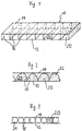
- Fig. 1 the sealing mat cut parallel to the longitudinal axis is shown in perspective, which is designated in its entirety by reference number 10.
- a first layer 12 which is arranged below, and a second, here above the first layer, essentially parallel to it, there are a plurality of side walls 16.
- These side walls 16 are essentially perpendicular to the layers 12, 14 and are at their upper and lower ends connected to the lower layer 12 and the upper layer 14, respectively.
- This connection can be made, for example, by needling or by means of an ecological glue.
- tubular chambers 22 are formed which are filled with sealing material 20. Because of its good swelling and thus sealing properties, bentonite is preferably used for this purpose, which is why bentonite is used as a sealing material in an exemplary but not restrictive manner.
- the side walls 16 run in the transverse direction of the sealing mat 10, i.e. so perpendicular to their longitudinal direction. They preferably have a distance of approximately 1.5 to 2.5 cm apart. This is advantageous in that the tubular chambers 22 located bentonite particles essentially only in the transverse direction the sealing mat 10, but not in the longitudinal direction. Because the side walls 16 have the aforementioned relatively small distance from one another, remains in the filled state the distance between the first layer 12 and the second layer 14 also largely constant. Consequently, the thickness of the sealing mat 10 and thus its tightness remains throughout Length practically constant. 1 is located with respect to the longitudinal direction the sealing mat 10 at the beginning and at the end of a side wall 16 which the sealing mat 10 completes in the longitudinal direction. As a result, the sealing mat also has the same at the ends Thickness up. However, the ends can also be formed so that the lower layer 12 and the protrude upper layer 14 over the last side wall 16 and connected together are.
- FIG. 2 differs from the first in that Side walls 17 are not perpendicular to the side walls 16 of the first embodiment lower layer 12 and the upper layer 14 are arranged, but that they chambers 23rd form with a U or V-shaped cross-section.
- the side walls 18 are tubular chambers 24 with an approximately round cross section.
- the chambers can also have other cross sections. It is important in any case that they prevent the unwanted displacement of the bentonite in the sealing mat.
- the side walls 16, 17 or 18 and the two layers 12, 14 are formed from paper.
- Paper as is known from the production of tea or coffee filters, has proven to be particularly suitable for the production of the second layer 14.
- a suitable grade has, for example, a basis weight of approximately 16.5 g / m 2 , a thickness of approximately 60 ⁇ m, a breaking strength in the dry state in the longitudinal and transverse directions of more than 13.0 N / 15 mm or more than 3, 2 N / 15 mm and a breaking force in the wet state in the transverse direction of more than 1.0 N / 15 mm and shows a sand loss of less than 75% with a particle size between 106 and 150 ⁇ m.
- papers for the production of serviettes or similar papers are also suitable for the second layer, provided they have specifications similar to those described above.
- the first layer 12 is made of less water-permeable paper, which is more stable than the paper second layer 14 is formed.
- paper has been found to be suitable for this purpose of bakery silk or napkins, which is more stable and waterproof than that for them second layer of paper that can be used, these papers each having a higher breaking strength, however, have less sand loss than the aforementioned papers.
- the aforementioned Papers for the formation of the first and second layers as well as the side walls come off Water exposure - albeit at different speeds - slowly and biologically be dismantled. Therefore, they can be used ecologically without hesitation.
- the sealing material used namely clay powder, such as bentonite, or other clay sealants are naturally occurring and environmentally friendly.
- the bentonites preferably used for the production of the sealing mat according to the invention are generally known.
- a typical example of this type of sealing material consists of: montmorillonite approx. 88% (smectite, bentonite), quartz (SiO 2 ) approx. 4%, calcite approx. 3%, illite approx. 3%, barite approx. 1% , Feldspar about 1%.
- montmorillonite approx. 88% smectite, bentonite
- quartz (SiO 2 ) approx. 4% calcite approx. 3%
- illite approx. 3% illite approx. 3%
- barite approx. 1% illite approx. 3%
- Feldspar about 1%.
- other materials with different compositions can be used to produce the sealing mat according to the invention.
- the sealing mat according to the invention is manufactured becomes.
- the sidewalls 16, 17 or 18 are attached to the first layer 12.
- the second layer 14 is attached to the side walls 16, 17 or 18.
- the sealing mat is on one end of the chambers closed, for example by the protruding first Layer 12 and second layer 14 are connected to one another on this end face.
- the Chambers are now filled with the sealing material, after which they are closed on this end face in a similar manner to the other end face become.
- the above fastening and connection operations can be both by gluing using an ecological glue as well as by needling with a suitable that is, biodegradable thread.
- the now finished sealing mat can then be rolled up become.
- the rolled up one Sealing mat for transport, storage and sale in a dust-proof film, preferably transparent film, packed.
- the sealing mat according to the invention can then be simply in place by unwinding be interpreted. In contrast to the application of the Sealing material alone also accepted unevenness, for example smaller stones become.
- Another advantage of this sealing mat compared to the needled mentioned above Sealing mats are that they are more supple due to the lower layer of paper is and adapts more easily to unevenness in the terrain, especially in the slope area Slipping prevented.
- the subsurface should in any case be well compacted in order to subsequent application of a load no more than necessary to discard and the tightness of the Affect layer.
- the spatial configuration of the sealing mat is not based on the exemplary embodiments specified above limited.
- the tubular chambers 22, 23 and 24 can pass through an additional, extending in the longitudinal direction of the sealing mat partition.
- these tubular chambers are already after the application of second layer only open at one end, over which they are sealed can be filled.
- Sealing material prevented even more from slipping.
- the chambers can also be in Longitudinal direction of the sealing mat instead of running in the transverse direction, which is why such a designed sealing mat can be laid out on longer slopes parallel to the slope and does not have to be installed perpendicular to it. Therefore it must - especially with not too high embankments - not so often cut and overlapped.
- the sealing mat according to the invention can also be used, for example, for green roofs and house wall drying or drying. It can also be advantageous the less water permeable first layer on top and the more water permeable Arrange layer below if access to water from below and not as in the previous ones Examples from above can be expected and the swelling process should begin below.
Abstract
Description
Die vorliegende Erfindung betrifft eine Dichtmatte zur Herstellung einer flüssigkeitsdichten Schicht im Erdreich gemäß dem Oberbegriff des Patentanspruchs 1.The present invention relates to a sealing mat for producing a liquid-tight Layer in the ground according to the preamble of claim 1.
Flüssigkeitsdichte Schichten zur Bildung einer Abdichtung im Erdreich werden in verschiedenen Bereichen eingesetzt, wie beispielsweise beim Deponiebau, bei der Anlage von Biotopen, Teich- und Wasseranlagen sowie beim Anschluß von Bauwerken im Wasserbereich. Insbesondere bei kleinen abzudichtenden Flächen, wie beispielsweise bei der Anlage kleiner Biotope, Teich- oder Wasseranlagen, weist jedoch jedes der bekannten Abdichtungsverfahren Nachteile auf.Liquid-tight layers to form a seal in the ground are used in different ways Areas used, such as in landfill construction, in the creation of biotopes, pond and Water systems and when connecting structures in the water area. Especially at small areas to be sealed, such as when creating small biotopes, pond or Water systems, however, each of the known sealing methods has disadvantages.
Der typische Schichtaufbau unter Einsatz derartiger flüssigkeitsdichter Schichten wird zunächst anhand der Anlage einer Deponie oder einer großen Wasseranlage erläutert. Nach dem Aushub des abzudichtenden Beckens werden dessen Boden und Böschungen verdichtet. Darauf wird quellfähiges, mineralisches Dichtungsmaterial aufgetragen. Hierfür eignen sich lehmartige Stoffe wie Tonmehle, Tondichtungsstoffe und dergleichen. Zu dieser Materialgruppe gehören auch die für diese Zwecke hervorragend geeigneten Bentonite, von denen verschiedene Arten mit unterschiedlichen Quell- und Wasseraufnahmeeigenschaften im Handel sind und auf die nachfolgend stellvertretend für die zu Dichtungszwecken einsetzbaren Tonmehle vorwiegend Bezug genommen wird. Die aufgebrachte Bentonitschicht - in der Regel etwa 1 bis 2 cm dick - wird mit einer mindestens 20 bis 30 cm dicken Abdeckschicht abgedeckt, um eine Auflast zu bilden, die dem Quelldruck entgegenwirkt, den der bei Wasserzufuhr aufquellende Bentonit erzeugt. Durch die Abdeckschicht wird außerdem eine Beschädigung oder ein Abtragen der Bentonitschicht aufgrund von Erosion verhindert. Bei dieser Art der Herstellung der Abdichtungsschicht darf der maximale Böschungswinkel an den Rändern nicht größer als etwa 20° sein, weil bei größerer Steilheit der Böschung die Gefahr des Abrutschens des Bentonits zu groß wäre und damit die Dichtigkeit nicht gewährleistet werden könnte. Ein derart niedriger zulässiger Böschungswinkel führt jedoch insbesondere bei kleinen Biotop- oder Teichanlagen dazu, daß ein unverhältnismäßig großer Anteil der Gesamtfläche auf den Rand- bzw. Böschungsbereich entfällt oder die Anlage aufgrund der begrenzten, zur Verfügung stehenden Fläche nicht mit der erwünschten Tiefe gebaut werden kann. Dies ist gerade bei kleineren Anlagen von Privatpersonen sehr nachteilig.The typical layer structure using such liquid-tight layers is first explained using the installation of a landfill or a large water system. After the excavation The bottom and embankments of the basin to be sealed are compacted. On it swellable, mineral sealing material applied. Clay-like substances are suitable for this such as clay flour, clay sealants and the like. This also includes the material group Bentonites, of which various types are extremely suitable for this purpose different swelling and water absorption properties are on the market and the following representative of the clay flours that can be used for sealing purposes, predominantly cover is taken. The applied bentonite layer - usually about 1 to 2 cm thick - is with a covering layer at least 20 to 30 cm thick to form a load that counteracts the swelling pressure generated by the swelling bentonite when water is supplied. By the cover layer will also damage or erode the bentonite layer prevented due to erosion. With this type of production of the sealing layer, the maximum angle of repose at the edges should not be greater than about 20 °, because at larger Steepness of the slope the risk of the bentonite slipping would be too great and thus the Tightness could not be guaranteed. Such a low slope angle However, especially in small biotope or pond systems, this leads to a disproportionate a large proportion of the total area is on the edge or embankment area or the system due to the limited available space not with the desired depth can be built. This is very disadvantageous, especially in the case of smaller systems by private individuals.
Es sind außerdem verschiedene Abdichtmatten bekannt, bei denen zwischen zwei vollflächig vernadelten Schichten aus Kunstfaser-Vliesstoff oder Glaswolle eine Bentonitschicht eingearbeitet ist. Derartige, zu einer Rolle aufwickelbare Matten sind zwar an steileren Böschungen einbaubar, jedoch ist die einarbeitbare Bentonitschicht relativ dünn, was entweder zu Dichtigkeitsproblemen führen kann oder den Einsatz von höchstwertigem, d.h. sehr stark quellfähigem, und damit sehr teurem Bentonit oder das Übereinanderlegen zweier Matten erfordert. Außerdem sind sich viele Personen, die naturnahe Teiche oder Biotope anlegen wollen, bewußt, daß der Einsatz von für derartige Matten verwendeten Kunststoffen ökologisch problematisch ist.Various sealing mats are also known, in which there is a full area between two needled layers of synthetic fiber nonwoven or glass wool incorporated a bentonite layer is. Such mats that can be rolled up into a roll can be installed on steeper slopes, however, the workable bentonite layer is relatively thin, which either leads to sealing problems can lead or the use of the highest quality, i.e. very swellable, and therefore very expensive bentonite or stacking two mats. In addition, there are many People who want to create near-natural ponds or biotopes are aware that the use of for plastics used such mats is ecologically problematic.
Ökologische Bedenken sprechen auch gegen den Einsen von Folien aus Kunststoff für die Abdichtung, die darüber hinaus den Nachteil aufweisen, daß sie am Stoß verschweißt werden müssen, um die Dichtigkeit zu gewährleisten. Ein derartiges Verschweißen ist zum einen zeitaufwendig, d.h. es erfordert einen zusätzlichen Arbeitsschritt, und es ist zum anderen für Privatpersonen mangels Erfahrung und geeigneter Gerätschaften oft schwer ausführbar.Ecological concerns also speak against the ones of plastic films for the Sealing, which also have the disadvantage that they are welded to the joint to ensure the tightness. Such welding is, on the one hand time consuming, i.e. it requires an extra step and it is for another Due to a lack of experience and suitable equipment, private individuals are often difficult to carry out.
In der Veröffentlichung von Saathoff/Ehrenberg mit dem Titel "Dichtung von der Rolle" im Heft 9/1992 von ",bd' baumaschinendienst" ist erwähnt, daß die Fertigung bentonitgefüllter Wellpappelemente zur Bauwerksdichtung bekannt war, ohne sich jedoch am Markt durchsetzen zu können. Derartige bentonitgefüllte Wellpappelemente, die alle Merkmale des Oberbegriffs des Patentanspruchs 1 aufweisen, sind für den vorgesehenen Einsatzzweck in der Praxis nicht anwendbar, da sie so steif sind, daß sie - anders als die vorgenannten Abdichtmatten - nicht zum Transport zu einer Rolle aufwickelbar sind, um am Einsatzort durch Abwickeln bzw. Abrollen ausgelegt zu werden. Außerdem können sie nur in relativ geringer Dicke hergestellt werden, was zu den gleichen Problemen führt, wie sie in Zusammenhang mit den vollflächig vernadelten Abdichtmatten beschrieben wurden.In the publication by Saathoff / Ehrenberg with the title "Poetry from a roll" in the booklet 9/1992 from ", bd 'baumaschinendienst" mentions that the production of bentonite-filled corrugated cardboard elements was known to seal the building, but without asserting itself on the market can. Such bentonite-filled corrugated cardboard elements that have all the features of the preamble of Have claim 1 are not for the intended purpose in practice applicable because they are so stiff that - unlike the above-mentioned sealing mats - not for Transport to a roll can be wound up to the site by unwinding or unrolling to be interpreted. In addition, they can only be made in a relatively small thickness, which leads to the same problems as in connection with the needled over the entire surface Sealing mats have been described.
Der vorliegenden Erfindung liegt die Aufgabe zugrunde, eine ökologische Dichtmatte zur Herstellung einer flüssigkeitsdichten Schicht im Erdreich zu schaffen, die kostengünstig hergestellt, einfach verlegt und auch für steile Böschungen verwendet werden kann.The present invention has for its object to provide an ecological sealing mat Creating a liquid-tight layer in the ground that is inexpensive to manufacture, easy to lay and can also be used for steep slopes.
Diese Aufgabe wird erfindungsgemäß mit einer Dichtmatte nach dem Patentanspruch 1 gelöst. Vorteilhafte Weiterbildungen der Erfindung sind Gegenstand der Unteransprüche.This object is achieved with a sealing mat according to claim 1. Advantageous developments of the invention are the subject of the dependent claims.
Da bei der erfindungsgemäßen Lösung die im wesentlichen parallel angeordneten wasserdurchlässigen Schichten sowie die Seitenwände aus Papier gebildet sind, ist die Dichtmatte sehr gut aufrollbar und kann dadurch leicht als Rolle transportiert sowie auf einfache Weise durch Abwickeln verlegt werden.Since in the solution according to the invention the substantially parallel water-permeable Layers as well as the side walls are made of paper, the sealing mat is very good can be rolled up and thus easily transported as a roll and in a simple manner Unwinding to be relocated.
Nachfolgend wird als typisches Beispiel der Fall betrachtet, daß Wasser von oben durch eine über einer Bentonitschicht befindliche Auflastschicht nach unten durchsickert. Bei Wasserzufuhr beginnt die Bentonitschicht zu quellen. Bei diesem Quellen werden Bentonitteilchen aufgrund des Quelldrucks in die Poren in der darüberliegenden Auflastschicht gepreßt, verschließen diese Poren und bilden somit eine Abdichtung gegen weitere Durchsickerung. Der Quellvorgang sollte aus Dichtigkeitsgründen nicht an irgend einer Stelle, die gerade feucht ist, sondern immer an derjenigen Seite der Dichtmatte beginnen, die der erwarteten Wasserzufuhr zugewandt ist (in diesem Beispiel die Oberseite). Im Teich- und Biotopbau wird die Dichtmatte daher so angeordnet, daß sich die wasserdurchlässigere zweite Schicht oben befindet und somit eine Deckschicht darstellt, während die weniger wasserdurchlässige erste Schicht sich als Trägerschicht unten befindet. Dies bietet den Vorteil, daß die Quellung der Bentonitschicht immer wie gewünscht von oben her beginnt, selbst wenn Wasser nicht nur von oben, sondern auch von unten an die Dichtmatte gelangt. Dies ist besonders in den ersten Tagen wichtig, bis sich die gesamte Anordnung aus der Bentonitschicht und der darüberliegenden Auflastschicht gut genug gesetzt hat.The following is considered as a typical example the case that water from above through a an overburden layer located below a bentonite layer. With water supply the bentonite layer begins to swell. In this swelling, bentonite particles are due to the Pressing swelling pressure into the pores in the overburden layer above closes these pores and thus form a seal against further leakage. The swelling process should be off Leak tightness not in any place that is currently damp, but always on start on the side of the sealing mat that faces the expected water supply (in the top in this example). In pond and biotope construction, the sealing mat is therefore arranged that the more water-permeable second layer is on top and thus a top layer represents, while the less water-permeable first layer as a support layer below located. This has the advantage that the swelling of the bentonite layer is always as desired starts at the top, even if water not only from above but also from below Sealing mat arrives. This is especially important in the first few days until the whole Arrangement of the bentonite layer and the overlying load layer set well enough Has.
Wenn sich nach circa vier bis acht Wochen die Seitenwände sowie die erste und die zweite Schicht, die jeweils aus Papier gebildet sind, aufgelöst haben, verbleibt im Boden nur noch die gequollene Schicht aus Bentonit, der ebenso wie alle übrigen Tonmehle ein natürlicher Stoff ist. Somit erfolgt durch den Einbau einer erfindungsgemäßen Dichtmatte kein Eintrag von künstlichen Substanzen in den Boden.If after about four to eight weeks the side walls and the first and second Layer, which are each made of paper, only remains in the ground swollen layer of bentonite, which, like all other clay flours, is a natural substance. Thus, by installing a sealing mat according to the invention there is no entry of artificial Substances in the soil.
Die höhere Wasserdurchlässigkeit der zweiten Schicht im Vergleich zur ersten Schicht kann dadurch erreicht werden, daß das Papier der zweiten Schicht poröser als das Papier der ersten Schicht ist, d.h. daß es größere oder mehr Poren aufweist als dasjenige der ersten Schicht.The higher water permeability of the second layer compared to the first layer can can be achieved in that the paper of the second layer is more porous than the paper of the first Layer, i.e. that it has larger or more pores than that of the first layer.
Für die Stabilität der Abdichtungsschicht in den ersten Monaten nach dem Einbau ist es von Vorteil, wenn sich die zweite, in der Regel oben liegende Schicht bei Wassereinwirkung schneller auflöst als die erste, gewöhnlich unten liegende Schicht. Dies verstärkt nach dem Beginn der Auflösung des Papiers die Tatsache, daß der Wasserzutritt von oben leichter möglich ist als von unten. Ferner wird dadurch sichergestellt, daß Bentonitteilchen von der Unterseite der Bentonitschicht nicht zu frühzeitig aufgrund des Quellvorgangs nach unten wandern können.For the stability of the sealing layer in the first months after installation, it is of Advantage if the second layer, which is usually on top, is exposed to water more quickly dissolves as the first, usually bottom layer. This intensifies after the start of Dissolution of the paper the fact that it is easier to access water from above than from below. It also ensures that bentonite particles from the underside of the bentonite layer cannot migrate down too early due to the swelling process.
Die Seitenwände können beispielsweise so ausgebildet sein, daß sie ohne Einbeziehung der ersten und der zweiten Schicht schlauchartige Kammern bilden, die nur an den Stirnseiten offen sind. In diesem Fall ist es vorteilhaft, wenn diese Seitenwände aus demselben Papier wie die obere, zweite Schicht gebildet sind, nämlich aus einem wasserdurchlässigeren Papier als dasjenige der unteren, ersten Schicht. Dann kann bei Wassereinwirkung von oben, beispielsweise in einem Gartenteich oder Biotop, das Wasser auch die Seitenwände leicht durchdringen und dadurch die Bentonitteilchen zur Quellung bringen.The side walls can be designed, for example, so that they do not involve the form first and second layers of tubular chambers that are only open at the end faces are. In this case it is advantageous if these side walls are made of the same paper as that upper, second layer are formed, namely from a more water-permeable paper than that of the lower, first layer. Then when exposed to water from above, for example in a garden pond or biotope, the water also easily penetrate the side walls and this causes the bentonite particles to swell.
Wenn für die Dichtmatte als Dichtungsmaterial aus den vielen verschiedenen Materialien solcher Bentonit ausgewählt wird, der ein Wasseraufnahmevermögen zwischen 200 und 800 % aufweist, und wenn dieser Bentonit mit einem Flächengewicht zwischen 8 und 15 kg/m2 in der Dichtmatte angeordnet ist, genügt eine einzige Dichtmatte zur Abdichtung gegen Flüssigkeitsdurchsickerung. Wenn statt dessen andere Dichtungsmaterialien mit niedrigerem Wasseraufnahmevermögen und/oder einer niedrigeren Massendichte pro Fläche, d.h. einem niedrigeren Flächengewicht, verwendet werden, müssen zum Erzielen einer dichten Schicht zwei oder mehr Dichtmatten übereinander angeordnet werden. Dies erhöht dann natürlich die Anzahl der für das Erzielen einer Abdichtung erforderlichen Arbeitsschritte, ist jedoch prinzipiell möglich. Wenn dagegen Bentonit mit einem Wasseraufnahmevermögen zwischen 350 und 600 % verwendet wird, von dem soviel in der Dichtmatte angeordnet ist, daß dessen Flächengewicht zwischen 10 und 12 kg/m2 beträgt, ist die dadurch erhaltene Dichtmatte zum einen relativ preisgünstig, weil nicht der quellfähigste und damit teuerste Bentonit verwendet werden muß. Zum anderen erfordert das für eine sichere Abdichtung erforderliche Flächengewicht keine zu hohe Gesamtmasse an Bentonit, die den Transport und das Verlegen unnötig erschweren würde. If the sealing mat selected from the many different materials for the sealing mat is such a bentonite which has a water absorption capacity of between 200 and 800%, and if this bentonite is arranged in the sealing mat with a basis weight of between 8 and 15 kg / m 2 , only one is sufficient Sealing mat for sealing against liquid leakage. If instead other sealing materials with a lower water absorption capacity and / or a lower mass density per area, ie a lower basis weight, are used, two or more sealing mats must be arranged one above the other in order to achieve a tight layer. Of course, this then increases the number of work steps required to achieve a seal, but is in principle possible. If, on the other hand, bentonite with a water absorption capacity of between 350 and 600% is used, of which so much is arranged in the sealing mat that its basis weight is between 10 and 12 kg / m 2 , the sealing mat obtained in this way is relatively inexpensive on the one hand because it is not the most swellable and therefore the most expensive bentonite must be used. On the other hand, the weight per unit area required for a secure seal does not require the overall mass of bentonite being too high, which would unnecessarily complicate transport and laying.
Weitere Vorteile, Merkmale und Besonderheiten der Erfindung ergeben sich aus der nachfolgenden Beschreibung eines bevorzugten, jedoch nicht beschränkenden Ausführungsbeispiels der Erfindung anhand der schematischen und nicht maßstabsgetreuen Zeichnungen. Es zeigen:
- Fig. 1
- eine perspektivische Darstellung einer in Längsrichtung aufgeschnittenen ersten Ausführungsform der erfindungsgemäßen Dichtmatte,
- Fig. 2
- einen Längsschnitt durch einen Teil einer zweiten Ausführungsform der erfindungsgemäßen Dichtmatte, und
- Fig. 3
- einen Längsschnitt durch einen Teil einer dritten Ausführungsform der erfindungsgemäßen Dichtmatte.
- Fig. 1
- 2 shows a perspective illustration of a first embodiment of the sealing mat according to the invention, cut open in the longitudinal direction,
- Fig. 2
- a longitudinal section through part of a second embodiment of the sealing mat according to the invention, and
- Fig. 3
- a longitudinal section through part of a third embodiment of the sealing mat according to the invention.
In Fig. 1 ist die parallel zur Längsachse aufgeschnittene Dichtmatte perspektivisch gezeigt, die in
ihrer Gesamtheit mit der Bezugszahl 10 bezeichnet ist. Zwischen einer ersten, hier unten
angeordneten Schicht 12 und einer zweiten, hier oberhalb der ersten Schicht im wesentlichen
parallel zu ihr angeordneten zweiten Schicht 14 befinden sich mehrere Seitenwände 16. Diese
Seitenwände 16 stehen im wesentlichen senkrecht zu den Schichten 12, 14 und sind an ihrem
oberen und unteren Ende jeweils mit der unteren Schicht 12 bzw. der oberen Schicht 14
verbunden. Diese Verbindung kann beispielsweise durch eine Vernadelung oder mittels eines
Ökoleims erfolgen. Dadurch werden schlauchartige Kammern 22 gebildet, die mit Dichtungsmaterial
20 befüllt werden. Wegen seiner guten Quell- und damit Abdichteigenschaften wird hierfür
vorzugsweise Bentonit verwendet, weshalb im folgenden in exemplarischer, jedoch nicht
beschränkender Weise von Bentonit als Dichtungsmaterial ausgegangen wird. In einer typischen
Konfektionierung ist eine derartige Dichtmatte 3 m lang und 1,25 m breit. Wenn soviel Bentonit
verwendet wird, daß es in der Dichtmatte mit einem Flächengewicht von 10 kg/m2 enthalten ist,
entspricht dies einer Höhe der Dichtmatte von etwa 1 cm. Da die untere Schicht 12, die obere
Schicht 14 und die Seitenwände 16 aus Papier gebildet sind, läßt sich die Dichtmatte 10 leicht
aufrollen. Wenn die vorstehend genannten Abmessungen verwendet werden und die Dichtmatte
mit dem genannten Bentonit gefüllt ist, weist sie eine Masse von ca. 35 kg (entsprechend einem
Gewicht von etwa 350 N) auf. Damit kann eine Dichtmatte in aufgerolltem Zustand von einer
Person getragen und an Ort und Stelle zum Einbau leicht abgewickelt werden.In Fig. 1, the sealing mat cut parallel to the longitudinal axis is shown in perspective, which is designated in its entirety by
Gemäß Darstellung in Fig. 1 verlaufen die Seitenwände 16 in Querrichtung der Dichtmatte 10,
d.h. also senkrecht zu deren Längsrichtung. Sie weisen vorzugsweise einen Abstand von etwa
1,5 bis 2,5 cm voneinander auf. Dies ist insofern vorteilhaft, als sich dadurch die in den
schlauchartigen Kammern 22 befindlichen Bentonitteilchen im wesentlichen nur in Querrichtung
der Dichtmatte 10, nicht jedoch in deren Längsrichtung verschieben können. Da die Seitenwände
16 den genannten relativ kleinen Abstand voneinander aufweisen, bleibt im gefüllten Zustand
auch der Abstand zwischen der ersten Schicht 12 und der zweiten Schicht 14 weitgehend
konstant. Folglich bleibt die Dicke der Dichtmatte 10 und damit ihre Dichtigkeit über die gesamte
Länge praktisch konstant. In der Darstellung gemäß Fig. 1 befindet sich bezüglich der Längsrichtung
der Dichtmatte 10 jeweils am Anfang und am Ende eine Seitenwand 16, die die Dichtmatte
10 in Längsrichtung abschließt. Dadurch weist die Dichtmatte auch an den Enden die gleiche
Dicke auf. Die Enden können jedoch auch so gebildet werden, daß die untere Schicht 12 und die
obere Schicht 14 über die jeweils letzte Seitenwand 16 überstehen und miteinander verbunden
sind.As shown in FIG. 1, the side walls 16 run in the transverse direction of the sealing
Die in Fig. 2 dargestellte Ausführungsform unterscheidet sich von der ersten insofern, als die
Seitenwände 17 nicht wie die Seitenwände 16 der ersten Ausführungsform senkrecht zur
unteren Schicht 12 und zur oberen Schicht 14 angeordnet sind, sondern daß sie Kammern 23
mit U- oder V-förmigem Querschnitt bilden. Bei der dritten Ausführungsform gemäß Fig. 3 bilden
die Seitenwände 18 schlauchförmige Kammern 24 mit in etwa rundem Querschnitt. Selbstverständlich
können die Kammern auch andere Querschnitte aufweisen. Wichtig ist in jedem Fall,
daß sie die unerwünschte Verlagerung des Bentonits in der Dichtmatte verhindern.The embodiment shown in Fig. 2 differs from the first in that
Wie vorstehend ausgeführt, sind die Seitenwände 16, 17 oder 18 sowie die zwei Schichten 12,
14 aus Papier gebildet. Als besonders geeignet für die Herstellung der zweiten Schicht 14 hat
sich Papier erwiesen, wie es aus der Herstellung von Tee- oder Kaffeefiltern bekannt ist. Eine
geeignete Sorte weist beispielsweise ein Flächengewicht von etwa 16,5 g/m2, eine Dicke von
etwa 60 µm, eine Bruchkraft in trockenem Zustand in Längs- und Querrichtung von mehr als
13,0 N/15 mm bzw. mehr als 3,2 N/15 mm sowie eine Bruchkraft in nassem Zustand in
Querrichtung von mehr als 1,0 N/15 mm auf und zeigt bei einer Partikelgröße zwischen 106 und
150 µm einen Sandausfall von weniger als 75 %. Für die zweite Schicht sind jedoch u. a. auch
Papiere zur Herstellung von Servietten oder ähnliche Papiere geeignet, sofern sie ähnliche
Spezifikationen wie die oben beschriebenen aufweisen.As stated above, the
Die erste Schicht 12 ist aus weniger wasserdurchlässigem Papier, das stabiler als das Papier der
zweiten Schicht 14 ist, gebildet. Als hierfür geeignet hat sich beispielsweise Papier zur Herstellung
von Bäckerseide oder Servietten, das stabiler und wasserundurchlässiger ist als das für die
zweite Schicht einsetzbare Papier, erwiesen, wobei diese Papiere jeweils eine höhere Bruchkraft,
jedoch einen geringeren Sandausfall als die vorgenannten Papiere aufweisen. Die vorgenannten
Papiere für die Bildung der ersten und zweiten Schicht sowie der Seitenwände lösen sich unter
Wassereinwirkung - wenn auch unterschiedlich schnell - langsam auf und können biologisch
abgebaut werden. Daher sind sie ökologisch bedenkenfrei verwendbar.The
Auch das verwendete Dichtungsmaterial, nämlich Tonmehl, wie beispielsweise Bentonit, oder andere Tondichtungsstoffe sind in der Natur vorkommende Stoffe und umweltverträglich. Die für die Herstellung der erfindungsgemäßen Dichtmatte vorzugsweise verwendeten Bentonite sind allgemein bekannt. Ein typisches Beispiel dieser Art von Dichtungsmaterial setzt sich zusammen aus: Montmorillonit ca. 88 % (Smektit, Bentonit), Quarz (SiO2) ca. 4 %, Calcit ca. 3 %, Illit ca. 3 %, Baryt ca. 1 %, Feldspat ca. 1 %. Selbstverständlich können je nach Anforderung andere Materialien mit anderen Zusammensetzungen zur Herstellung der erfindungsgemäßen Dichtmatte verwendet werden. The sealing material used, namely clay powder, such as bentonite, or other clay sealants are naturally occurring and environmentally friendly. The bentonites preferably used for the production of the sealing mat according to the invention are generally known. A typical example of this type of sealing material consists of: montmorillonite approx. 88% (smectite, bentonite), quartz (SiO 2 ) approx. 4%, calcite approx. 3%, illite approx. 3%, barite approx. 1% , Feldspar about 1%. Of course, depending on requirements, other materials with different compositions can be used to produce the sealing mat according to the invention.
Nachstehend soll kurz beschrieben werden, wie die erfindungsgemäße Dichtmatte hergestellt
wird. Zuerst werden die Seitenwände 16, 17 oder 18 an der ersten Schicht 12 befestigt. Dann
wird die zweite Schicht 14 an den Seitenwänden 16, 17 oder 18 befestigt. Dadurch entstehen
an beiden Stirnseiten offene schlauchartige Kammern 22, 23 oder 24, mit unterschiedlichen
Querschnitten je nach Ausgestaltung der Seitenwände. Anschließend wird die Dichtmatte an
einer Stirnseite der Kammern verschlossen, beispielsweise indem die überstehende erste
Schicht 12 und zweite Schicht 14 an dieser Stirnseite miteinander verbunden werden. Durch die
Öffnung an der anderen Stirnseite werden die Kammern nun mit dem Dichtungsmaterial befüllt,
wonach sie auch an dieser Stirnseite in ähnlicher Weise wie bei der anderen Stirnseite verschlossen
werden. Die vorstehend genannten Befestigungs- und Verbindungsvorgänge können sowohl
durch Verkleben unter Einsatz eines Ökoleims als auch durch Vernadeln mit einem geeigneten,
also ökologisch abbaubaren Faden, erfolgen. Die nunmehr fertige Dichtmatte kann dann aufgerollt
werden. Um ein Ausstauben des Dichtungsmaterials zu verhindern, wird die aufgerollte
Dichtmatte zum Transport, zur Lagerung und zum Verkauf in eine staubundurchlässige Folie,
vorzugsweise Klarsichtfolie, verpackt.The following is a brief description of how the sealing mat according to the invention is manufactured
becomes. First, the
Die erfindungsgemäße Dichtmatte kann dann an Ort und Stelle durch einfaches Abwickeln ausgelegt werden. Dabei können im Gegensatz zum eingangs beschriebenen Auftragen des Dichtungsmaterials alleine auch Unebenheiten, beispielsweise kleinere Steine, in Kauf genommen werden. Ein weiterer Vorteil dieser Dichtmatte gegenüber den eingangs erwähnten vernadelten Abdichtmatten besteht darin, daß sie aufgrund der unteren Schicht aus Papier anschmiegsamer ist und sich leichter an Unebenheiten im Gelände anpaßt, was insbesondere im Hangbereich ein Abgleiten verhindert. Außerdem ist nicht wie beim Auftragen des Dichtungsmaterials alleine eine gut verbindende Schicht unmittelbar über dem Dichtungsmaterial erforderlich, d.h. diese muß nicht lehmhaltig sein. Der Untergrund sollte jedoch in jedem Fall gut verdichtet sein, um sich bei späterem Aufbringen einer Auflast nicht mehr als notwendig zu verwerfen und die Dichtigkeit der Schicht zu beeinträchtigen. Um diese Dichtigkeit zu gewährleisten, ist es im übrigen erforderlich, benachbarte Dichtmatten etwa 2 bis 3 cm überlappen zu lassen. Aus diesem Grund ist es anzuraten, eine 20 cm dicke Auflastschicht auf der Dichtmatte anzuordnen, so daß auch auf den Überlappungsstellen eine Auflast vorhanden ist, die stark genug ist, um dem entstehenden Quelldruck des Dichtungsmaterials entgegenzuwirken. (Für die nicht überlappenden Bereiche der Dichtmatte würde eine ca. 10 cm dicke Auflastschicht ausreichen.)The sealing mat according to the invention can then be simply in place by unwinding be interpreted. In contrast to the application of the Sealing material alone also accepted unevenness, for example smaller stones become. Another advantage of this sealing mat compared to the needled mentioned above Sealing mats are that they are more supple due to the lower layer of paper is and adapts more easily to unevenness in the terrain, especially in the slope area Slipping prevented. In addition, one is not the same as when applying the sealing material well-connecting layer required immediately above the sealing material, i.e. this must not be clayey. However, the subsurface should in any case be well compacted in order to subsequent application of a load no more than necessary to discard and the tightness of the Affect layer. To ensure this tightness, it is also necessary to allow adjacent sealing mats to overlap by about 2 to 3 cm. Because of this, it is advisable to arrange a 20 cm thick load layer on the sealing mat, so that also on the Overlap there is a ballast that is strong enough to withstand the arising Counteract swelling pressure of the sealing material. (For the non-overlapping areas of the Sealing mat an approx. 10 cm thick load layer would be sufficient.)
Die räumliche Ausgestaltung der Dichtmatte ist nicht auf die oben angegebenen Ausführungsbeispiele
beschränkt. So können beispielsweise die schlauchartigen Kammern 22, 23 und 24 durch
eine zusätzliche, in Längsrichtung der Dichtmatte verlaufende Zwischenwand unterteilt sein. Bei
dieser Anordnung sind dann diese schlauchartigen Kammern bereits nach dem Aufbringen der
zweiten Schicht jeweils nur noch an einer Stirnseite offen, über die sie mit Dichtungsmaterial
befüllt werden können. Durch eine derartige Zwischenwand wird das in den Kammern befindliche
Dichtungsmaterial noch stärker am Verrutschen gehindert. Die Kammern können jedoch auch in
Längsrichtung der Dichtmatte statt in deren Querrichtung verlaufen, weshalb eine derartig
ausgestaltete Dichtmatte in längeren Hangbereichen parallel zum Hang ausgelegt werden kann
und nicht senkrecht dazu verlegt werden muß. Daher muß sie - insbesondere bei nicht allzu
hohen Böschungen - nicht so oft abgetrennt und überlappt werden. The spatial configuration of the sealing mat is not based on the exemplary embodiments specified above
limited. For example, the
Neben den genannten Einsatzmöglichkeiten beim Biotop-, Teich-, Garten- und Landschaftsbau kann die erfindungsgemäße Dichtmatte außerdem beispielsweise auch bei der Dachbegrünung und der Hausmauertrocknung bzw. -trockenhaltung verwendet werden. Ferner kann es vorteilhaft sein, die weniger wasserdurchlässige erste Schicht oben und die stärker wasserdurchlässige Schicht unten anzuordnen, wenn der Wasserzutritt von unten und nicht wie bei den vorstehenden Beispielen von oben zu erwarten ist und der Quellvorgang unten beginnen soll.In addition to the mentioned uses in biotope, pond, garden and landscape construction the sealing mat according to the invention can also be used, for example, for green roofs and house wall drying or drying. It can also be advantageous the less water permeable first layer on top and the more water permeable Arrange layer below if access to water from below and not as in the previous ones Examples from above can be expected and the swelling process should begin below.
Claims (5)
dadurch gekennzeichnet, daß die Schichten (12, 14) sowie die Seitenwände (16; 17; 18) aus Papier gebildet sind und
characterized in that the layers (12, 14) and the side walls (16; 17; 18) are formed from paper and
Applications Claiming Priority (2)
| Application Number | Priority Date | Filing Date | Title |
|---|---|---|---|
| DE19827909A DE19827909A1 (en) | 1998-06-23 | 1998-06-23 | Sealing mat for creating a liquid-tight layer in the ground |
| DE19827909 | 1998-06-23 |
Publications (2)
| Publication Number | Publication Date |
|---|---|
| EP0967334A1 true EP0967334A1 (en) | 1999-12-29 |
| EP0967334B1 EP0967334B1 (en) | 2003-08-13 |
Family
ID=7871731
Family Applications (1)
| Application Number | Title | Priority Date | Filing Date |
|---|---|---|---|
| EP99111720A Expired - Lifetime EP0967334B1 (en) | 1998-06-23 | 1999-06-17 | Sealing mat for the building of a fluid-impervious layer in the soil |
Country Status (3)
| Country | Link |
|---|---|
| EP (1) | EP0967334B1 (en) |
| AT (1) | ATE247196T1 (en) |
| DE (2) | DE19827909A1 (en) |
Cited By (1)
| Publication number | Priority date | Publication date | Assignee | Title |
|---|---|---|---|---|
| EP1416094A1 (en) * | 2002-10-10 | 2004-05-06 | Cidieffe S.r.l. | A multilayer sealing mat |
Citations (3)
| Publication number | Priority date | Publication date | Assignee | Title |
|---|---|---|---|---|
| US4467015A (en) * | 1981-11-02 | 1984-08-21 | Clem Arthur G | Waterproofing structure |
| US4565468A (en) * | 1983-10-24 | 1986-01-21 | Crawford Leslie A | Moisture impervient barrier and method for making same |
| EP0442597A1 (en) * | 1990-02-15 | 1991-08-21 | American Colloid Company | Moisture-impervious panel capable of rapid/delayed hydration |
Family Cites Families (4)
| Publication number | Priority date | Publication date | Assignee | Title |
|---|---|---|---|---|
| EP0362193B1 (en) * | 1988-09-28 | 1992-12-02 | Girmes Gmbh | Process for sealing against the penetration of liquids and/or gases |
| DE4012301C2 (en) * | 1990-04-18 | 1999-03-25 | Huesker Synthetic Gmbh & Co | Formwork cover |
| DE4203861A1 (en) * | 1992-02-11 | 1993-08-12 | Naue Fasertechnik | WATER AND / OR OIL-RESISTANT SEALING MAT made of SOAKABLE CLAY |
| DK0563453T3 (en) * | 1992-04-02 | 1996-01-15 | Naue Fasertechnik | Process for producing a water and / or oil impermeable swellable clay-containing sealing mat |
-
1998
- 1998-06-23 DE DE19827909A patent/DE19827909A1/en not_active Withdrawn
-
1999
- 1999-06-17 AT AT99111720T patent/ATE247196T1/en not_active IP Right Cessation
- 1999-06-17 EP EP99111720A patent/EP0967334B1/en not_active Expired - Lifetime
- 1999-06-17 DE DE59906564T patent/DE59906564D1/en not_active Expired - Lifetime
Patent Citations (3)
| Publication number | Priority date | Publication date | Assignee | Title |
|---|---|---|---|---|
| US4467015A (en) * | 1981-11-02 | 1984-08-21 | Clem Arthur G | Waterproofing structure |
| US4565468A (en) * | 1983-10-24 | 1986-01-21 | Crawford Leslie A | Moisture impervient barrier and method for making same |
| EP0442597A1 (en) * | 1990-02-15 | 1991-08-21 | American Colloid Company | Moisture-impervious panel capable of rapid/delayed hydration |
Cited By (1)
| Publication number | Priority date | Publication date | Assignee | Title |
|---|---|---|---|---|
| EP1416094A1 (en) * | 2002-10-10 | 2004-05-06 | Cidieffe S.r.l. | A multilayer sealing mat |
Also Published As
| Publication number | Publication date |
|---|---|
| EP0967334B1 (en) | 2003-08-13 |
| ATE247196T1 (en) | 2003-08-15 |
| DE19827909A1 (en) | 1999-12-30 |
| DE59906564D1 (en) | 2003-09-18 |
Similar Documents
| Publication | Publication Date | Title |
|---|---|---|
| DE2633752A1 (en) | EARTH DRAINAGE DEVICE | |
| DE2327618A1 (en) | LARGE-AREA MULTI-LAYER DRAIN ELEMENT | |
| DE8111266U1 (en) | INSULATING ELEMENT | |
| DE2657964A1 (en) | WATERPROOF FLOOR OR WALL COVERING IN PARTICULAR FOR TERRACES, CONTAINERS AND THE like AND PROCESS FOR ITS MANUFACTURING | |
| DE202016102923U1 (en) | Planting area construction | |
| WO2009146901A1 (en) | Stationary layered floodwater protection | |
| EP0967334B1 (en) | Sealing mat for the building of a fluid-impervious layer in the soil | |
| DE19716516A1 (en) | Insulating drainage elements made of rigid plastic foam and process for use in the ground | |
| DE2415023B2 (en) | Noise barrier | |
| EP0437171A1 (en) | Method for forming a vegetation supporting layer with such a system and use of such a system | |
| DE69815344T2 (en) | SEALING ARTICLES FOR USE ON BUILDINGS | |
| DE4012301C2 (en) | Formwork cover | |
| DE2321647A1 (en) | PROCESS AND FINISHED PART FOR THE PRODUCTION OF A CORE OR SURFACE SEAL | |
| DE19649628A1 (en) | Mineral seal construction, manufacturing processes and geosynthetic sealing strip | |
| DE2102763C3 (en) | Filter layer, especially for a drainage pipe | |
| DE3312402A1 (en) | Vegetative roof covering | |
| DE2433975A1 (en) | RAIL MATERIAL FOR DRAINAGE PURPOSES | |
| DE60203517T2 (en) | Multi-layered sealing mat | |
| CH678739A5 (en) | Bank-covering method for plant growth - comprises flat textile with cover impervious to material sprayed on | |
| DE2515362C3 (en) | Retaining wall made of building elements | |
| DE19808019A1 (en) | Sealing layer for sealing ground surfaces, road surfaces and top and bottom surfaces of dumps | |
| DE102009016326A1 (en) | Composite mat, useful in garden ponds as a pond sealing material, comprises a foil-like carrier and a volume material arranged on it, where the foil-like carrier is waterproof | |
| DE4109050C2 (en) | Barrier drainage mat | |
| DE4329957A1 (en) | Drainage mat made of natural fibres - includes nonwoven consisting of wood fibres that are stuck together | |
| AT369469B (en) | DRAINAGE ELEMENT |
Legal Events
| Date | Code | Title | Description |
|---|---|---|---|
| PUAI | Public reference made under article 153(3) epc to a published international application that has entered the european phase |
Free format text: ORIGINAL CODE: 0009012 |
|
| AK | Designated contracting states |
Kind code of ref document: A1 Designated state(s): AT BE CH DE ES FR GB IT LI |
|
| AX | Request for extension of the european patent |
Free format text: AL;LT;LV;MK;RO;SI |
|
| 17P | Request for examination filed |
Effective date: 20000629 |
|
| AKX | Designation fees paid |
Free format text: AT BE CH DE ES FR GB IT LI |
|
| 17Q | First examination report despatched |
Effective date: 20010222 |
|
| GRAH | Despatch of communication of intention to grant a patent |
Free format text: ORIGINAL CODE: EPIDOS IGRA |
|
| GRAH | Despatch of communication of intention to grant a patent |
Free format text: ORIGINAL CODE: EPIDOS IGRA |
|
| GRAA | (expected) grant |
Free format text: ORIGINAL CODE: 0009210 |
|
| AK | Designated contracting states |
Designated state(s): AT BE CH DE ES FR GB IT LI |
|
| PG25 | Lapsed in a contracting state [announced via postgrant information from national office to epo] |
Ref country code: IT Free format text: LAPSE BECAUSE OF FAILURE TO SUBMIT A TRANSLATION OF THE DESCRIPTION OR TO PAY THE FEE WITHIN THE PRE;WARNING: LAPSES OF ITALIAN PATENTS WITH EFFECTIVE DATE BEFORE 2007 MAY HAVE OCCURRED AT ANY TIME BEFORE 2007. THE CORRECT EFFECTIVE DATE MAY BE DIFFERENT FROM THE ONE RECORDED.SCRIBED TIME-LIMIT Effective date: 20030813 Ref country code: GB Free format text: LAPSE BECAUSE OF FAILURE TO SUBMIT A TRANSLATION OF THE DESCRIPTION OR TO PAY THE FEE WITHIN THE PRESCRIBED TIME-LIMIT Effective date: 20030813 Ref country code: FR Free format text: LAPSE BECAUSE OF NON-PAYMENT OF DUE FEES Effective date: 20030813 Ref country code: ES Free format text: LAPSE BECAUSE OF FAILURE TO SUBMIT A TRANSLATION OF THE DESCRIPTION OR TO PAY THE FEE WITHIN THE PRESCRIBED TIME-LIMIT Effective date: 20030813 |
|
| REG | Reference to a national code |
Ref country code: GB Ref legal event code: FG4D Free format text: NOT ENGLISH |
|
| REG | Reference to a national code |
Ref country code: CH Ref legal event code: EP |
|
| REF | Corresponds to: |
Ref document number: 59906564 Country of ref document: DE Date of ref document: 20030918 Kind code of ref document: P |
|
| GBV | Gb: ep patent (uk) treated as always having been void in accordance with gb section 77(7)/1977 [no translation filed] |
Effective date: 20030813 |
|
| PG25 | Lapsed in a contracting state [announced via postgrant information from national office to epo] |
Ref country code: AT Free format text: LAPSE BECAUSE OF NON-PAYMENT OF DUE FEES Effective date: 20040617 |
|
| PLBE | No opposition filed within time limit |
Free format text: ORIGINAL CODE: 0009261 |
|
| STAA | Information on the status of an ep patent application or granted ep patent |
Free format text: STATUS: NO OPPOSITION FILED WITHIN TIME LIMIT |
|
| PG25 | Lapsed in a contracting state [announced via postgrant information from national office to epo] |
Ref country code: LI Free format text: LAPSE BECAUSE OF NON-PAYMENT OF DUE FEES Effective date: 20040630 Ref country code: CH Free format text: LAPSE BECAUSE OF NON-PAYMENT OF DUE FEES Effective date: 20040630 Ref country code: BE Free format text: LAPSE BECAUSE OF NON-PAYMENT OF DUE FEES Effective date: 20040630 |
|
| 26N | No opposition filed |
Effective date: 20040514 |
|
| EN | Fr: translation not filed | ||
| BERE | Be: lapsed |
Owner name: *ZAUSER HANS Effective date: 20040630 |
|
| REG | Reference to a national code |
Ref country code: CH Ref legal event code: PL |
|
| PGFP | Annual fee paid to national office [announced via postgrant information from national office to epo] |
Ref country code: DE Payment date: 20140630 Year of fee payment: 16 |
|
| REG | Reference to a national code |
Ref country code: DE Ref legal event code: R119 Ref document number: 59906564 Country of ref document: DE |
|
| REG | Reference to a national code |
Ref country code: DE Ref legal event code: R119 Ref document number: 59906564 Country of ref document: DE Effective date: 20150101 |
|
| PG25 | Lapsed in a contracting state [announced via postgrant information from national office to epo] |
Ref country code: DE Free format text: LAPSE BECAUSE OF NON-PAYMENT OF DUE FEES Effective date: 20150101 |