EP0966909A2 - Food processor with a mixing vessel and a drive mechanism for an agitator in the mixing vessel - Google Patents
Food processor with a mixing vessel and a drive mechanism for an agitator in the mixing vessel Download PDFInfo
- Publication number
- EP0966909A2 EP0966909A2 EP99118360A EP99118360A EP0966909A2 EP 0966909 A2 EP0966909 A2 EP 0966909A2 EP 99118360 A EP99118360 A EP 99118360A EP 99118360 A EP99118360 A EP 99118360A EP 0966909 A2 EP0966909 A2 EP 0966909A2
- Authority
- EP
- European Patent Office
- Prior art keywords
- food processor
- mixing vessel
- agitator
- heating
- speed
- Prior art date
- Legal status (The legal status is an assumption and is not a legal conclusion. Google has not performed a legal analysis and makes no representation as to the accuracy of the status listed.)
- Granted
Links
Images

Classifications
-
- A—HUMAN NECESSITIES
- A47—FURNITURE; DOMESTIC ARTICLES OR APPLIANCES; COFFEE MILLS; SPICE MILLS; SUCTION CLEANERS IN GENERAL
- A47J—KITCHEN EQUIPMENT; COFFEE MILLS; SPICE MILLS; APPARATUS FOR MAKING BEVERAGES
- A47J36/00—Parts, details or accessories of cooking-vessels
- A47J36/16—Inserts
-
- A—HUMAN NECESSITIES
- A47—FURNITURE; DOMESTIC ARTICLES OR APPLIANCES; COFFEE MILLS; SPICE MILLS; SUCTION CLEANERS IN GENERAL
- A47J—KITCHEN EQUIPMENT; COFFEE MILLS; SPICE MILLS; APPARATUS FOR MAKING BEVERAGES
- A47J27/00—Cooking-vessels
- A47J27/004—Cooking-vessels with integral electrical heating means
-
- A—HUMAN NECESSITIES
- A47—FURNITURE; DOMESTIC ARTICLES OR APPLIANCES; COFFEE MILLS; SPICE MILLS; SUCTION CLEANERS IN GENERAL
- A47J—KITCHEN EQUIPMENT; COFFEE MILLS; SPICE MILLS; APPARATUS FOR MAKING BEVERAGES
- A47J27/00—Cooking-vessels
- A47J27/14—Cooking-vessels for use in hotels, restaurants, or canteens
-
- A—HUMAN NECESSITIES
- A47—FURNITURE; DOMESTIC ARTICLES OR APPLIANCES; COFFEE MILLS; SPICE MILLS; SUCTION CLEANERS IN GENERAL
- A47J—KITCHEN EQUIPMENT; COFFEE MILLS; SPICE MILLS; APPARATUS FOR MAKING BEVERAGES
- A47J36/00—Parts, details or accessories of cooking-vessels
- A47J36/16—Inserts
- A47J36/165—Stirring devices operatively connected to cooking vessels when being removably inserted inside
-
- A—HUMAN NECESSITIES
- A47—FURNITURE; DOMESTIC ARTICLES OR APPLIANCES; COFFEE MILLS; SPICE MILLS; SUCTION CLEANERS IN GENERAL
- A47J—KITCHEN EQUIPMENT; COFFEE MILLS; SPICE MILLS; APPARATUS FOR MAKING BEVERAGES
- A47J36/00—Parts, details or accessories of cooking-vessels
- A47J36/32—Time-controlled igniting mechanisms or alarm devices
-
- A—HUMAN NECESSITIES
- A47—FURNITURE; DOMESTIC ARTICLES OR APPLIANCES; COFFEE MILLS; SPICE MILLS; SUCTION CLEANERS IN GENERAL
- A47J—KITCHEN EQUIPMENT; COFFEE MILLS; SPICE MILLS; APPARATUS FOR MAKING BEVERAGES
- A47J43/00—Implements for preparing or holding food, not provided for in other groups of this subclass
- A47J43/04—Machines for domestic use not covered elsewhere, e.g. for grinding, mixing, stirring, kneading, emulsifying, whipping or beating foodstuffs, e.g. power-driven
- A47J43/046—Machines for domestic use not covered elsewhere, e.g. for grinding, mixing, stirring, kneading, emulsifying, whipping or beating foodstuffs, e.g. power-driven with tools driven from the bottom side
-
- G—PHYSICS
- G05—CONTROLLING; REGULATING
- G05D—SYSTEMS FOR CONTROLLING OR REGULATING NON-ELECTRIC VARIABLES
- G05D23/00—Control of temperature
- G05D23/19—Control of temperature characterised by the use of electric means
- G05D23/1902—Control of temperature characterised by the use of electric means characterised by the use of a variable reference value
-
- G—PHYSICS
- G05—CONTROLLING; REGULATING
- G05D—SYSTEMS FOR CONTROLLING OR REGULATING NON-ELECTRIC VARIABLES
- G05D23/00—Control of temperature
- G05D23/19—Control of temperature characterised by the use of electric means
- G05D23/1951—Control of temperature characterised by the use of electric means with control of the working time of a temperature controlling device
-
- A—HUMAN NECESSITIES
- A47—FURNITURE; DOMESTIC ARTICLES OR APPLIANCES; COFFEE MILLS; SPICE MILLS; SUCTION CLEANERS IN GENERAL
- A47J—KITCHEN EQUIPMENT; COFFEE MILLS; SPICE MILLS; APPARATUS FOR MAKING BEVERAGES
- A47J43/00—Implements for preparing or holding food, not provided for in other groups of this subclass
- A47J43/04—Machines for domestic use not covered elsewhere, e.g. for grinding, mixing, stirring, kneading, emulsifying, whipping or beating foodstuffs, e.g. power-driven
- A47J43/07—Parts or details, e.g. mixing tools, whipping tools
- A47J43/08—Driving mechanisms
Definitions
- the invention relates to a food processor with a Stirring vessel and a drive for an agitator in the Stirring vessel, the stirring vessel in its lower area is heatable.
- Such a kitchen machine is, for example, from the DOS 35 072 76 known.
- Well-known kitchen machines come here however always quickly to their limits, since a very high one Power consumption and thus a strong warming of the Motors goes hand in hand.
- the object of the present invention is a how Food processor specified in the beginning in an advantageous Way to train.
- an agitator setting (Dough stirring circuit) is provided, in which stirring phases are interrupted by regular downtimes.
- This dough stirring circuit can be set using the setting switch are switched for the speed of the agitator, an embodiment is preferred here in which a setting in the dough mixing of one Zero position counterclockwise and a usual setting of the agitator clockwise he follows. This ensures that a Switching from the dough agitator circuit to a normal circuit, d. H. a setting of a constant Speed of the agitator, only with one run over Zeroing can take place.
- This dough mixer is characterized by stirring phases interrupted by resting phases from ("Stop and go").
- the drive is a universal motor or series motor.
- the drive unit must meet both the requirements for the high speeds as well Apply high torque for heavy loads. Solutions are known in which sufficient strong motors with direct drive are used, whose characteristics are designed so that the required Conditions regarding speed and torque met be without doing the prescribed exceed thermal limits. Disadvantageous this embodiment is that the kidney trained is what also leads to an increase in volume and an increase in the weight of the engine. Known are known per se for cooling such motors Cooling fan provided.
- the drive unit is the subject of the invention formed such that this from an engine and a gearbox with a fixed gear ratio, where the motor with appropriate control, which via the Characteristics of the engine and the gear ratio is designed so that the entire required speed range with a basic or normal load, as in the predominant use of the device is present, electronically is driven through in a controlled manner and at one for the Device application maximum predetermined load (e.g. Dough stirring circuit), which is used less often, the motor is controlled uncontrolled and the output required to perform the required Brings up work.
- the one for use of the drive unit prescribed thermal limits are adhered to.
- a stationary universal motor (series motor) via a belt that runs parallel to the engine arranged agitator drives.
- the motor is powered by mains supplied and controlled via a triac.
- the drive motor has no cooling fan on its shaft. Rather, an external one is used to cool the drive motor electric blower motor provided.
- At a Base or normal load is the engine within its Characteristic curve through phase control to the required Regulated speeds.
- the losses of the power output especially at high speeds due to elimination of a cooling fan on the motor shaft is reduced.
- For the cooling is provided by the external cooling fan, whereby the air output of the heat development in the engine, measured from a temperature sensor in the engine, by electronic Regulation is adjusted.
- the air performance is at adapted to a base load for each speed, the values come from empirical investigations. With increased Load must reach the motor voltage to reach the target speed increased by controlling the triac accordingly become.
- This increase is called a deviation from the tension evaluated at base load and can indirectly as Load increase can be interpreted.
- the engine temperature rises due to the increased losses in the copper windings over the prescribed limit value.
- the per se maximum speed of 11,500 rpm a speed of 100 to 3,000, on average approx. 500 RPM reduced.
- the drive unit consisting of Engine and transmission, is designed so that the maximum intended load for the use of the device a sufficient rotational movement for circulation Production of dough or the like is guaranteed is.
- the external fan generates during this operating mode the maximum air output, however, alone not enough to use the engine among those prescribed temperature limit cool.
- the engine will handle the high loads only controlled with pulses, the full Mains voltage is kept and become a burden sets the appropriate speed.
- the duration (pulse width) the control pulse must be sufficient to the maximum intended for the use of the device To do the necessary work.
- the Ratio of the pulse width of the control pulse for the Motor at the subsequent off time is set so that at maximum air flow of the external cooling fan and at the maximum intended load for a certain duration for the use of the device prescribed limit temperature of the motor windings is not exceeded.
- a universal motor (series motor) runs the Motor in pulse mode with every start-up with the maximum available torque from a standstill, causing one for certain Applications useful breakaway effect.
- the production of yeast dough or the like carries the impulse operation by shaking loose dough components an improvement in the return of the dough mixture in the working area of the kneading tool in the mixing bowl.
- the standstills in the Comparison to the stirring phases over a multiple period of time extend.
- the resting phase which is preferred about is three times as long as the stirring phase, for example about 4.5 seconds compared to 1.5 seconds is too advantageous in that they are used for engine cooling can be. They are relationships of the resting phase conceivable for the stirring phase in the range from 1: 1 to 6: 1.
- the dough stirring circuit can only be activated if the heating temperature below a certain limit temperature, for example 70 ° C is preset.
- This security function is also in a so-called turbo function, at which very high speeds can be achieved in the short term, conceivable.
- the dependence on a certain one Limit temperature has in particular the background that already local at temperatures above 70 ° C Boiling phenomena can occur, which are caused by the Stirring function are increased (delay in boiling). This can at very high speeds, which both at a Dough stirring circuit as well as in a turbo circuit can be achieved, then lead to a very strong pressure builds up, which leads to a lifting of a lid arranged on the mixing vessel can.
- a start up of the agitator to this speed first slowly and then faster.
- the training should be chosen so that a speed of the agitator up to about 1000 revolutions there is always a slow start-up per minute.
- a speed of the agitator up to about 1000 revolutions there is always a slow start-up per minute.
- there is a jerky Start off at higher set speeds, above about 1000 revolutions per minute, there is a jerky Start off.
- the speed change of the Motors in normal operation i.e. at constant speed of the agitator, preferably done without a gear.
- the change is controlled by means of made the leading edge angle.
- High speeds of more than 1,000 rpm in most applications set to crush the pot content. You need the maximum torque of the motor to wedge the mixing tool when starting to avoid in the medium.
- the one available Drive motor can only get the maximum torque at maximum Apply supply voltage, d. H. without leading edge start and then adjust to the target speed. Lower speeds of less than 1,000 rpm will be mainly used for stirring in cooking. Here a crushing of the pot content must be avoided in which the motor with a lower supply voltage (maximum leading edge) started and then on the target speed is regulated.
- the speed control is implemented programmatically via a microprocessor.
- the setpoint is infinitely variable via a Potentiometer, the feedback on the respective Actual value is done by a sensor that detects the rotary movements of the motor on the motor shaft.
- the interpretation the components determining the control loop be such that a control range of at least 1: 100 is reached, i.e. H. Speeds of z. B. 100 to approx. 10,000 rpm on the mixing tool.
- the invention further relates to a food processor with a mixing vessel and a drive for an agitator in the mixing vessel, the mixing vessel in its lower Is heated and the speed and / or the Temperature via illuminated switches, for example Rotary or slide switch takes place.
- a food processor with a mixing vessel and a drive for an agitator in the mixing vessel, the mixing vessel in its lower Is heated and the speed and / or the Temperature via illuminated switches, for example Rotary or slide switch takes place.
- Even those trained Food processors are known.
- LED displays for temperature and / or Speed are formed in two colors, for example yellow and red.
- Light emitting components such as B. LEDs feed light from opposite directions a light guide. The light guide is like this designed that light perpendicular to the direction of the feed is emitted and so the effect of a light bar arises.
- the feed components can either be the intensity of shifted one side of the light bar to the other and will be increased (with feed components of the same color) or with differently colored feed components an effect of fluid change from the color of one feed component via mixed light down to the color of the other feed component become.
- the speed can be double colored Infeed of a low speed a corresponding one Intensity assigned and displayed and when increasing the speed setting the intensity to the other Be shifted towards the end of the light bar or increased. While at lower setting ranges the yellow LEDs are strongly activated, the red ones only weak, takes place with increasingly higher settings a weakening of the activation of the yellow and one Enhancement of the activation of the red LEDs.
- the illuminated Scale fields around the switches (potentiometers) thus have a signal function for the user, especially with higher setting values.
- the stirring vessel in its lower area can be heated and a rotary switch, especially for a built-in electronic clock, for example to preselect a heating time is to design the rotary switch so that by a high speed of rotation of the rotary switch a certain angle of rotation a large unit of time for example one minute, and a lower one Rotational speed of the rotary switch above the same Angle of rotation a low unit of time, for example a second that is assignable.
- the clock is adjusted via the same angle of rotation in small as well as in large steps possible without drive through the entire setting range have to.
- Such an interface can also be used be used that part of a calibration circuit with regard to each removal loop of an electrical / electronic Component of the food processor in a removable / pluggable Additional part is formed. It exists thus the possibility via this interface after the Device manufacturing to set device-specific values or to calibrate. In this way it can be expensive electrical / mechanical adjustment processes and corresponding no electrical / mechanical components become.
- the respective, device-specific values are thereby in a non-volatile memory (EEPROM) in the electronics of the device and can be stored in the Service case to be changed. E.g. can with such Calibration the balance device can be adjusted and the target speeds with the actual speeds of the Agitator are compared. Corresponding deviations could be stored in your non-volatile memory become.
- EEPROM non-volatile memory
- the plug part with regard to the calibration values as well is programmable.
- the plug part can, for example, in the form a dongle, which is factory-made is programmed. With the help of this connector, which placed on the interface of the food processor calibrations are carried out and if necessary Presets, e.g. the scale, the speeds, etc., changed.
- Presets e.g. the scale, the speeds, etc.
- the Calibration using the connector part in several Steps take place, each step, for example, in one Time display is shown. Further, for example, in the respective setting values on the weight display are displayed. It is proposed that, for example, in the weight display shows the version number of the connector part, especially the dongle is displayed.
- the header is designed as an interface for a computer.
- the determined or queried values of the electrical and / or mechanical components can thus appropriate computer software.
- it is conceivable to measure values of Test loops with target values stored on the computer compare to a possible error identification to enable.
- the current temperature in particular the temperature of the mix, the current speed of the agitator, the stirring time and a possibly recorded fill quantity weight to be recorded on the computer and save.
- the Heating depending on a rate of temperature rise is made.
- the desired temperature is preferred in a known manner over a linear Potentiometer set and a voltage value Control loop supplied as target value.
- a Conversion of the voltage value into a target value for example via an analog / digital converter integrated circuit.
- a preferred arranged on the outside of the pot bottom of the mixing vessel, or this temperature sensor acting on it measures the current temperature and lists it as Actual value to the control loop. It is therefore an external one Temperature control loop closed.
- the rate of temperature rise during the heating process calculated to also use the heating energy to influence.
- This regulation is optimized in that the filling quantity determination by the rate of temperature rise at a certain heating output with empirical temperature rise values determined with different fillings is carried out. It is suggested that the filling quantity determination in the second Minute after switching on the heating process, to bridge the dead time / inertia of the heating system. The ratio of supplied heating energy to Temperature rise allows a conclusion to be drawn about the filling quantity to.
- the determined comparison values are with Values determined empirically for different fillings compared. According to the comparison values regulated the power consumption. It is provided that the filling quantity determination depending on the selected speed of the agitator is carried out.
- Due to the proposed Training will include the speed of the agitator in the Filling quantity determination included.
- the determined Filling quantity in connection with the current speed of the Agitator are from an empirically determined field of characteristics Values taken with which the heating energy being affected. The latter is therefore dependent on the filling quantity.
- the empirically determined values are based on various Temperature rise values at various, common Fillings in the mixing bowl, with tolerances here given are.
- Training is preferred here, in which a non-volatile memory is provided, in which the empirically determined values are stored are. The latter can be integrated within an Circuit be provided.
- the regulation of power consumption is still advantageous in this way improves that proportionality factors which the Control heating, depending on the desired end temperature are chosen differently.
- the heating should be controlled depending on the value, i.e. for example, with specifications from 40 ° C to 60 ° C with a less energy than with specifications of over 60 ° C.
- the heating by an electrical resistance heating is carried out and that the required energy consumption in one the time interval adapted to the heating power, for example 15 seconds is regulated.
- the power consumption is influenced by the fact that within one, for example time window formed by a sawtooth generator the activation time of the heating of 15 seconds is varied. For example, is a full power consumption required, the activation duration corresponds the heating the time interval or that of the time window.
- the control duration of the Heating 5 seconds. In the case of a time interval of 15 seconds remaining 10 seconds remaining the power consumption of the heating is interrupted. Due to the previously described configurations there is an optimal regulation of the power consumption heating depending on the rate of temperature rise, Filling quantity and speed of the agitator.
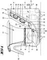
- the kitchen machine 1 shown in Figure 1 has a housing 2, which consists essentially of two Areas composed.
- the first, lower area is a mixing vessel receiving area 3 from which one at an angle of approx. 60 degrees to the horizontal upward extending operator and Electronics area 4 extends.
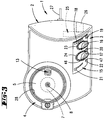
- the mixing vessel receiving area 3 has a circular shape Recording 5 for a stirring vessel 6. Furthermore is in this area 3 a drive motor 7 coaxial with the recording 5 assigned, via which by means of a drive shaft 8 a arranged in the stirring vessel 6 Agitator 9 can be put into operation.
- the stirring vessel 6 is in the inserted state the handle facing away from the operator and electronics area 4 10 provided. Furthermore, the mixing vessel 6 a lid 11 which, for example, by means of brackets or the like on the stirring vessel 6 is held.
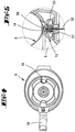
- the provided with feet 12 housing 2 has in Bottom area of the receptacle 5 a temperature sensor 13, which when the mixing vessel is inserted into the receptacle 5 kicks against the bottom of the pot 14.
- the temperature sensor 13 essentially has a covered sensor head 50, which is always in the direction by means of a compression spring 51 on the bottom of the pot 14, i.e. vertically upwards, is burdened.
- Both the one with an electrical connection 52 provided sensor head 50 as well as the compression spring 51 are accommodated in a housing 53, which in Bottom area of the receptacle 5 is fixed (see figure 5).
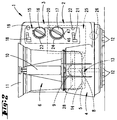
- Operator display 15 In the operator and electronics area 4 is in the Stirring vessel 6 facing surface of the housing wall Operator display 15 provided.
- the latter includes a rotary switch 16 for a temperature preselection, one another rotary switch 17 for preselecting a speed of the Agitator 9, an electronic clock 18 with one for Setting this clock 18 serving rotary switch 19, a button 20 to achieve a turbo switching and an electronic weight display 21 with one of these Display assigned reset button 22.
- the rotary switch 16 and 17 for temperature or speed setting each illuminated by an LED display 23, 24, each display having 23, 24 set points.
- the electrical cable connection to supply the food processor 1 is designated by the number 27.
- the lower region of the mixing vessel 6 is in the region of the Recording 5 of the housing 2 can be heated. To do this the food processor 1 in the area of the receptacle 5 electric resistance heater 28 which the lower Area of the mixing bowl 6 encloses.
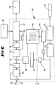
- FIG 6 is a block diagram of the control of the Resistance heater 28 shown.
- the desired temperature is via the rotary switch 16, which as a linear Potentiometer is designed, set and as Voltage value via an analog / digital converter Control circuit 29 supplied as a target value.
- the temperature sensor 13 measures the current temperature at the bottom of the pot 14 and reports after running through a linearization module 30 the determined actual value the control circuit 29. Since the current temperature at the bottom of the vessel is determined then a correction of the determined value in a temperature compensation module 31, in which a Factor, calculated according to the heat transfer numbers becomes. The actual value corrected in this way corresponds thus the actually essential material temperature.
- This actual value becomes the target value in a comparator 32, for example a differential amplifier.
- the heating is controlled depending on the setpoint, with specifications from 40 ° C to 60 ° C with less Controlled energy than with specifications of more than 60 ° C becomes.
- a proportionality module 33 provided in which depending on the specification of the target value Proportionality factors can be selected. Prefers are factors that are specified at 40 ° C up to 60 ° C a value of 1.6 and with specifications of more than 60 ° C corresponds to a value of 2.8.
- This proportionality module 33, a fuse module 34 is connected downstream, which ensures that a temperature of 100 ° C is not exceeded.
- the determined Data about another proportionality module 35 and a filter 36 forwarded to a control module 37.
- a generator acts on this control module 37 38, preferably a sawtooth generator, which in works every 15 seconds.
- Control module 37 a correspondingly lasting for 15 seconds Control window opened, in which one Control of the power consumption of the resistance heating 28 takes place.
- a clock generator 39 is provided for this purpose, which is the data between the second proportionality module 35 and the filter 36 taps and in one Can flow into the control module 37 every second.
- the control module 37 For example, is a high heat output or great energy is required, so within the 15th Second window of the control module 37, for example a 12 second high signal delivered. Over the remaining three seconds correspondingly a low signal. These signals correspond for example the amount of resistance heating 28 applied voltage. However, it is a lower one Energy is required, e.g. within the 15 second window is only 5 seconds long high signal delivered, followed by 10 seconds persistent lower signal. It is also conceivable the resistance heater within the set window 28 completely on or off. The power consumption the resistance heater 28 is thus in regulated a time interval of 15 seconds, where within these 15 seconds periods of high and low signals are provided.
- the regulation of the heating output is still from the Temperature rise rate affected.
- the actual values determined after the temperature compensation module 31 tapped and, after run a filter 40 to a temperature rise rate module 41 forwarded.
- the determined here Values become an intermediate via a coupling point 42 the security module 34 and the second proportionality module 35 arranged comparators 43, for example in the form of a differential amplifier.
- the latter now determines that to the control module 37 value to be derived from the values of the first proportionality module 33 and the coupling point 42.
- a filling quantity determination also influences the Control of heating power.
- a branch is provided for this, which is also the data after the temperature compensation module 31 taps and, after a predetermined time after switching on the agitator 9, for example 2 minutes, this signal on a filling quantity determination module 44 switches.
- the result of The filling quantity is determined in an evaluation unit 45 in Relation to the preset speed of the agitator 9, which is adjustable via the rotary switch 17 is set.
- the ratio is determined in the filling quantity determination module 44 of supplied heating energy to increase the temperature determines what a conclusion on the filling quantity allows. However, since at different speeds of the Agitator 9 different heat transfer resistances there is a correct filling quantity determination required. This takes place in the already mentioned Evaluation unit 45.
- the value thus determined is compared with the Contents of a characteristic field compared.
- the content the characteristic field is based on empirically determined Measured values, which with different fillings with different Temperature rise values and speeds were determined.
- the empirically determined values are saved in a non-volatile memory.
- the corrected resulting from the evaluation unit 45 Filling quantity is given as a value to that already mentioned Coupling point 42 forwarded where a link of these values with the temperature rise rate values he follows.
- the resistance heater 28 is thus controlled in addition to the usual target / actual value comparison by the Determination of the rate of temperature rise and the filling quantity.
- the control is designed so that regardless of the thermal conductivity and the amount of heating Stirred goods in the mixing vessel 6 a more even Heating takes place.
- FIG. 7 there is an example of a temperature rise curve shown.
- Figure 8 shows the line the power consumption at the same time unit as in the temperature characteristic.
- T1 is the preset maximum temperature featured.
- P1 denotes the maximum in FIG Power consumption.
- an agitator setting can be selected, which starts a dough mixer.
- this agitator setting is the rotary switch 17th from a zero position 46 counterclockwise twisted into a dough stirring position 47.
- stirring phases due to regular stoppages interrupted. The latter extend in comparison about three times the stirring phases, preferably a rest period of 4.5 seconds compared to a stirring phase of 1.5 seconds is.
- Advantage of this dough mixer is that the dough to be stirred is in the stirring phases can put again.
- the circuit is like that too advantageous that they are used for engine cooling can. In the stirring phase, therefore, can be short-term realize very high speeds.
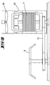
- the rest phases are used for active Cooling of the drive motor 7 by means of one in one Air duct 62 arranged, separate cooling fan 60 (see Fig. 9).
- the drive motor 7 is standing Universal motor (series motor) designed and also positioned in the area of the air duct 62. This drives the agitator 9 via a belt 61.
- the motor is supplied with mains voltage and via a Triac driven.
- the engine is here designed so that when using the device maximum intended load a sufficient rotational movement (Circulation in the production of dough) guaranteed is.
- the external cooling fan 60 generates during the maximum air output in this operating mode, however alone is not enough for the drive motor 7 below the limit prescribed for use to cool down the temperature.
- the duration (pulse width) of the control pulse is sufficiently designed so that for the Use of the device the maximum intended load necessary work is done.
- the ratio of Pulse width of the control pulse for the motor in each case subsequent off time is set so that at maximum air output of the external cooling fan 60 and at the maximum intended load for a particular Duration the prescribed for the use of the device Limit temperature of the motor windings not exceeded becomes.
- the cooling fan shown schematically in FIG. 9 60 is via its own electric motor, not shown driven.
- the Drive motor 7 With a basic or normal load, as with the majority Device applications is used, the Drive motor 7 within its characteristic by phase control regulated to the required speeds. For the necessary cooling is provided by the external cooling fan 60, where the air output of the heat development in the drive motor 7, measured by a temperature sensor, not shown in the drive motor 7, by electronic control is adjusted.
- Both the dough agitator circuit and the turbo circuit can only be activated if the heating temperature preset below a certain limit temperature is.
- a limit temperature is preferred here of 70 ° C. This is due in particular to the fact that already locally at temperatures of more than 70 ° C Boiling phenomena can occur, which are caused by the Stirring function can be strengthened. This can happen at very high Speeds, which both in the dough mixer and can also occur in the turbo circuit cause that a very strong pressure builds up and the Lid of the mixing vessel is lifted off.
- electronics cause that depending on a preset speed of the agitator 9 Start up the agitator 9 to this speed initially slowly and then faster. For this purpose, that at a preset speed of up to about 1000 revolutions per minute always a slow one Start-up takes place. At higher speeds, above about 1000 revolutions per minute a jerky start. However, is the heating temperature set to greater than 70 ° C, so also at a setting of a rotational speed of more than 1,000 rpm a slow start and the speed nevertheless does not exceed 1,000 rpm.
- the Speed change during normal operation i.e. at constant speed of the agitator, without gear. The change in speed is determined by means of a Control over the leading edge angle made.
- High speeds of more than 1,000 rpm are used in the most applications for crushing the pot content set. You need the maximum torque of the drive motor 7 to prevent wedging when starting to avoid the mixing tool in the medium. Of the available drive motor 7 can the maximum Apply torque only at maximum supply voltage, d. H. Start without leading edge and then open regulate the target speed. Low speeds of less than 1,000 rpm are mainly used in cooking used for stirring. Here a crushing of the Pot contents can be avoided in which the drive motor 7 with low supply voltage (maximum leading edge) started and then regulated to the target speed becomes.
- the speed control is via a microprocessor implemented programmatically.
- the setpoint is specified continuously via the rotary switch already mentioned 17, which is designed as a potentiometer.
- the feedback about the actual value a sensor that detects the rotational movements of the drive motor 7 taps on the motor shaft.
- the interpretation of the Components determining the control loop are of such a nature that that a control range of at least 1: 100 is reached is, d. H. Speeds of z. B. 100 to about 10,000 RPM on the mixing tool.
- Said switches 16 and 17 for presetting Temperature and speed are, as already mentioned, means LED displays 23, 24 illuminated. These lights have a signal effect for the user, since at higher Setting values a lighting of a different color and / or Intensity is assigned than at lower ones Setting values. It is particularly provided here that the LED displays 23, 24 are designed in two colors, where a yellow area indicates the lower setting values and a red one is assigned to the higher setting values is. While at the lower setting ranges yellow LEDs are strongly activated, the red ones are only weak, takes place with increasingly higher settings a weakening of the activation of the yellow and an increase in the activation of the red LEDs.
- Light emitting components such as B. feed LED's Light from opposite directions in a light guide on.
- the light guide is designed so that Light emitted perpendicular to the direction of the feed the effect of a light bar.
- the feed components LEDs
- the electrical arranged in the operator display 15 Clock 18 has a rotary switch 19 for preselection a heating time and / or a stirring time.
- the setting the clock 18 is done in the simplest way by due to a high rotational speed of the rotary switch 19 a large unit of time over a certain angle of rotation, for example one minute, and a lower one Speed of rotation of the rotary switch 19 over the same angle of rotation a low time unit, for example a second that is assignable. This means, that via the rotary switch 19 both an adjustment in small as well as large steps is possible without drive through the entire setting range have to.
- the one located at the rear of the housing 2 Collective connector 26 is designed as an interface.
- electrical / electronic and / or mechanical components query loops be brought together.
- functional failures in the main components, like motor 7 and heater 28, or other electrical Elements can be detected.
- Error messages So e.g. also voltage drops in the motor windings or in the electronic elements, with which a targeted troubleshooting is realized.
- EEPROM non-volatile memory
- a part of the calibration circuit can be used for this Query loop of an electrical / electronic component the food processor 1 in a removable and pluggable housing part.
- a housing part in terms of Programmable calibration values and designed as dongle.
- EEPROM non-volatile Memory
- a calibration can be carried out in such a way that the dongle placed on the collector plug 26 or the interface and then the food processor 1 is switched on becomes.
- the time display 18 shows the respective calibration step on, preferably ten steps carried out become.
- the scale display 21 shows in the various Calibration steps to be set Characteristic data, such as when tare the scale one point. After switching on the food processor 1 for The balance display 21 first shows the calibration Version number of the dongle. Is the food processor 1 earlier with an older one Dongle version has been calibrated, the version number flashes in the scale display 21. After completing a The reset button 22 becomes every calibration step to move to the next calibration step reach.
- the collector plug 26 can also serve as an interface for be a computer.
- the over the query loops determined values can thus be from a Computers can be recorded and evaluated.
- Based on this determined and by Computer captured data can also be found in the computer stored target data comparisons are made, according to which the user can use the computer to operate incorrectly, such as set too high Temperature or speed, can be communicated.
- the interface or the common connector 26 to a computer-assisted operation of the To use food processor 1.
- the computer for example after filling predetermined ingredients into the mixing vessel 6 the computer the speed of the agitator 9, the Temperature of the resistance heater 28 and the duration of the Determine, regulate and control stirring or heating.
Abstract
Description
Die Erfindung betrifft eine Küchenmaschine mit einem Rührgefäß und einem Antrieb für ein Rührwerk in dem Rührgefäß, wobei das Rührgefäß in seinem unteren Bereich aufheizbar ist.The invention relates to a food processor with a Stirring vessel and a drive for an agitator in the Stirring vessel, the stirring vessel in its lower area is heatable.
Eine derartige Küchenmaschine ist beispielsweise aus der DOS 35 072 76 bekannt. Insbesondere ist es auch erwünscht, solche Küchenmaschinen zur Teigherstellung zu nutzen. Hierbei kommen bekannte Küchenmaschinen jedoch immer rasch an ihre Grenze, da eine sehr hohe Leistungsaufnahme und damit eine starke Erwärmung des Motors einhergeht.Such a kitchen machine is, for example, from the DOS 35 072 76 known. In particular, it is desirable such kitchen machines for making dough to use. Well-known kitchen machines come here however always quickly to their limits, since a very high one Power consumption and thus a strong warming of the Motors goes hand in hand.
Aufgabe der vorliegenden Erfindung ist es, eine wie eingangs angegebene Küchenmaschine in vorteilhafter Weise weiterzubilden.The object of the present invention is a how Food processor specified in the beginning in an advantageous Way to train.
Diese Aufgabe ist zunächst und im wesentlichen beim
Gegenstand des Anspruches 1 gelöst.This task is first and foremost
Subject matter of
Es wird vorgeschlagen, daß eine Rührwerk-Einstellung (Teigrührschaltung) vorgesehen ist, in welcher Rührphasen durch regelmäßige Stillstände unterbrochen sind. Diese Teigrührschaltung kann mittels des Einstellschalters für die Drehzahl des Rührwerkes geschaltet werden, wobei hier eine Ausgestaltung bevorzugt wird, bei der eine Einstellung in die Teigrührachaltung von einer Nullstellung ausgehend in Gegenuhrzeigerrichtung und eine übliche Einstellung des Rührwerkes in Uhrzeigerrichtung erfolgt. Somit ist gewährleistet, daß eine Umschaltung von der Teigrührschaltung in eine Normalschaltung, d. h. eine Einstellung einer konstanten Drehzahl des Rührwerkes, nur mit einem Überfahren der Nullstellung erfolgen kann. Diese Teigrührschaltung zeichnet sich durch von Ruhephasen unterbrochenen Rührphasen aus ("Stop and go"). In einer Weiterbildung des Erfindungsgegenstandes ist vorgesehen, daß unter Nutzung eines Rührgutwiderstandes bei einer Reduzierung der sich an sich aus der Leistungsaufnahme ergebenden maximalen Drehzahl auf ein Drittel oder weniger Ruhepausen zwischengeschaltet sind und daß die Ruhepausen zur aktiven Kühlung des Antriebsmotors genutzt sind. Als Antrieb dient hierbei ein Universalmotor oder Reihenschlußmotor. Die Antriebseinheit muß sowohl die Anforderungen für die hohen Drehzahlen erfüllen als auch ein hohes Drehmoment für starke Belastungen aufbringen. Bekannt sind hierbei Lösungen, bei welchen ausreichend starke Motoren mit Direktantrieb eingesetzt werden, deren Kenndaten so ausgelegt sind, daß die geforderten Bedingungen hinsichtlich Drehzahl und Drehmoment erfüllt werden, ohne dabei die jeweils vorgeschriebenen thermischen Grenzwerte zu überschreiten. Nachteilig an dieser Ausgestaltung ist, daß der niert ausgebildet ist, was auch zu einer Vergrößerung des Volumens und einer Zunahme des Gewichtes des Motors zur Folge hat. Zur Kühlung derartiger Motoren werden an sich bekannte Kühllüfter vorgesehen. Hier ist bspw. die EP-PS 0 513 483 zu erwähnen. Weiter sind Ausgestaltungen bekannt, bei welchen zwischen Motor und Abtrieb Getriebe mit festem Übersetzungsverhältnis oder mit verschiedenen Getriebestufen vorgesehen sind. Ein derartiges Getriebe ist mit einer entsprechenden Übersetzung ausgelegt zur Einhaltung der für die einzelnen Komponenten beim jeweiligen Einsatz des Gerätes vorgeschriebenen thermischen Grenzwerte. Der Einsatz von Getriebe bringt einen erhöhten technischen und mechanischen Aufwand mit sich. Das Getriebe muß entsprechend den gestellten Anforderungen bei einem hohen Drehmoment kraftschlüssig und für hohe Drehzahlen sicher gegen Fliehkrafteinflüsse ausgelegt sein. Die durch ein Getriebe entstehenden Reibungsverluste verringern den Wirkungsgrad der gesamten Antriebseinheit. Beim Erfindungsgegenstand ist die Antriebseinheit derart gebildet, daß diese aus einem Motor und einem Getriebe mit fester Übersetzung besteht, wobei der Motor mit entsprechender Ansteuerung, die über die Kenndaten des Motors und des Übersetzungsverhältnisses so ausgelegt ist, daß der gesamte geforderte Drehzahlbereich bei einer Grund- bzw. Normallast, wie sie bei dem überwiegenden Einsatz des Gerätes vorliegt, elektronisch geregelt durchfahren wird und bei einer für die Geräteanwendung maximal vorgegebnen Belastung (bspw. Teigrührschaltung), die weniger oft zum Einsatz kommt, der Motor ungeregelt angesteuert wird und dabei die notwendige Abgabeleistung zur Verrichtung der geforderten Arbeit aufbringt. Die für einen Einsatz der Antriebseinheit vorgeschriebenen thermischen Grenzwerte werden eingehalten. In Einzelheit wird hierzu vorgeschlagen, daß ein stehender Universalmotor (Reihenschlußmotor) über einen Riemen das parallel zum Motor angeordnete Rührwerk antreibt. Der Motor wird mit Netzspannung versorgt und über einen Triac angesteuert. Der Antriebsmotor hat auf seiner Welle keinen Kühllüfter. Vielmehr ist zur Kühlung des Antriebsmotors ein externer elektrischer Gebläsemotor vorgesehen. Bei einer Grund- bzw. Normallast wird der Motor innerhalb seiner Kennlinie durch Phasenanschnitt auf die geforderten Drehzahlen geregelt. Die Verluste der Leistungsabgabe besonders bei hohen Drehzahlen werden durch Wegfall eines Kühllüfters auf der Motorwelle reduziert. Für die notwendige Kühlung sorgt das externe Kühlgebläse, wobei die Luftleistung der Wärmeentwicklung im Motor, gemessen von einem Temperaturfühler im Motor, durch elektronische Regelung angepaßt wird. Die Luftleistung ist bei einer Grundlast für jede Drehzahl angepaßt, die Werte stammen aus empirischen Ermittlungen. Bei erhöhter Last muß zum Erreichen der Solldrehzahl die Motorspannung durch entsprechendes Ansteuern des Triacs erhöht werden. Diese Erhöhung wird als Abweichung zur Spannung bei Grundlast ausgewertet und kann indirekt als Lasterhöhung gedeutet werden. Je größer die Abweichung ist, desto stärker ist die Last und damit auch die Motorerwärmung. Dementsprechend wird dann die Luftleistung durch Ansteuern des Lüftermotors erhöht. Bei hohen Belastungen, wie sie z. B. bei einer Hefeteigzubereitung auftreten, steigt die Motortemperatur aufgrund der erhöhten Verluste in den Kupferwicklungen über den vorgeschriebenen Grenzwert hinaus an. Hierbei wird die an sich maximale Drehzahl von bspw. 11.500 U/min auf eine Drehzahl von 100 bis 3.000, im Mittel ca. 500 U/min reduziert. Die Antriebseinheit, bestehend aus Motor und Getriebe, ist dabei so ausgelegt, daß bei der für den Einsatz des Gerätes maximal vorgesehenen Belastung eine ausreichende Drehbewegung zur Umwälzung bei Herstellung von Teigen oder ähnlichen gewährleistet ist. Das externe Gebläse erzeugt während dieser Betriebsart die maximale Luftleistung, die jedoch allein nicht ausreicht um den Motor unter den für den Einsatz vorgeschriebenen Grenzwert der Temperatur herab zu kühlen. Zusätzlich wird der Motor bei den hohen Belastungen nur mit Impulsen angesteuert, wobei die volle Netzspannung gehalten wird und sich eine der Belastung entsprechende Drehzahl einstellt. Die Dauer (Pulsbreite) des Ansteuerimpulses muß dabei ausreichen, um bei der für den Einsatz des Gerätes maximal vorgesehenen Belastung die notwendige Arbeit zu verrichten. Das Verhältnis der Pulsbreite des Ansteuerimpulses für den Motor zur jeweils nachfolgenden Aus-Zeit ist so festgelegt, daß bei maximaler Luftleistung des externen Kühlgebläses und bei der maximal vorgesehenen Belastung für eine bestimmte Dauer die für den Einsatz des Gerätes vorgeschriebene Grenztemperatur der Motorwicklungen nicht überschritten wird. Aufgrund der Charakteristik eines Universalmotors (Reihenschlußmotors) läuft der Motor bei einem Impulsbetrieb mit jedem Einschaltvorgang mit dem maximal zur Verfügung stehenden Drehmoment aus dem Stillstand an und verursacht so einen für bestimmte Anwendungen nützlichen Losreißeffekt. Bei der Herstellung von Hefeteig oder ähnlichem trägt der Impulsbetrieb durch Losrütteln von Teigbestandteilen zu einer Verbesserung der Rückführung des Teiggemisches in den Arbeitsbereich des Knetwerkzeuges im Rührtopf bei. Es wird hierbei bevorzugt, daß die Stillstände sich im Vergleich zu den Rührphasen über eine vielfache Zeitspanne erstrecken. Die Ruhephase, die bevorzugt etwa dreifach so lang ist wie die Rührphase, beispielsweise ca. 4,5 Sekunden im Vergleich zu 1,5 Sekunden, ist auch dahingehend vorteilhaft, daß sie zur Motorkühlung genutzt werden kann. Es sind Verhältnisse von Ruhephase zu Rührphase im Bereich von 1:1 bis 6:1 denkbar. In der Rührphase lassen sich daher kurzfristig sehr hohe Leistungen realisieren. Die beschriebene Ausgestaltung ist weiterhin dahingehend optimiert, daß die Teigrührschaltung nur aktivierbar ist, wenn die Aufheiztemperatur unterhalb einer bestimmten Grenztemperatur, beispielsweise 70°C voreingestellt ist. Diese Sicherheitsfunktion ist auch bei einer sogenannten Turbofunktion, bei welcher kurzfristig sehr hohe Drehzahlen erzielt werden, denkbar. Die Abhängigkeit von einer bestimmten Grenztemperatur hat insbesondere den Hintergrund, daß bei Temperaturen von mehr als 70°C bereits örtliche Siedeerscheinungen auftreten können, die durch die Rührfunktion verstärkt werden (Siedeverzug). Dies kann bei sehr hohen Drehzahlen, welche sowohl bei einer Teigrührschaltung als auch bei einer Turboschaltung erzielt werden können, dann dazu führen, daß sich ein sehr starker Druck aufbaut, welcher zu einem Abheben eines auf dem Rührgefäß angeordneten Deckels führen kann. Weiterhin erweist es sich als vorteilhaft, daß abhängig von einer voreingestellten Drehzahl des Rührwerkes ein Hochfahren des Rührwerkes auf diese Drehzahl zunächst langsam und dann schneller erfolgt. Hier kann beispielsweise die Ausbildung so gewählt sein, daß bei einer Drehzahl des Rührwerkes bis etwa 1000 Umdrehungen pro Minute stets ein langsames Anfahren erfolgt. Bei größeren eingestellten Drehzahlen, oberhalb etwa 1000 Umdrehungen pro Minute, erfolgt ein ruckartiges Anfahren. Hierzu wird vorgeschlagen, daß bei einer Voreinstellung der Heizung auf eine Temperatur von mehr als 70°C auch bei einer Einstellung von mehr als 1000 Umdrehungen pro Minute ein langsames Anfahren erfolgt, wobei die Drehzahl gleichwohl 1000 Umdrehungen pro Minute nicht überschreitet. Die Drehzahlveränderung des Motors bei normalem Betrieb, d.h. bei konstanter Drehzahl des Rührwerkes, erfolgt bevorzugt ohne Getriebe. Vielmehr wird die Veränderung mittels Steuerung über den Phasenanschnittswinkel vorgenommen. Hohe Drehzahlen von mehr als 1.000 U/min werden bei den meisten Anwendungen zum Zerkleinern des Topfinhaltes eingestellt. Man benötigt hierbei das maximale Drehmoment des Motors, um beim Anlaufen ein Verkeilen des Mixwerkzeuges in dem Medium zu vermeiden. Der zur Verfügung stehende Antriebsmotor kann das maximale Moment nur bei maximaler Versorgungsspannung aufbringen, d. h. ohne Phasenanschnitt starten und dann auf die Solldrehzahl regeln. Niedrigere Drehzahlen von weniger als 1.000 U/min werden überwiegend im Kochbetrieb zum Rühren verwendet. Hier muß ein Zerkleinern des Topfinhaltes vermieden werden, in dem der Motor mit geringerer Versorgungsspannung (maximaler Phasenanschnitt) gestartet und dann auf die Solldrehzahl geregelt wird. Die Drehzahlregelung wird über einen Mikroprozessor programmtechnisch realisiert. Die Sollwertvorgabe erfolgt stufenlos über einen Potentiometer, die Rückmeldung über den jeweiligen Istwert erfolgt durch einen Sensor, der die Drehbewegungen des Motors an der Motorwelle abgreift. Die Auslegung der den Regelkreis bestimmenden Komponenten muß dabei so geartet sein, daß ein Regelbereich von mindestens 1:100 erreicht wird, d. h. Drehzahlen von z. B. 100 bis ca. 10.000 U/min am Mixwerkzeug.It is suggested that an agitator setting (Dough stirring circuit) is provided, in which stirring phases are interrupted by regular downtimes. This dough stirring circuit can be set using the setting switch are switched for the speed of the agitator, an embodiment is preferred here in which a setting in the dough mixing of one Zero position counterclockwise and a usual setting of the agitator clockwise he follows. This ensures that a Switching from the dough agitator circuit to a normal circuit, d. H. a setting of a constant Speed of the agitator, only with one run over Zeroing can take place. This dough mixer is characterized by stirring phases interrupted by resting phases from ("Stop and go"). In a further education of the Subject of the invention is provided that using of an agitated material resistance with a reduction the result of the power consumption maximum speed to a third or less breaks are interposed and that the breaks to active cooling of the drive motor are used. As The drive is a universal motor or series motor. The drive unit must meet both the requirements for the high speeds as well Apply high torque for heavy loads. Solutions are known in which sufficient strong motors with direct drive are used, whose characteristics are designed so that the required Conditions regarding speed and torque met be without doing the prescribed exceed thermal limits. Disadvantageous this embodiment is that the kidney trained is what also leads to an increase in volume and an increase in the weight of the engine. Known are known per se for cooling such motors Cooling fan provided. For example, here is EP-PS 0 513 483 to mention. Further configurations are known in which between the engine and the output gearbox fixed gear ratio or with different Gear stages are provided. Such a transmission is designed with an appropriate translation for Compliance with the requirements for the individual components Use of the device prescribed thermal Limits. The use of gears brings an increased technical and mechanical effort. The Gearbox must meet the requirements with a high torque non-positive and for high Speeds safely designed against centrifugal influences be. The friction losses caused by a gearbox reduce the efficiency of the entire drive unit. The drive unit is the subject of the invention formed such that this from an engine and a gearbox with a fixed gear ratio, where the motor with appropriate control, which via the Characteristics of the engine and the gear ratio is designed so that the entire required speed range with a basic or normal load, as in the predominant use of the device is present, electronically is driven through in a controlled manner and at one for the Device application maximum predetermined load (e.g. Dough stirring circuit), which is used less often, the motor is controlled uncontrolled and the output required to perform the required Brings up work. The one for use of the drive unit prescribed thermal limits are adhered to. In detail, it is proposed that that a stationary universal motor (series motor) via a belt that runs parallel to the engine arranged agitator drives. The motor is powered by mains supplied and controlled via a triac. Of the The drive motor has no cooling fan on its shaft. Rather, an external one is used to cool the drive motor electric blower motor provided. At a Base or normal load is the engine within its Characteristic curve through phase control to the required Regulated speeds. The losses of the power output especially at high speeds due to elimination of a cooling fan on the motor shaft is reduced. For the cooling is provided by the external cooling fan, whereby the air output of the heat development in the engine, measured from a temperature sensor in the engine, by electronic Regulation is adjusted. The air performance is at adapted to a base load for each speed, the values come from empirical investigations. With increased Load must reach the motor voltage to reach the target speed increased by controlling the triac accordingly become. This increase is called a deviation from the tension evaluated at base load and can indirectly as Load increase can be interpreted. The bigger the deviation is, the stronger the load and thus the Engine warming. Accordingly, the air output increased by driving the fan motor. At high loads, such as. B. in a yeast dough preparation occur, the engine temperature rises due to the increased losses in the copper windings over the prescribed limit value. Here, the per se maximum speed of 11,500 rpm a speed of 100 to 3,000, on average approx. 500 RPM reduced. The drive unit consisting of Engine and transmission, is designed so that the maximum intended load for the use of the device a sufficient rotational movement for circulation Production of dough or the like is guaranteed is. The external fan generates during this operating mode the maximum air output, however, alone not enough to use the engine among those prescribed temperature limit cool. In addition, the engine will handle the high loads only controlled with pulses, the full Mains voltage is kept and become a burden sets the appropriate speed. The duration (pulse width) the control pulse must be sufficient to the maximum intended for the use of the device To do the necessary work. The Ratio of the pulse width of the control pulse for the Motor at the subsequent off time is set so that at maximum air flow of the external cooling fan and at the maximum intended load for a certain duration for the use of the device prescribed limit temperature of the motor windings is not exceeded. Because of the characteristics a universal motor (series motor) runs the Motor in pulse mode with every start-up with the maximum available torque from a standstill, causing one for certain Applications useful breakaway effect. In the The production of yeast dough or the like carries the impulse operation by shaking loose dough components an improvement in the return of the dough mixture in the working area of the kneading tool in the mixing bowl. It is preferred that the standstills in the Comparison to the stirring phases over a multiple period of time extend. The resting phase, which is preferred about is three times as long as the stirring phase, for example about 4.5 seconds compared to 1.5 seconds is too advantageous in that they are used for engine cooling can be. They are relationships of the resting phase conceivable for the stirring phase in the range from 1: 1 to 6: 1. In the Mixing phase can therefore be very high performance in the short term realize. The configuration described is further optimized in that the dough stirring circuit can only be activated if the heating temperature below a certain limit temperature, for example 70 ° C is preset. This security function is also in a so-called turbo function, at which very high speeds can be achieved in the short term, conceivable. The dependence on a certain one Limit temperature has in particular the background that already local at temperatures above 70 ° C Boiling phenomena can occur, which are caused by the Stirring function are increased (delay in boiling). This can at very high speeds, which both at a Dough stirring circuit as well as in a turbo circuit can be achieved, then lead to a very strong pressure builds up, which leads to a lifting of a lid arranged on the mixing vessel can. Furthermore, it proves advantageous that depending on a preset speed of the agitator a start up of the agitator to this speed first slowly and then faster. Here can For example, the training should be chosen so that a speed of the agitator up to about 1000 revolutions there is always a slow start-up per minute. At higher set speeds, above about 1000 revolutions per minute, there is a jerky Start off. It is proposed that at a Presetting the heating to a temperature of more than 70 ° C even with a setting of more than 1000 Revolutions per minute there is a slow start, the speed nonetheless 1000 revolutions per Minute does not exceed. The speed change of the Motors in normal operation, i.e. at constant speed of the agitator, preferably done without a gear. Rather, the change is controlled by means of made the leading edge angle. High speeds of more than 1,000 rpm in most applications set to crush the pot content. You need the maximum torque of the motor to wedge the mixing tool when starting to avoid in the medium. The one available Drive motor can only get the maximum torque at maximum Apply supply voltage, d. H. without leading edge start and then adjust to the target speed. Lower speeds of less than 1,000 rpm will be mainly used for stirring in cooking. Here a crushing of the pot content must be avoided in which the motor with a lower supply voltage (maximum leading edge) started and then on the target speed is regulated. The speed control is implemented programmatically via a microprocessor. The setpoint is infinitely variable via a Potentiometer, the feedback on the respective Actual value is done by a sensor that detects the rotary movements of the motor on the motor shaft. The interpretation the components determining the control loop be such that a control range of at least 1: 100 is reached, i.e. H. Speeds of z. B. 100 to approx. 10,000 rpm on the mixing tool.
Weiterhin betrifft die Erfindung eine Küchenmaschine mit einem Rührgefäß und einem Antrieb für ein Rührwerk in dem Rührgefäß, wobei das Rührgefäß in seinem unteren Bereich aufheizbar ist und die Drehzahl und/oder die Temperatur über beleuchtete Schalter, beispielsweise Dreh- oder Schiebeschalter erfolgt. Auch derartig ausgebildete Küchenmaschinen sind bekannt. Hier wird zur Erzielung einer verbesserten Handhabung vorgeschlagen, daß höheren Einstellwerten eine Beleuchtung anderer Farbe und/oder Intensität zugeordnet ist als niedrigeren Einstellwerten. Dies kann beispielsweise dadurch gelöst sein, daß LED-Anzeigen für Temperatur und/oder Drehzahl zweifarbig ausgebildet sind, beispielsweise gelb und rot. Licht emittierende Komponenten wie z. B. LED's speisen Licht von entgegengesetzten Richtungen in einen Lichtleiter ein. Der Lichtleiter ist dabei so ausgelegt, daß Licht senkrecht zur Richtung der Einspeisung abgestrahlt wird und so der Effekt eines Lichtbalkens entsteht. Je nach Ansteuerung der Einspeisekomponenten (LED's) kann so entweder die Intensität von einer Seite des Lichtbalkens zur anderen verlagert werden und erhöht werden (bei gleichfarbigen Einspeisekomponenten) oder bei farblich unterschiedlichen Einspeisekomponenten ein Effekt fließender Veränderung von der Farbe der einen Einspeisekomponente über Mischlicht bis hin zur Farbe der anderen Einspeisekomponente erzielt werden. Für die Drehzahl kann bei zweifach einfarbiger Einspeisung einer niedrigen Drehzahl eine entsprechende Intensität zugeordnet und anzeigt und bei Erhöhung der Drehzahleinstellung die Intensität zum anderen Ende des Lichtbalkens hin verlagert oder erhöht werden. Während bei niedrigeren Einstellbereichen die gelben LED's stark aktiviert sind, die roten dagegen nur schwach, erfolgt mit zunehmend höheren Einstellungen eine Abschwächung der Aktivierung der gelben und eine Verstärkung der Aktivierung der roten LED's. Die beleuchteten Skalenfelder um die Schalter (Potentiometer) besitzen somit eine Signalfunktion für den Benutzer, insbesondere bei höheren Einstellwerten.The invention further relates to a food processor with a mixing vessel and a drive for an agitator in the mixing vessel, the mixing vessel in its lower Is heated and the speed and / or the Temperature via illuminated switches, for example Rotary or slide switch takes place. Even those trained Food processors are known. Here is the achievement proposed improved handling, that higher setting values illuminate others Color and / or intensity is assigned as lower Setting values. This can be done, for example be solved that LED displays for temperature and / or Speed are formed in two colors, for example yellow and red. Light emitting components such as B. LEDs feed light from opposite directions a light guide. The light guide is like this designed that light perpendicular to the direction of the feed is emitted and so the effect of a light bar arises. Depending on the control of the feed components (LEDs) can either be the intensity of shifted one side of the light bar to the other and will be increased (with feed components of the same color) or with differently colored feed components an effect of fluid change from the color of one feed component via mixed light down to the color of the other feed component become. The speed can be double colored Infeed of a low speed a corresponding one Intensity assigned and displayed and when increasing the speed setting the intensity to the other Be shifted towards the end of the light bar or increased. While at lower setting ranges the yellow LEDs are strongly activated, the red ones only weak, takes place with increasingly higher settings a weakening of the activation of the yellow and one Enhancement of the activation of the red LEDs. The illuminated Scale fields around the switches (potentiometers) thus have a signal function for the user, especially with higher setting values.
Es ist des weiteren vorgeschlagen, daß bei Küchenmaschinen mit einem Rührgefäß und einem Antrieb für ein Rührwerk in dem Rührgefäß, wobei das Rührgefäß in seinem unteren Bereich aufheizbar ist und ein Drehschalter, insbesondere für eine eingebaute, elektronische Uhr, beispielsweise zur Vorwahl einer Heizzeit, vorgesehen ist, den Drehachalter derart auszubilden, daß durch eine hohe Drehgeschwindigkeit des Drehschalters über einen bestimmten Drehwinkel eine große Zeiteinheit, beispielsweise eine Minute, und durch eine niedrigere Drehgeschwindigkeit des Drehschalters über denselben Drehwinkel eine niedrige Zeiteinheit, beispielsweise eine Sekunde, zuordbar ist. In Abhängigkeit von der Drehgeschwindigkeit eines derartigen Dreh-Stellknopfes über denselben Drehwinkel ist eine Verstellung der Uhr in kleinen wie auch in großen Schritten möglich, ohne jeweils den gesamten Einstellbereich durchfahren zu müssen.It is further proposed that in food processors with a mixing vessel and a drive for an agitator in the stirring vessel, the stirring vessel in its lower area can be heated and a rotary switch, especially for a built-in electronic clock, for example to preselect a heating time is to design the rotary switch so that by a high speed of rotation of the rotary switch a certain angle of rotation a large unit of time for example one minute, and a lower one Rotational speed of the rotary switch above the same Angle of rotation a low unit of time, for example a second that is assignable. Depending on the Rotational speed of such a rotary control knob The clock is adjusted via the same angle of rotation in small as well as in large steps possible without drive through the entire setting range have to.
Weiter wird bei Küchenmaschinen mit einem Rührgefäß und einem Antrieb für ein Rührwerk in dem Rührgefäß, wobei das Rührgefäß in seinem unteren Bereich aufheizbar ist, vorgeschlagen, daß bezüglich der elektrischen/elektronischen und/oder mechanischen Komponenten Abfrageschleifen vorgesehen sind, die zur Abtragung in einem Sammelstecker zusammengeführt sind. Dieser Sammelstecker kann auch als Schnittstelle für externe Anschlüsse ausgelegt sein. Mittels dieses Sammelsteckers bzw. dieser Schnittstelle können über Abtrageschleifen Meldungen, auch Fehlermeldungen, des Motors, der Heizung, der Uhr, einer eventuell vorgesehenen Waage usw. abgefragt werden, bspw. als Service-Hilfe. Hier können z.B. Funktionsausfälle in den Hauptkomponenten wie Motor oder Heizung oder in anderen elektrischen Elementen erfaßt werden, welche Rückschlüsse auf eventuelle Fehler zulassen. Eine derartige Schnittstelle kann weiterhin dazu genutzt sein, daß ein Teil einer Kalibrierschaltung bzgl. jeder Abtrageschleife einer elektrischen/elektronischen Komponente der Küchenmaschine in einem herausnehmbaren/steckbaren Zusatzteil ausgebildet ist. Es besteht somit die Möglichkeit über diese Schnittstelle nach der Gerätefertigung gerätespezifische Werte einzustellen bzw. zu kalibrieren. Auf diese Weise kann auf aufwendige elektrische/mechanische Justiervorgänge und entsprechende elektrische/mechanische Bauelemente verzichtet werden. Die jeweiligen, gerätespezifischen Werte werden dabei in einem nicht flüchtigen Speicher (EEPROM) in der Elektronik des Gerätes gespeichert und können im Servicefall geändert werden. Bspw. kann bei einer derartigen Kalibrierung die Waageneinrichtung justiert werden und die Soll-Drehzahlen mit den Ist-Drehzahlen des Rührwerkes verglichen werden. Entsprechende Abweichungen könnten in dein nicht flüchtigen Speicher abgelegt werden. Hierzu ist weiterhin denkbar, daß das Steckerteil hinsichtlich der Kalibrierungswerte ebenfalls programmierbar ist. Das Steckerteil kann bspw. in Form eines Dongles ausgebildet sein, welcher werkseitig programmiert ist. Mit Hilfe dieses Steckerteiles, welches auf die Schnittstelle der Küchenmaschine gesetzt werden kann, werden Kalibrierungen vorgenommen und ggf. Voreinstellungen, bspw. der Waage, der Drehzahlen usw., geändert. Es kann hierbei vorgesehen sein, daß die Kalibrierung mittels des Steckerteiles in mehreren Schritten erfolgt, wobei jeder Schritt bspw. in einem Uhrzeit-Display angezeigt wird. Weiter kann bspw. in dem Gewichts-Display die jeweiligen Einstellungswerte angezeigt werden. Es wird vorgeschlagen, daß bspw. in dem Gewichts-Display die Versionsnummer des Steckerteiles, insbesondere des Dongles angezeigt wird. Sollte die Küchenmaschine bereits vorher mit einer älteren Dongle-Version kalibriert worden sein, wird vorgeschlagen, daß die angezeigte, alte Versionsnummer blinkt. Hier ist weiterhin von Bedeutung, daß der Sammelstecker als Schnittstelle für einen Computer ausgebildet ist. Die ermittelten bzw. abgefragten Werte der elektrischen und/oder mechanischen Komponenten können somit mit einer entsprechenden Computer-Software verwertet werden. Hier ist es beispielsweise denkbar, Meßwerte von Prüfschleifen mit computerseitig gespeicherten Soll-Werten zu vergleichen, um eine eventuelle Fehleridentifikation zu ermöglichen. Weiterhin ist bedingt durch diese Ausgestaltung auch denkbar, die aktuelle Temperatur, insbesondere die Rührguttemperatur, die aktuelle Drehzahl des Rührwerkes, die Rührzeit und ein eventuell erfaßtes Füllmengengewicht computerseitig zu erfassen und abzuspeichern. Somit kann auch nach einer Herstellung von Speisen wie Soßen, Suppen oder dergleichen mittels der Küchenmaschine das Herstellungsverfahren, insbesondere die Einstellungen und Dauer der zuvor genannten Konponenten, nachvollzogen werden. Dies ist insbesondere zur Herstellung von Rezepturen besonders vorteilhaft. Schließlich kann eine derartige Schnittstelle für einen Computer auch dahingehend genutzt werden, daß die Komponenten oder die Schnittstelle ansteuerbar sind, beispielsweise die Drehzahl des Rührwerkes vorwählbar oder die Aufheiztemperatur der Heizung einstellbar ist. Es ist somit eine Möglichkeit gegeben, die Küchenmaschine computergesteuert zu nutzen. So kann beispielsweise mit einer computerseitig abgespeicherten Rezeptur die Drehzahl des Rührwerkes und die Aufheiztemperatur der Heizung mittels des Computers eingestellt werden, Weiterhin ist durch diese Ausgestaltung denkbar, daß in Abhängigkeit von den übermittelten Daten dem Benutzer per Computer-Bildschirm Hinweise für den Ablauf einer Speisenzubereitung gegeben werden können.Next is in kitchen machines with a mixing bowl and a drive for an agitator in the mixing vessel, wherein the lower part of the mixing vessel can be heated, suggested that regarding electrical / electronic and / or mechanical components are provided for removal in a common plug are merged. This collective plug can also designed as an interface for external connections be. By means of this common plug or this interface can send messages via ablation loops, too Error messages, the engine, the heating, the clock, a possibly provided balance etc. are queried, For example, as service help. Here e.g. Functional failures in the main components like engine or Heating or detected in other electrical elements which allow conclusions to be drawn about possible errors. Such an interface can also be used be used that part of a calibration circuit with regard to each removal loop of an electrical / electronic Component of the food processor in a removable / pluggable Additional part is formed. It exists thus the possibility via this interface after the Device manufacturing to set device-specific values or to calibrate. In this way it can be expensive electrical / mechanical adjustment processes and corresponding no electrical / mechanical components become. The respective, device-specific values are thereby in a non-volatile memory (EEPROM) in the electronics of the device and can be stored in the Service case to be changed. E.g. can with such Calibration the balance device can be adjusted and the target speeds with the actual speeds of the Agitator are compared. Corresponding deviations could be stored in your non-volatile memory become. It is also conceivable that the plug part with regard to the calibration values as well is programmable. The plug part can, for example, in the form a dongle, which is factory-made is programmed. With the help of this connector, which placed on the interface of the food processor calibrations are carried out and if necessary Presets, e.g. the scale, the speeds, etc., changed. It can be provided that the Calibration using the connector part in several Steps take place, each step, for example, in one Time display is shown. Further, for example, in the respective setting values on the weight display are displayed. It is proposed that, for example, in the weight display shows the version number of the connector part, especially the dongle is displayed. Should the food processor with an older one Dongle version has been calibrated, it is suggested that the displayed old version number is flashing. It is also important here that the header is designed as an interface for a computer. The determined or queried values of the electrical and / or mechanical components can thus appropriate computer software. Here, for example, it is conceivable to measure values of Test loops with target values stored on the computer compare to a possible error identification to enable. Furthermore, is due to this Design also conceivable, the current temperature, in particular the temperature of the mix, the current speed of the agitator, the stirring time and a possibly recorded fill quantity weight to be recorded on the computer and save. Thus, even after a production of dishes such as sauces, soups or the like the manufacturing process using the food processor, especially the settings and duration of the previous mentioned components are reproduced. This is especially for the production of recipes advantageous. Finally, such an interface also used for a computer that the components or the interface can be controlled, for example the speed of the agitator selectable or the heating temperature of the heating is adjustable. It is therefore a possibility given to use the food processor under computer control. For example, with a computer stored recipe the speed of the agitator and the heating temperature of the heater by means of the computer Be set further, by this Design conceivable that depending on the transmitted data to the user via computer screen Instructions for the process of preparing a meal can be given.
Hinsichtlich der Aufheizung des Rührgefäß in seinem
unteren Bereich kann auch vorgesehen sein, daß die
Aufheizung in Abhängigkeit einer Temperaturanstiegsgeschwindigkeit
vorgenommen wird. Die gewünschte Temperatur
wird bevorzugt in bekannter Weise über ein lineares
Potentiometer eingestellt und als Spannungswert einem
Regelkreis als Soll-Wert zugeführt. Hierbei kann eine
Umwandlung des Spannungswertes in einen Soll-Wert beispielsweise
über einen Analog/Digitalwandler eines
integrierten Schaltkreises erfolgen. Ein vorzugsweise
außen an dem Topfboden des Rührgefäßes angeordneter,
beziehungsweise diesen beaufschlagender Temperatursensor
mißt die aktuelle Temperatur und führt diesen als
Ist-Wert dem Regelkreis zu. Es ist somit ein äußerer
Temperaturregelkreis geschlossen. Gleichzeitig wird
während des Aufheizvorganges die Temperaturanstiegsgeschwindigkeit
berechnet, um damit ebenfalls die Heizenergie
zu beeinflussen. Im Gegensatz zu der bekannten
linearen Leistungsaufnahme der Heizung, bewirkt die
erfindungsgemäße Ausgestaltung eine Anpassung der Leistungsaufnahme
in Abhängigkeit von der Temperaturanstiegsgeschwindigkeit.
Wird beispielsweise eine relativ
geringe Temperaturanstiegsgeschwindigkeit ermittelt, so
wird über einen integrierten Schaltkreis oder dergleichen
ein optimaler Leistungsaufnahmewert berechnet,
welcher hier relativ groß ist. Die relativ geringe
Temperaturanstiegsgeschwindigkeit läßt auf ein schwer
aufheizbares Medium innerhalb des Rührgefäßes schließen,
womit zum Aufheizen dieses Mediums entsprechend
mehr Energie zugeführt werden muß. Ist jedoch ein wasserähnliches
Medium vorhanden, so bedingt dies eine
relativ hohe Temperaturanstiegsgeschwindigkeit. Dementwert
berechnet. Als besonders vorteilhaft erweist es
sich hierbei, daß die Aufheizung in Abhängigkeit einer
Füllmengenermittlung durchgeführt wird. Bedingt durch
diese Ausgestaltung ist eine optimale Auslegung der
Leistungsaufnahme der Heizung gewährleistet. Letztere
wird in Abhängigkeit von Füllmenge, Temperaturanstiegsgeschwindigkeit
und Soll/Ist-Wertevergleich geregelt.
Diese Regelung wird dadurch optimiert, daß die Füllmengenermittlung
durch die Temperaturanstiegsgeschwindigkeit
bei einer bestimmten Heizleistung mit empirisch
bei verschiedenen Füllungen ermittelten Temperaturanstiegswerten
durchgeführt wird. Es wird hierbei vorgeschlagen,
die Füllmengenermittlung etwa in der zweiten
Minute nach Einschalten des Aufheizvorganges durchzuführen,
um die Totzeit/Trägheit des Heizsystems zu überbrücken.
Das Verhältnis von zugeführter Heizenergie zur
Temperatursteigung läßt einen Rückschluß auf die Füllmenge
zu. Die ermittelten Vergleichswerte werden mit
empirisch bei verschiedenen Füllungen ermittelten Werten
verglichen. Entsprechend den Vergleichswerten wird
die Leistungsaufnahme geregelt. Es ist vorgesehen, daß
die Füllmengenermittlung weiter in Abhängigkeit der
gewählten Drehzahl des Rührwerkes durchgeführt wird.
Bei verschiedenen Drehzahlen des Rührwerkes ergeben
sich bei gleichem Medium unterschiedliche Wärmeübergangewiderstände.
Bedingt durch die vorgeschlagene
Ausbildung wird die Drehzahl des Rührwerkes mit in die
Füllmengenermittlung einbezogen. Mit der ermittelten
Füllmenge in Verbindung mit der aktuellen Drehzahl des
Rührwerkes werden aus einem empirisch ermittelten Kennlinienfeld
Werte entnommen, mit denen die Heizenergie
beeinflußt wird. Letztere ist somit füllmengenabhängig.
Die empirisch ermittelten Werte basieren auf verschiedenen
Temperaturanstiegswerten bei verschiedenen, üblichen
Füllungen des Rührtopfes, wobei hier Toleranzen
gegeben sind. Bevorzugt wird hierbei eine Ausbildung,
bei der ein nicht flüchtiger Speicher vorgesehen ist,
in welchem die empirisch ermittelten Werte gespeichert
sind. Letzterer kann innerhalb eines integrierten
Schaltkreises vorgesehen sein. Die Regelung der Leistungsaufnahme
ist in vorteilhafter Weise noch dadurch
verbessert, daß Proportionalitätsfaktoren, welche die
Aufheizung steuern, je nach gewünschter Endtemperatur
unterschiedlich gewählt sind. So kann die Heizung beispielsweise
soll-wertabhängig angesteuert werden, d.h.
beispielsweise bei Vorgaben von 40°C bis 60°C mit einer
geringeren Energie als bei Vorgaben von über 60°C.
Weiterhin wird vorgeschlagen, daß die Aufheizung durch
eine elektrische Widerstandsheizung erfolgt und daß die
hierfür erforderliche Energieaufnahme jeweils in einem
der Heizleistung angepaßtem Zeitintervall von beispielsweise
15 Sekunden geregelt ist. Die Leistungsaufnahme
wird dadurch beeinflußt, daß innerhalb eines, beispielsweise
mittels eines Sägezahn-Generators gebildeten Zeitfensters
von 15 Sekunden die Ansteuerdauer der Heizung
variiert wird. Ist beispielsweise eine volle Leistungsaufnahme
erforderlich, so entspricht die Ansteuerdauer
der Heizung dem Zeitintervall, bzw. der des Zeitfenster.
Ist jedoch eine geringere Leistungsaufnahme erforderlich,
so kann beispielsweise die Ansteuerdauer der
Heizung 5 Sekunden betragen. In den bei einem Zeitintervall
von 15 Sekunden verbleibenden restlichen 10 Sekunden
ist die Leistungsaufnahme der Heizung unterbrochen.
Bedingt durch die zuvor beschriebenen Ausgestaltungen
ergibt sich eine optimale Regelung der Leistungsaufnahme
der Heizung in Abhängigkeit von Temperaturanstiegsgeschwindigkeit,
Füllmenge und Drehzahl des Rührwerkes.Regarding the heating of the mixing vessel in his
lower area can also be provided that the
Heating depending on a rate of temperature rise
is made. The desired temperature
is preferred in a known manner over a linear
Potentiometer set and a voltage value
Control loop supplied as target value. Here, a
Conversion of the voltage value into a target value, for example
via an analog / digital converter
integrated circuit. A preferred
arranged on the outside of the pot bottom of the mixing vessel,
or this temperature sensor acting on it
measures the current temperature and lists it as
Actual value to the control loop. It is therefore an external one
Temperature control loop closed. At the same time
the rate of temperature rise during the heating process
calculated to also use the heating energy
to influence. In contrast to the known one
linear power consumption of the heating, causes the
Design according to the invention an adjustment of the power consumption
depending on the rate of temperature rise.
For example, becomes a relative
low rate of temperature rise determined, so
is through an integrated circuit or the like
calculates an optimal power consumption value,
which is relatively large here. The relatively minor
Temperature rise rate leaves on a difficult
close the heatable medium inside the mixing vessel,
with which to heat this medium accordingly
more energy needs to be supplied. However, it is a water-like
Medium is present, this requires one
relatively high rate of temperature rise. Dement value
calculated. It proves to be particularly advantageous
here that the heating depending on a
Filling quantity determination is carried out. Due
this configuration is an optimal interpretation of the
Power consumption of the heating guaranteed. Latter
becomes dependent on the filling quantity, temperature rise rate
and target / actual value comparison regulated.
This regulation is optimized in that the filling quantity determination
by the rate of temperature rise
at a certain heating output with empirical
temperature rise values determined with different fillings
is carried out. It is suggested that
the filling quantity determination in the second
Minute after switching on the heating process,
to bridge the dead time / inertia of the heating system.
The ratio of supplied heating energy to
Temperature rise allows a conclusion to be drawn about the filling quantity
to. The determined comparison values are with
Values determined empirically for different fillings
compared. According to the comparison values
regulated the power consumption. It is provided that
the filling quantity determination depending on the
selected speed of the agitator is carried out.
Result at different speeds of the agitator
different heat transfer resistances with the same medium.
Due to the proposed
Training will include the speed of the agitator in the
Filling quantity determination included. With the determined
Filling quantity in connection with the current speed of the
Agitator are from an empirically determined field of characteristics
Values taken with which the heating energy
being affected. The latter is therefore dependent on the filling quantity.
The empirically determined values are based on various
Temperature rise values at various, common
Fillings in the mixing bowl, with tolerances here
given are. Training is preferred here,
in which a non-volatile memory is provided,
in which the empirically determined values are stored
are. The latter can be integrated within an
Circuit be provided. The regulation of power consumption
is still advantageous in this way
improves that proportionality factors which the
Control heating, depending on the desired end temperature
are chosen differently. For example, the heating
should be controlled depending on the value, i.e.
for example, with specifications from 40 ° C to 60 ° C with a
less energy than with specifications of over 60 ° C.
It is also proposed that the heating by
an electrical resistance heating is carried out and that the
required energy consumption in one
the time interval adapted to the heating power, for example
15 seconds is regulated. The power consumption
is influenced by the fact that within one, for example
time window formed by a sawtooth generator
the activation time of the heating of 15 seconds
is varied. For example, is a full power consumption
required, the activation duration corresponds
the heating the time interval or that of the time window.
However, if less power is required,
for example, the control duration of the
Die Erfindung ist nachstehend anhand eines zeichnerisch veranschaulichten Ausführungsbeispieles näher erläutert. Es zeigt:
- Fig. 1
- eine erfindungsgemäße Küchenmaschine mit einem Rührgefäß in einer Seitenansicht,
- Fig. 2
- die
Küchenmaschine gemäß Figur 1 in Vorderansicht, - Fig. 3
- die Küchenmaschine in Draufsicht, jedoch nach Abnahme des Rührgefäßes,
- Fig. 4
- die Unteransicht des Rührgefäßes,
- Fig. 5
- eine Ausschnittsvergrößerung des Bereiches V
in
Figur 1, in Schnittdarstellung, - Fig. 6
- ein Blockschaltbild einer Heizungssteuerung der Küchenmaschine,
- Fig. 7
- ein Diagramm zur Darstellung einer Temperatursteigung in Abhängigkeit zur Zeit, bezüglich der Heizungssteuerung,
- Fig. 8
- ein weiteres Diagramm zur Darstellung der Leistungsaufnahme
in Abhängigkeit zur Zeit, in
Bezug auf das Diagramm in
Figur 7 und - Fig. 9
- eine schematische Darstellung eines Rührwerkantriebes mit einer Kühlung.
- Fig. 1
- a kitchen machine according to the invention with a mixing vessel in a side view,
- Fig. 2
- the food processor according to Figure 1 in front view,
- Fig. 3
- the food processor in top view, but after removing the mixing vessel,
- Fig. 4
- the bottom view of the mixing vessel,
- Fig. 5
- 2 shows an enlarged section of area V in FIG. 1, in a sectional view,
- Fig. 6
- a block diagram of a heating control of the food processor,
- Fig. 7
- 1 shows a diagram to show a temperature rise as a function of time with respect to the heating control,
- Fig. 8
- a further diagram to illustrate the power consumption as a function of time, with reference to the diagram in FIGS
- Fig. 9
- a schematic representation of an agitator drive with cooling.
Die in Figur 1 dargestellte Küchenmaschine 1 besitzt
ein Gehäuse 2, welches sich im wesentlichen aus zwei
Bereichen zusammensetzt. Der erste, niedrigere Bereich
ist ein Rührgefäß-Aufnahmebereich 3, von welchem ausgehend
sich ein in einem Winkel von ca. 60 Grad zur Horizontalen
nach oben hin erstreckender Bediener- und
Elektronikbereich 4 erstreckt.The
Der Rührgefäß-Aufnahmebereich 3 weist eine kreisrunde
Aufnahme 5 für ein Rührgefäß 6 auf. Des weiterem ist in
diesem Bereich 3 ein Antriebsmotor 7 koaxial der Aufnahme
5 zugeordnet, über welchen mittels einer Antriebswelle
8 ein in dem Rührgefäß 6 angeordnetes
Rührwerk 9 in Betrieb gesetzt werden kann.The mixing
Das Rührgefäß 6 ist mit einem, in eingesetztem Zustand
dem Bediener- und Elektronikbereich 4 abgewandten Handgriff
10 versehen. Des weiteren weist das Rührgefäß 6
einen Deckel 11 auf, welcher beispielsweise mittels
einer Klammerung oder dergleichen an dem Rührgefäß 6
gehalten ist. The stirring
Das mit Stellfüßen 12 versehene Gehäuse 2 besitzt im
Bodenbereich der Aufnahme 5 einen Temperatursensor 13,
welcher bei in die Aufnahme 5 eingesetztem Rührgefäß
gegen den Topfboden 14 tritt. Der Temperatursensor 13
besitzt im wesentlichen einen abgedeckten Sensorkopf
50, welcher mittels einer Druckfeder 51 stets in Richtung
auf den Topfboden 14, d.h. vertikal nach oben,
belastet ist. Sowohl der mit einem elektrischen Anschluß
52 versehene Sensorkopf 50 als auch die Druckfeder
51 sind in einem Gehäuse 53 aufgenommen, welches im
Bodenbereich der Aufnahme 5 befestigt ist (siehe Figur
5).The provided with
In dem Bediener- und Elektronikbereich 4 ist in der dem
Rührgefäß 6 zugewandten Fläche der Gehäusewandung ein
Bedienerdisplay 15 vorgesehen. Letzteres beinhaltet
einen Drehschalter 16 für eine Temperaturvorwahl, einen
weiteren Drehschalter 17 zur Vorwahl einer Drehzahl des
Rührwerkes 9, eine elektronische Uhr 18 mit einem zur
Einstellung dieser Uhr 18 dienenden Drehschalter 19,
eine Taste 20 zur Erzielung einer Turboschaltung und
eine elektronische Gewichtsanzeige 21 mit einer dieser
Anzeige zugeordneten Reset-Taste 22. Die Drehschalter
16 und 17 zur Temperatur- bzw. Drehzahleinstellung sind
jeweils mittels einer LED-Anzeige 23, 24 beleuchtet,
wobei jede Anzeige 23, 24 Einstellpunkte aufweist.In the operator and
Weiterhin ist in dem Bediener- und Elektronikbereich 4
die Steuerelektronik für die Küchenmaschine 1 angeordnet.
Diese ist in den gezeigten Figuren in Form einer
Box 25 schematisch dargestellt.There is also 4 in the operator and electronics area
the control electronics for the
An dem rückwärtigem Gehäusebereich ist ein Sammelstecker
26 vorgesehen, in welchem Abtrageschleifen bezüglich
elektrischer und/oder mechanischer Komponenten
zusammengeführt sind. Dieser Sammelstecker 26 ist ebenfalls
schematisch dargestellt.There is a common connector on the rear part of the
Der Elektrokabelanschluß zur Versorgung der Küchenmaschine
1 ist mit der Ziffer 27 bezeichnet.The electrical cable connection to supply the
Der untere Bereich des Rührgefäßes 6 ist im Bereich der
Aufnahme 5 des Gehäuses 2 aufheizbar. Hierzu besitzt
die Küchenmaschine 1 im Bereich der Aufnahme 5 eine
elektrische Widerstandsheizung 28, welche den unteren
Bereich des Rührtopfes 6 umschließt.The lower region of the mixing
In Figur 6 ist ein Blockschaltbild der Steuerung der
Widerstandsheizung 28 gezeigt. Die gewünschte Temperatur
wird über den Drehschalter 16, welcher als lineares
Potentiometer ausgebildet ist, eingestellt und als
Spannungswert über einen Analog/Digital-Wandler dem
Regelkreis 29 als Soll-Wert zugeführt. Der Temperatursensor
13 mißt die aktuelle Temperatur am Topfboden 14
und meldet nach Durchlauf eines Linearisierungs-Moduls
30 den ermittelten Ist-Wert den Regelkreis 29. Da die
aktuelle Temperatur am Gefäßboden ermittelt wird, erfolgt
hiernach eine Korrektur des ermittelten Wertes in
einem Temperaturkompensations-Modul 31, in welchem ein
Faktor, entsprechend den Wärmeübergangszahlen, aufgerechnet
wird. Der so korrigierte Ist-Wert entspricht
somit der eigentlich wesentlichen Rührguttemperatur.
Dieser Ist-Wert wird dem Soll-Wert in einem Vergleicher
32, beispielsweise einem Differentialverstärker, gegenübergestellt.
Die Heizung wird sollwertabhängig angesteuert,
wobei bei Vorgaben von 40°C bis 60°C mit geringerer
Energie als bei Vorgaben von mehr als 60°C angesteuert
wird. So ist ein Proportionalitätsmodul 33
vorgesehen, in welchem je nach Vorgabe des Soll-Wertes
Proportionalitätsfaktoren gewählt werden. Bevorzugt
werden hierbei Faktoren, welche bei Vorgaben von 40°C
bis 60°C einem Wert von 1,6 und bei Vorgaben von mehr
als 60°C einem Wert von 2,8 entsprechen. Diesem Proportionalitätsmodul
33 ist ein Sicherungs-Modul 34 nachgeschaltet,
welches sicherstellt, daß eine Temperatur
von 100°C nicht überschritten wird.In Figure 6 is a block diagram of the control of the
Von diesem Sicherungs-Modul 34 ausgehend werden die ermittelten
Daten über ein weiteres Proportionalitätsmodul
35 und einen Filter 36 an ein Steuermodul 37 weitergeleitet.
Auf dieses Steuermodul 37 wirkt ein Generator
38, bevorzugt ein Sägezahn-Generator, welcher in
einem 15-Sekunden-Takt arbeitet. Hierdurch wird in dem
Steuermodul 37 ein entsprechend 15 Sekunden lang andauerndes
Steuerungsfenster geöffnet, in welchem eine
Steuerung der Leistungsaufnahme der Widerstandsheizung
28 erfolgt. Hierzu ist ein Taktgeber 39 vorgesehen,
welcher die Daten zwischen dem zweiten Proportionalitätsmodul
35 und dem Filter 36 abgreift und in einem
Sekundentakt in das Steuermodul 37 einfließen läßt.Starting from this
Ist beispielsweise eine hohe Heizleistung bzw. eine
große Energie erforderlich, so wird innerhalb des 15
Sekunden andauernden Fensters des Steuermoduls 37 beispielsweise
ein 12 Sekunden andauerndes, hohes Signal
geliefert. Über die restlichen drei Sekunden erfolgt
entsprechend ein niedriges Signal. Diese Signale entsprechen
beispielsweise der Höhe der an der Widerstandsheizung
28 anliegenden Spannung. Ist jedoch eine niedrigere
Energie erforderlich, so wird z.B. innerhalb des
15-Sekunden-Fensters ein lediglich 5 Sekunden andauerndes
hohes Signal geliefert, mit nachfolgenden 10 Sekunden
andauerndem niedrigerem Signal. Es ist auch denkbar,
innerhalb des gesetzten Fensters die Widerstandsheizung
28 gänzlich an- bzw. auszuschalten. Die Leistungsaufnahme
der Widerstandsheizung 28 ist somit in
einem Zeitintervall von 15 Sekunden geregelt, wobei
innerhalb dieser 15 Sekunden Zeitspannen von hohen und
niedrigen Signalen vorgesehen sind.For example, is a high heat output or
great energy is required, so within the 15th
Second window of the
Die Regelung der Heizleistung wird weiterhin von der
Temperaturanstiegsgeschwindigkeit beeinflußt. Hierzu
werden die ermittelten Ist-Werte nach dem Temperaturkompensations-Modul
31 abgegriffen und, nach Durchlauf
eines Filters 40, an ein Temperaturanstiegsgeschwindigkeits-Modul
41 weitergeleitet. Die hier ermittelten
Werte werden über eine Koppelstelle 42 zu einem zwischen
dem Sicherungs-Modul 34 und dem zweiten Proportionalität-Modul
35 angeordneten Vergleicher 43, beispielsweise
in Form eines Differentialverstärkers, geführt.
Letzterer ermittelt nunmehr den an das Steuermodul 37
zu leitenden Wert aus den Werten des ersten Proportionalitäts-Moduls
33 und der Koppelstelle 42.The regulation of the heating output is still from the
Temperature rise rate affected. For this
the actual values determined after the
Weiter beeinflußt auch eine Füllmengenermittlung die
Steuerung der Heizleistung. Hierzu ist ein Zweig vorgesehen,
welcher ebenfalls die Daten nach dem Temperaturkompensations-Modul
31 abgreift und, nach Ablauf einer
vorgegebenen Zeit nach Einschalten des Rührwerkes 9,
beispielsweise 2 Minuten, dieses Signal auf ein Füllmengenermittlungs-Modul
44 schaltet. Das Ergebnis der
Füllmengenermittlung wird in einer Auswerteinheit 45 in
Relation zu der voreingestellten Drehzahl des Rührwerkes
9, welches über den Drehschalter 17 einstellbar
ist, gesetzt.A filling quantity determination also influences the
Control of heating power. A branch is provided for this,
which is also the data after the
In dem Füllmengenermittlungs-Modul 44 wird das Verhältnis
von zugeführter Heizenergie zur Temperatursteigerung
ermittelt, was einen Rückschluß auf die Füllmenge
zuläßt. Da jedoch bei unterschiedlichen Drehzahlen des
Rührwerkes 9 unterschiedliche Wärmeübergangswiderstände
gegeben sind, ist eine korrigierte Füllmengenermittlung
erforderlich. Diese erfolgt in der bereits erwähnten
Auswerteinheit 45. Hier wird die ursprünglich ermittelte
Füllmenge aus dem Füllmengenermittlungs-Modul 44 in
Relation zu der voreingestellten Drehzahl des Rührwerkes
9 gesetzt. Der somit ermittelte Wert wird mit dem
Inhalt eines Kennlinienfeldes verglichen. Der Inhalt
des Kennlinienfeldes basiert auf empirisch ermittelten
Meßwerten, welche bei verschiedenen Füllungen mit unterschiedlichen
Temperaturanstiegswerten und Drehzahlen
ermittelt wurden. Die empirisch ermittelten Werte sind
in einem nicht flüchtigen Speicher gesichert.The ratio is determined in the filling
Die aus der Auswerteinheit 45 resultierende, korrigierte
Füllmenge wird als Wert an die bereits erwähnte
Koppelstelle 42 weitergeleitet, wo eine Verknüpfung
dieser Werte mit den Temperaturanstiegsgeschwindigkeitswerten
erfolgt.The corrected resulting from the
Die Steuerung der Widerstandheizung 28 erfolgt somit
neben dem üblichen Soll-/Ist-Wertevergleich durch die
Ermittlung der Temperaturanstiegsgeschwindigkeit und
der Füllmenge. Die Steuerung ist so ausgelegt, daß
unabhängig von Wärmeleitwert und Menge des aufzuheizenden
Rührgutes in dem Rührgefäß 6 eine vergleichmäßigte
Aufheizung erfolgt.The
In Figur 7 ist an einem Beispiel eine Temperaturanstiegskurve gezeigt. Figur 8 hingegen zeigt die Linie der Leistungsaufnahme bei gleicher Zeiteinheit wie bei der Temperaturkennlinie auf. In FIG. 7 there is an example of a temperature rise curve shown. Figure 8, however, shows the line the power consumption at the same time unit as in the temperature characteristic.
In Figur 7 ist mit T1 die voreingestellte Maximal-Temperatur gekennzeichnet. P1 bezeichnet in Figur 8 die maximale Leistungsaufnahme.In Figure 7, T1 is the preset maximum temperature featured. P1 denotes the maximum in FIG Power consumption.
Wie in den beiden Figuren 7 und 8 zu erkennen, wird bei
einem Einschalten der Widerstandsheizung 28 zunächst
die Leistungsaufnahme auf ein Maximum geregelt. Um
einen stets gleichmäßigen Temperaturanstieg, wie in
Figur 7 dargestellt, zu erzielen, wird kurzzeitig die
Leistung heruntergeregelt, um hiernach wiederum bis zu
einem Maximum P1 gesteuert zu werden. Erreicht die
Temperatur eine etwas unterhalb der voreingestellten
Temperatur liegende Schwelltemperatur T2, so erfolgt
hiernach eine gleichmäßige Minderung der Leistungsaufnahme.
Bevor jedoch die Temperatur nach einem Zeitabschnitt
a diesen Schwellwert T2 erreicht, erfolgt bereits
eine Verminderung der Leistung von der Maximalleistung
P1 auf eine Schwellwertleistung P2.As can be seen in the two figures 7 and 8, at
switching on the
Nach Durchlauf dieses Zeitabschnittes a und dem danach erfolgenden gleichmäßigen Herabfahren der Leistung steigt die Temperatur weiterhin an, bis diese die maximal voreingestellte Temperatur erreicht, dies nach Ablauf eines Zeitabschnittes b, wobei sogar über einen nachfolgenden Zeitabschnitt c ein Überschwingen über die voreingestellte Temperatur erfolgen kann. Nach Ablauf dieses nachfolgenden Zeitabschnittes c bleibt die Temperatur konstant auf der voreingestellten Höhe.After passing through this time period a and after that successive decrease in performance the temperature continues to rise until it reaches the maximum preset temperature reached, this after expiration a period b, even over a subsequent period c an overshoot the preset temperature can take place. After Expiry of this subsequent period c remains the temperature is constant at the preset height.
Mittels des Drehschalters 17 für die Drehzahl des Rührwerkes
9 ist eine Rührwerk-Einstellung wählbar, welche
eine Teigrührschaltung in Betrieb setzt. Zur Erlangung
dieser Rührwerk-Einstellung wird der Drehschalter 17
von einer Null-Stellung 46 entgegen dem Uhrzeigersinn
in eine Teigrührstellung 47 verdreht. In dieser Teigrührstellung
sind Rührphasen durch regelmäßige Stillstände
unterbrochen. Letztere erstrecken sich im Vergleich
zu den Rührphasen etwa über eine dreifache Zeitspanne,
wobei bevorzugt eine Ruhephase von 4,5 Sekunden
im Vergleich zu einer Rührphase von 1,5 Sekunden voreingestellt
ist. Vorteilhaft an dieser Teigrührschaltung
ist, daß sich in den Rührphasen der zu rührende Teig
wieder setzen kann. Die Schaltung ist auch dahingehend
vorteilhaft, daß sie zur Motorkühlung genutzt werden
kann. In der Rührphase lassen sich daher kurzfristig
sehr hohe Umdrehungszahlen realisieren.By means of the
In der Teigrührschaltung wird die an sich aus der Leistungsaufnahme
ergebende maximale Drehzahl von ca.
11.500 U/min bedingt durch den Rührgutwiderstand auf
ein Drittel oder weniger reduziert. Hierbei stellen
sich Drehzahlen zwischen 100 bis 3.000, im Mittel 500
U/min ein. Die Ruhephasen werden genutzt zur aktiven
Kühlung des Antriebsmotors 7 mittels eines in einer
Luftführung 62 angeordneten, separaten Kühllüfters 60
(vgl. Fig. 9). Der Antriebsmotor 7 ist als stehender
Universalmotor (Reihenschlußmotor) ausgebildet und
ebenfalls im Bereich der Luftführung 62 positioniert.
Dieser treibt über einen Riemen 61 das Rührwerk 9 an.
Der Motor wird mit Netzspannung versorgt und über einen
Triac angesteuert. Bedingt durch die hohen Belastungen
in der Teigrührstellung, bspw. bei einer Hefeteigzubereitung,
steigt die Motortemperatur aufgrund der erhöhten
Verluste in den Kupferwicklungen über den vorgeschriebenen
Grenzwert hinaus an. Der Motor ist hierbei
so ausgelegt, daß bei der für den Einsatz des Gerätes
maximal vorgesehenen Belastung eine ausreichende Drehbewegung
(Umwälzung bei Herstellung von Teig) gewährleistet
ist. Der externe Kühllüfter 60 erzeugt während
dieser Betriebsart die maximale Luftleistung, die jedoch
allein nicht ausreicht um den Antriebsmotor 7
unter den für den Einsatz vorgeschriebenen Grenzwert
der Temperatur herabzukühlen. Hierzu wird der Antriebsmotor
7, wie bereits erwähnt, nur mit Impulsen angesteuert,
wobei die volle Netzspannung geschaltet wird und
sich eine der Belastung entsprechende Drehzahl einstellt.
Die Dauer (Pulsbreite) des Ansteuerimpulses ist
dabei derart ausreichend ausgelegt, daß bei der für den
Einsatz des Gerätes maximal vorgesehenen Belastung die
notwendige Arbeit verrichtet wird. Das Verhältnis der
Pulsbreite des Ansteuerimpulses für den Motor zur jeweils
nachfolgenden Aus-Zeit ist so festgelegt, daß bei
maximaler Luftleistung des externen Kühllüfters 60 und
bei der maximal vorgesehenen Belastung für eine bestimmte
Dauer die für den Einsatz des Gerätes vorgeschriebene
Grenztemperatur der Motorwicklungen nicht überschritten
wird.In the dough agitator circuit, the power consumption itself
resulting maximum speed of approx.
11,500 rpm due to the agitation resistance
reduced a third or less. Place here
speeds between 100 and 3,000, on average 500
Rpm on. The rest phases are used for active
Cooling of the
Aufgrund der Charakteristik des als Universalmotor
ausgebildeten Antriebsmotors 7, läuft letzterer bei
einem Impulsbetrieb mit jedem Einschaltvorgang mit dem
maximal zur Verfügung stehenden Drehmoment aus dem
Stillstand an und verursacht so einen für bestimmte
Anwendungen nützlichen Losreißeffekt. Dies bspw. bei
der Herstellung von Hefeteig, wobei bei jedem Einschaltvorgang
ein Losrütteln von Teigbestandteilen zu einer
Verbesserung der Rückführung des Teiggemisches in den
Arbeitsbereich des Knetwerkzeuges im Rührgefäß 6 erreicht
wird.Due to the characteristics of the as a universal motor
trained
Der in der Figur 9 schematisch dargestellte Kühllüfter 60 wird über einen eigenen, nicht dargestellten Elektromotor angetrieben. The cooling fan shown schematically in FIG. 9 60 is via its own electric motor, not shown driven.
Um von der Teigrührschaltung in die normale Rührschaltung,
bzw. umgekehrt, zu gelangen, ist stets ein Überlaufen
der Null-Stellung 46 erforderlich.To switch from the dough stirrer to the normal stirrer,
or vice versa, is always an overflow
the zero
Mittels der Taste 20 im Bedienerdisplay 15 ist eine
Turbofunktion schaltbar, bei welcher kurzfristig sehr
hohe Drehzahlen des Rührwerkes 9 erzielt werden können.By means of the key 20 in the
Bei einer Grund- bzw. Normallast, wie sie bei den überwiegenden
Geräteanwendungen zum Einsatz kommt, wird der
Antriebsmotor 7 innerhalb seiner Kennlinie durch Phasenanschnitt
auf die geforderten Drehzahlen geregelt. Für
die notwendige Kühlung sorgt der externe Kühllüfter 60,
wobei die Luftleistung der Wärmeentwicklung im Antriebsmotor
7, gemessen von einem nicht dargestellten Temperaturfühler
im Antriebsmotor 7, durch elektronische Regelung
angepaßt wird.With a basic or normal load, as with the majority
Device applications is used, the
Sowohl die Teigrührschaltung als auch die Turboschaltung sind nur aktivierbar, wenn die Aufheiztemperatur unterhalb einer bestimmten Grenztemperatur voreingestellt ist. Bevorzugt wird hierbei eine Grenztemperatur von 70°C. Dies hat insbesondere den Hintergrund, daß bei Temperaturen von mehr als 70°C bereits örtlich Siedeerscheinungen auftreten können, die durch die Rührfunktion verstärkt werden. Dies kann bei sehr hohen Drehzahlen, welche sowohl bei der Teigrührschaltung als auch bei der Turboschaltung auftreten können, dazu führen, daß sich ein sehr starker Druck aufbaut und der Deckel des Rührgefäßes abgehoben wird.Both the dough agitator circuit and the turbo circuit can only be activated if the heating temperature preset below a certain limit temperature is. A limit temperature is preferred here of 70 ° C. This is due in particular to the fact that already locally at temperatures of more than 70 ° C Boiling phenomena can occur, which are caused by the Stirring function can be strengthened. This can happen at very high Speeds, which both in the dough mixer and can also occur in the turbo circuit cause that a very strong pressure builds up and the Lid of the mixing vessel is lifted off.
Weiterhin bewirkt eine Elektronik, daß abhängig von
einer voreingestellten Drehzahl des Rührwerkes 9 ein
Hochfahren des Rührwerkes 9 auf diese Drehzahl zunächst
langsam und dann schneller erfolgt. Hierzu ist vorgesehen,
daß bei einer voreingestellten Drehzahl von bis zu
etwa 1000 Umdrehungen pro Minute immer ein langsames
Anfahren erfolgt. Bei größeren eingestellten Drehzahlen,
oberhalb etwa 1000 Umdrehungen pro Minute erfolgt
ein ruckartiges Anfahren. Ist jedoch die Heiztemperatur
auf größer als 70°C eingestellt, so erfolgt auch bei
einer Einstellung einer Umdrehungszahl von mehr als
1.000 U/min ein langsames Anfahren und die Drehzahl
überschreitet gleichwohl nicht die 1.000 U/min. Die
Drehzahlveränderung bei normalem Betrieb, d.h. bei
konstanter Drehzahl des Rührwerkes, erfolgt ohne Getriebe.
Die Veränderung der Drehzahl wird mittels einer
Steuerung über den Phasenanschnittswinkel vorgenommen.Furthermore, electronics cause that depending on
a preset speed of the
Hohe Drehzahlen von mehr als 1.000 U/min werden bei den
meisten Anwendungen zum Zerkleinern des Topfinhaltes
eingestellt. Man benötigt hierbei das maximale Drehmoment
des Antriebsmotors 7, um beim Anlaufen ein Verkeilen
des Mixwerkzeuges in dem Medium zu vermeiden. Der
zur Verfügung stehende Antriebsmotor 7 kann das maximale
Moment nur bei maximaler Versorgungsspannung aufbringen,
d. h. ohne Phasenanschnitt starten und dann auf
die Soll-Drehzahl regeln. Niedrige Drehzahlen von weniger
als 1.000 U/min werden überwiegend im Kochbetrieb
zum Rühren verwendet. Hier muß ein Zerkleinern des
Topfinhaltes vermieden werden, in dem der Antriebsmotor
7 mit geringer Versorgungsspannung (maximaler Phasenanschnitt)
gestartet und dann auf die Soll-Drehzahl geregelt
wird.High speeds of more than 1,000 rpm are used in the
most applications for crushing the pot content
set. You need the maximum torque
of the
Die Drehzahlregelung wird über einen Mikroprozessor
programmtechnisch realisiert. Die Sollwertvorgabe erfolgt
stufenlos über den bereits erwähnten Drehschalter
17, welcher als Potentiometer ausgebildet ist. Die Rückmeldung
über den jeweiligen Ist-Wert erfolgt durch
einen Sensor, der die Drehbewegungen des Antriebsmotors
7 an der Motorwelle abgreift. Die Auslegung der den
Regelkreis bestimmenden Komponenten ist dabei so geartet,
daß ein Regelbereich von mindestens 1:100 erreicht
ist, d. h. Drehzahlen von z. B. 100 bis ca. 10.000
U/min am Mixwerkzeug.The speed control is via a microprocessor
implemented programmatically. The setpoint is specified
continuously via the rotary switch already mentioned
17, which is designed as a potentiometer. The feedback
about the actual value
a sensor that detects the rotational movements of the
Die erwähnten Schalter 16 und 17 zur Voreinstellung von Temperatur und Drehzahl sind, wie bereits erwähnt, mittels LED-Anzeigen 23, 24 beleuchtet. Diese Beleuchtungen haben für den Benutzer Signalwirkung, da bei höheren Einstellwerten eine Beleuchtung anderer Farbe und/oder Intensität zugeordnet ist als bei niedrigeren Einstellwerten. Hier ist insbesondere vorgesehen, daß die LED-Anzeigen 23, 24 zweifarbig ausgebildet sind, wobei ein gelber Bereich den niedrigeren Einstellwerten und ein roter den höheren Einstellwerten zugeordnet ist. Während bei den niedrigeren Einstellbereichen die gelben LED's stark aktiviert sind, die roten dagegen nur schwach, erfolgt mit zunehmend höheren Einstellungen eine Abschwächung der Aktivierung der gelben und eine Verstärkung der Aktivierung der roten LED's.Said switches 16 and 17 for presetting Temperature and speed are, as already mentioned, means LED displays 23, 24 illuminated. These lights have a signal effect for the user, since at higher Setting values a lighting of a different color and / or Intensity is assigned than at lower ones Setting values. It is particularly provided here that the LED displays 23, 24 are designed in two colors, where a yellow area indicates the lower setting values and a red one is assigned to the higher setting values is. While at the lower setting ranges yellow LEDs are strongly activated, the red ones are only weak, takes place with increasingly higher settings a weakening of the activation of the yellow and an increase in the activation of the red LEDs.
Licht emittierende Komponenten wie z. B. LED's speisen Licht von entgegengesetzten Richtungen in einen Lichtleiter ein. Der Lichtleiter ist dabei so ausgelegt, daß Licht senkrecht zur Richtung der Einspeisung abgestrahlt wird und so der Effekt eines Lichtbalkens entsteht. Je nach Ansteuerung der Einspeisekomponenten (LED's) kann so entweder die Intensität von einer Seite des Lichtbalkens zur anderen verlagert werden und erhöht werden (bei gleichfarbigen Einspeisekomponenten) oder bei farbig unterschiedlichen Einspeisekomponenten ein Effekt fließender Veränderung von der Farbe der einen Einspeisekomponente über Mischlicht bis hin zur Farbe der anderen Einspeisekomponente erzielt werden.Light emitting components such as B. feed LED's Light from opposite directions in a light guide on. The light guide is designed so that Light emitted perpendicular to the direction of the feed the effect of a light bar. Depending on the control of the feed components (LEDs) can either be the intensity from one side of the light bar are shifted to another and increased (with feed components of the same color) or with different colored feed components an effect of fluid change from the color of the a feed component via mixed light up to Color of the other feed component can be achieved.
Für die Drehzahl kann bei zweifach einfarbiger Einspeisung einer niedrigeren Drehzahl eine entsprechende Intensität zugeordnet und angezeigt und bei Erhöhung der Drehzahleinstellung die Intensität zum anderen Ende des Lichtbalkens hin verlagert oder erhöht werden.For the speed with double single-color infeed a correspondingly lower speed Intensity assigned and displayed and when increasing the speed setting the intensity to the other end of the light bar can be shifted or increased.
Die in dem Bedienerdisplay 15 angeordnete elektrische
Uhr 18 weist einen Drehschalter 19 auf, zur Vorwahl
einer Heizzeit und/oder einer Rührzeit. Die Einstellung
der Uhr 18 erfolgt hierbei in einfachster Weise, indem
durch eine hohe Drehgeschwindigkeit des Drehschalters
19 über einen bestimmten Drehwinkel eine große Zeiteinheit,
beispielsweise eine Minute, und durch eine niedrigere
Drehgeschwindigkeit des Drehschalters 19 über
denselben Drehwinkel eine niedrige Zeiteinheit, beispielweise
eine Sekunde, zuordbar ist. Dies bedeutet,
daß über den Drehschalter 19 sowohl eine Verstellung in
kleinen wie auch in großen Schritten möglich ist, ohne
jeweils den gesamten Einstellbereich durchfahren zu
müssen.The electrical arranged in the
Der am rückwärtigen Bereich des Gehäuses 2 angeordnete
Sammelstecker 26 ist als Schnittstelle ausgebildet. In
diesem können bezüglich der elektrischen/elektronischen und/oder
mechanischen Komponenten Abfrageschleifen
zusammengeführt sein. Beispielsweise können über diesen
Sammelstecker 26 Funktionsausfälle in den Hauptkomponenten,
wie Motor 7 und Heizung 28, oder in anderen elektrischen
Elementen erfaßt werden. Weiterhin auch eventuelle
Fehlermeldungen. So z.B. auch Spannungsabfälle in
den Motorwicklungen oder in den elektronischen Elementen,
womit eine gezielte Fehlersuche realisiert ist. The one located at the rear of the
Ebenfalls ist es möglich, über diese Schnittstelle nach
der Gerätefertigung gerätespezifische Werte einzustellen
bzw. zu kalibrieren. Auf diese Weise kann auf aufwendige
elektrische/mechanische Justiervorgänge und
entsprechende elektrische/mechanische Bauelemente verzichtet
werden. Die jeweiligen, gerätespezifischen
Werte werden dabei in einem nicht flüchtigen Speicher
(EEPROM) in der Elektronik der Küchenmaschine 1 gespeichert
und können im Servicefall geändert werden.It is also possible to use this interface
to set device-specific values in device manufacturing
or to calibrate. In this way it can be expensive
electrical / mechanical adjustment processes and
corresponding electrical / mechanical components are dispensed with
become. The respective, device-specific
Values are stored in a non-volatile memory
(EEPROM) stored in the electronics of the
Hierzu kann ein Teil der Kalibrierschaltung bzgl. jeder
Abfrageschleife einer elektrischen/elektronischen Komponente
der Küchenmaschine 1 in einem herausnehmbaren und
steckbaren Gehäuseteil ausgebildet sein. Vorteilhafterweise
ist ein derartiges Gehäuseteil hinsichtlich der
Kalibrierungswerte programmierbar und als Dongle ausgebildet.A part of the calibration circuit can be used for this
Query loop of an electrical / electronic component
the
Mit Hilfe dieses werkseitig programmierbaren Dongles
können die Hauptkomponenten der Küchenmaschine 1 kalibriert
werden, wobei die Werte in einem nicht flüchtigen
Speicher (EEPROM) abgelegt werden. Bspw. können
hier nach neuesten Erkenntnissen ermittelte empirische
Meßwerte für das Kennlinienfeld der Rührwerkdrehzahlen
eingespeist werden.With the help of this factory programmable dongle
the main components of the
Eine Kalibrierung kann derart erfolgen, daß der Dongle
auf den Sammelstecker 26 bzw. der Schnittstelle gesetzt
wird und hiernach die Küchenmaschine 1 eingeschaltet
wird. Das Zeit-Display 18 zeigt den jeweiligen Kalibrierungsschritt
an, wobei bevorzugt zehn Schritte durchgeführt
werden. Das Waagen-Display 21 zeigt in den verschiedenen
Kalibrierungsschritten die einzustellenden
Kenndaten an, wie bspw. bei der Tarierung der Waage
einen Punkt. Nach Einschalten der Küchenmaschine 1 zur
Kalibrierung zeigt das Waagen-Display 21 zunächst die
Versionsnummer des Dongles an. Ist die Küchenmaschine 1
bereits zu einem früheren Zeitpunkt mit einer älteren
Dongle-Version kalibriert worden, so blinkt die Versionsnummer
in dem Waagen-Display 21. Nach Abschluß eines
jeden Kalibrierungs-Schrittes wird die Reset-Taste 22
gedrückt, um in den nächsten Kalibrierungs-Schritt zu
gelangen.A calibration can be carried out in such a way that the dongle
placed on the
Der Sammelstecker 26 kann auch als Schnittstelle für einen Computer ausgebildet sein. Die über die Abfrageschleifen ermittelten Werte können somit von einem Computer erfaßt und ausgewertet werden. Hier sind beispielsweise die Ist- und Soll-Temperaturen, sowie die Ist- und Soll-Drehzahlen, das Resultat der Füllmengenermittlung und eventuelle Resultate einer Waageneinrichtung zu nen- nen. Aufgrund dieser ermittelten und per Computer erfaßten Daten können auch mit im Computer abgespeicherten Soll-Daten Vergleiche gezogen werden, wonach dem Benutzer durch den Computer eventuelle Fehlbedienungen, wie beispielsweise zu hoch eingestellte Temperatur oder Drehzahl, mitgeteilt werden können.The collector plug 26 can also serve as an interface for be a computer. The over the query loops determined values can thus be from a Computers can be recorded and evaluated. Here are for example the actual and target temperatures, as well as the Actual and target speeds, the result of the filling quantity determination and possible results of a weighing device to call. Based on this determined and by Computer captured data can also be found in the computer stored target data comparisons are made, according to which the user can use the computer to operate incorrectly, such as set too high Temperature or speed, can be communicated.
Es ist auch denkbar, die Schnittstelle, bzw. den Sammelstecker
26, zu einem computerunterstützten Betrieb der
Küchenmaschine 1 zu nutzen. Hier kann beispielsweise
nach Einfüllen von vorbestimmten Zutaten in das Rührgefäß
6 der Computer die Drehzahl des Rührwerkes 9, die
Temperatur der Widerstandsheizung 28 und die Dauer des
Rührens bzw. des Aufheizens bestimmen, regeln und kontrollieren.It is also conceivable for the interface or the
Alle Merkmale sind erfindungswesentlich. In die Offenbarung der Anmeldung wird hiermit auch der Offenbarungsinhalt der zugehörigen/beigefügten Prioritätsunterlagen (Abschrift der Voranmeldung) vollinhaltlich mit einbezogen, auch zu dem Zweck, Merkmale dieser Unterlagen in Ansprüche vorliegender Anmeldung mit aufzunehmen.All features are essential to the invention. In the revelation the disclosure also includes the content of the disclosure the associated / attached priority documents (Copy of the pre-registration) included in full, also for the purpose of characteristics of this document in To include claims of the present application.
Claims (19)
Priority Applications (2)
| Application Number | Priority Date | Filing Date | Title |
|---|---|---|---|
| EP04013318A EP1472962B1 (en) | 1994-04-28 | 1995-04-28 | Food processor with a mixing vessel and a drive mechanism for an agitator in the mixing vessel |
| EP05109332A EP1616514B1 (en) | 1994-04-28 | 1995-04-28 | Food processor with a mixing vessel and a drive mechanism for an agitator in the mixing vessel |
Applications Claiming Priority (3)
| Application Number | Priority Date | Filing Date | Title |
|---|---|---|---|
| DE4414825 | 1994-04-28 | ||
| DE4414825A DE4414825A1 (en) | 1994-04-28 | 1994-04-28 | Food processor with a mixing vessel and a drive for an agitator in the mixing vessel |
| EP95919365A EP0757529B1 (en) | 1994-04-28 | 1995-04-28 | Food processor with a mixing vessel and a drive mechanism for an agitator in the mixing vessel |
Related Parent Applications (2)
| Application Number | Title | Priority Date | Filing Date |
|---|---|---|---|
| EP95919365A Division EP0757529B1 (en) | 1994-04-28 | 1995-04-28 | Food processor with a mixing vessel and a drive mechanism for an agitator in the mixing vessel |
| EP95919365.7 Division | 1995-11-09 |
Related Child Applications (4)
| Application Number | Title | Priority Date | Filing Date |
|---|---|---|---|
| EP04013318A Division EP1472962B1 (en) | 1994-04-28 | 1995-04-28 | Food processor with a mixing vessel and a drive mechanism for an agitator in the mixing vessel |
| EP05109332A Division EP1616514B1 (en) | 1994-04-28 | 1995-04-28 | Food processor with a mixing vessel and a drive mechanism for an agitator in the mixing vessel |
| EP04013318.3 Division-Into | 2004-06-05 | ||
| EP05109332.6 Division-Into | 2005-10-07 |
Publications (3)
| Publication Number | Publication Date |
|---|---|
| EP0966909A2 true EP0966909A2 (en) | 1999-12-29 |
| EP0966909A3 EP0966909A3 (en) | 2000-01-05 |
| EP0966909B1 EP0966909B1 (en) | 2005-11-30 |
Family
ID=6516655
Family Applications (4)
| Application Number | Title | Priority Date | Filing Date |
|---|---|---|---|
| EP99118360A Expired - Lifetime EP0966909B1 (en) | 1994-04-28 | 1995-04-28 | Food processor with a mixing vessel and a drive mechanism for an agitator in the mixing vessel |
| EP04013318A Expired - Lifetime EP1472962B1 (en) | 1994-04-28 | 1995-04-28 | Food processor with a mixing vessel and a drive mechanism for an agitator in the mixing vessel |
| EP95919365A Expired - Lifetime EP0757529B1 (en) | 1994-04-28 | 1995-04-28 | Food processor with a mixing vessel and a drive mechanism for an agitator in the mixing vessel |
| EP05109332A Expired - Lifetime EP1616514B1 (en) | 1994-04-28 | 1995-04-28 | Food processor with a mixing vessel and a drive mechanism for an agitator in the mixing vessel |
Family Applications After (3)
| Application Number | Title | Priority Date | Filing Date |
|---|---|---|---|
| EP04013318A Expired - Lifetime EP1472962B1 (en) | 1994-04-28 | 1995-04-28 | Food processor with a mixing vessel and a drive mechanism for an agitator in the mixing vessel |
| EP95919365A Expired - Lifetime EP0757529B1 (en) | 1994-04-28 | 1995-04-28 | Food processor with a mixing vessel and a drive mechanism for an agitator in the mixing vessel |
| EP05109332A Expired - Lifetime EP1616514B1 (en) | 1994-04-28 | 1995-04-28 | Food processor with a mixing vessel and a drive mechanism for an agitator in the mixing vessel |
Country Status (9)
| Country | Link |
|---|---|
| EP (4) | EP0966909B1 (en) |
| AT (4) | ATE194056T1 (en) |
| AU (1) | AU2523395A (en) |
| DE (5) | DE4414825A1 (en) |
| DK (1) | DK0757529T3 (en) |
| ES (4) | ES2262067T3 (en) |
| GR (1) | GR3034422T3 (en) |
| PT (3) | PT1472962E (en) |
| WO (1) | WO1995029614A2 (en) |
Cited By (10)
| Publication number | Priority date | Publication date | Assignee | Title |
|---|---|---|---|---|
| EP1561409A1 (en) | 2004-02-05 | 2005-08-10 | Vorwerk & Co. Interholding GmbH | Method for preparation of food with a kitchen appliance and kitchen appliance |
| EP1647217A1 (en) * | 2004-10-15 | 2006-04-19 | Bionicum Establishment | Multi-purpose kitchen appliance |
| WO2008055749A1 (en) * | 2006-11-07 | 2008-05-15 | Robert Bosch Gmbh | Control for a scale |
| WO2011107811A1 (en) * | 2010-03-05 | 2011-09-09 | Ksenija Kralj | Food and dessert steam preparation appliance |
| CN102359834A (en) * | 2011-09-06 | 2012-02-22 | 际华三五零二职业装有限公司 | Multi-point automatically controlled constant temperature detecting device |
| CN106665725A (en) * | 2017-02-20 | 2017-05-17 | 刘魁 | Noodle maker with good dough kneading effect |
| US10085599B2 (en) | 2014-12-19 | 2018-10-02 | Whirlpool Corporation | Multi-cook and food processing prep product |
| CN110269526A (en) * | 2018-03-13 | 2019-09-24 | 德国福维克控股公司 | Household kitchen multiple purpose aeroplane |
| US10427316B2 (en) | 2010-04-29 | 2019-10-01 | Whirlpool Corporation | Food processor with adjustable blade assembly |
| US10449685B2 (en) | 2010-04-29 | 2019-10-22 | Whirlpool Corporation | Food processor with adjustable blade assembly |
Families Citing this family (34)
| Publication number | Priority date | Publication date | Assignee | Title |
|---|---|---|---|---|
| ES2150855B1 (en) * | 1998-06-10 | 2001-06-16 | Hispainox S A | KITCHEN ELECTRIC CRUSHER FOR COOKING, FOR DOMESTIC USE. |
| US7499003B2 (en) | 2004-03-31 | 2009-03-03 | Electrolux Home Products, Inc. | Disappearing interface system |
| US20060286255A1 (en) * | 2005-06-18 | 2006-12-21 | Zhaoxia Xu | Automated Soup Making Apparatus |
| GB2441508A (en) * | 2006-09-08 | 2008-03-12 | Kenwood Ltd | Stand mixer with heating and thermal sensing means |
| BRPI0702019A2 (en) * | 2007-05-10 | 2008-12-23 | Whirlpool Sa | signaling device for food preparation equipment |
| DE102007031372B4 (en) * | 2007-07-05 | 2013-04-11 | It-Designers Gmbh | food processor |
| DE102007053876A1 (en) * | 2007-10-18 | 2009-04-23 | Frank Kaltenbach | Goods e.g. cheese, chopping device, has storage unit formed in housing for supply of goods to be chopped, processor for controlling electric drive and functional units, and switch for delivering input signal to processor |
| DE102007059236A1 (en) | 2007-12-07 | 2009-06-10 | Vorwerk & Co. Interholding Gmbh | Electric motor driven food processor |
| GB2457722B (en) * | 2008-02-23 | 2012-02-22 | Kenwood Ltd | Improvements in or relating to food mixers and processors |
| DE102008040935A1 (en) * | 2008-08-01 | 2010-02-04 | BSH Bosch und Siemens Hausgeräte GmbH | Kitchen appliance with engine speed indicator |
| DE102009050693A1 (en) * | 2009-10-26 | 2011-04-28 | Ralph Schelle | Electrical machine e.g. generator, cooling method, for use in small hydro electric power plant, involves regulating and/or controlling rotation of axial blowers depending on detected operating temperature of electrical machine |
| ES2436349T3 (en) * | 2010-01-18 | 2013-12-30 | BSH Bosch und Siemens Hausgeräte GmbH | Cooking device |
| DE102010000299B4 (en) | 2010-02-04 | 2019-02-21 | Vorwerk & Co. Interholding Gmbh | food processor |
| DE102010016024B4 (en) * | 2010-03-19 | 2018-02-22 | Vorwerk & Co. Interholding Gmbh | food processor |
| EP2388564A1 (en) | 2010-05-20 | 2011-11-23 | Koninklijke Philips Electronics N.V. | Estimating temperature |
| DE102010017335A1 (en) * | 2010-06-11 | 2011-12-15 | Vorwerk & Co. Interholding Gmbh | Food processor with a mixing vessel and method for operating such a food processor |
| DE102010037769B4 (en) * | 2010-09-24 | 2019-09-19 | Vorwerk & Co. Interholding Gmbh | Electrically operated food processor and method for operating such a food processor |
| DE102012103882A1 (en) * | 2011-05-11 | 2012-11-15 | Vorwerk & Co. Interholding Gmbh | Process for preparing food in a cooking vessel and electric food processor with a cooking vessel |
| EP2564735A1 (en) | 2011-08-31 | 2013-03-06 | Koninklijke Philips Electronics N.V. | A heater |
| DE102012103877A1 (en) | 2012-05-03 | 2013-11-07 | Vorwerk & Co. Interholding Gmbh | Lid for cooking vessel of food processor, has removable sealing structure that is formed by sealing lip together with the vertically upper sealing area |
| DE202012105011U1 (en) | 2012-12-21 | 2013-01-25 | Vorwerk & Co. Interholding Gmbh | Electric motor driven food processor |
| US10413109B2 (en) | 2013-03-13 | 2019-09-17 | Spectrum Brands, Inc. | Food preparation appliance for steam cooking and food processing |
| DE102014115346A1 (en) | 2014-10-21 | 2016-05-04 | Vorwerk & Co. Interholding Gmbh | Method and food processor for preparing a preparation material |
| DE102015103596A1 (en) * | 2015-03-11 | 2016-09-15 | Vorwerk & Co. Interholding Gmbh | Method for operating an electric motor driven food processor |
| ES2807562T3 (en) * | 2015-09-18 | 2021-02-23 | Vorwerk Co Interholding | System and method to improve the reproducibility of the cooking results of a multifunctional kitchen appliance |
| ES2839023T3 (en) | 2016-01-07 | 2021-07-02 | Taurus Res And Development Slu | Method for treating food doughs and emulsions |
| DE202016102933U1 (en) | 2016-06-01 | 2017-09-04 | Kompernaß Handelsgesellschaft mbH | food processor |
| USD853782S1 (en) | 2017-02-20 | 2019-07-16 | Whirlpool Corporation | Food processor |
| US10966506B2 (en) | 2018-10-30 | 2021-04-06 | Rea Innovations, Inc. | Dual-piston appliance for processing of cosmetic formulations |
| US11660578B2 (en) | 2019-10-15 | 2023-05-30 | Rea Innovations, Inc. | Systems and methods for blending solid-shell cosmetic ingredient capsules and blendable cosmetic ingredient capsules |
| US11497692B2 (en) | 2019-10-15 | 2022-11-15 | Rea Innovations, Inc. | Systems and methods for blending solid-shell cosmetic ingredient capsules and blendable cosmetic ingredient capsules |
| USD986498S1 (en) | 2020-03-04 | 2023-05-16 | Rea Innovations, Inc. | Cosmetic appliance |
| CN112386094B (en) * | 2020-12-01 | 2022-06-28 | 珠海优特智厨科技有限公司 | Control method of cooking appliance and cooking system |
| WO2022212021A1 (en) * | 2021-04-02 | 2022-10-06 | Ascent Technology, LLC | Artificial gravity heating device |
Citations (2)
| Publication number | Priority date | Publication date | Assignee | Title |
|---|---|---|---|---|
| DE3507276A1 (en) | 1985-03-01 | 1986-09-18 | Vorwerk & Co Interholding Gmbh, 5600 Wuppertal | Domestic mixing apparatus driven by an electric motor |
| EP0513483A1 (en) | 1991-05-11 | 1992-11-19 | Braun Aktiengesellschaft | Electric household food processor |
Family Cites Families (8)
| Publication number | Priority date | Publication date | Assignee | Title |
|---|---|---|---|---|
| US4323110A (en) * | 1977-01-11 | 1982-04-06 | Anchor Hocking Corporation | Food preparation process |
| GB1544035A (en) * | 1978-03-20 | 1979-04-11 | Diamond H Controls Ltd | Means for presetting and adjusting the hours and minute settings on electronically controlled timing mechanisms |
| DE3430993A1 (en) * | 1984-08-23 | 1986-03-06 | Miele & Cie GmbH & Co, 4830 Gütersloh | OPTICAL LEVEL INDICATOR FOR DIAL SWITCHES OF HOUSEHOLD APPLIANCES, ESPECIALLY HERDS |
| JPH0523180Y2 (en) * | 1989-01-13 | 1993-06-14 | ||
| US5274216A (en) * | 1989-08-15 | 1993-12-28 | Aladdin Synergetics, Inc. | Food rethermalizing and satelliting tray |
| JPH04148635A (en) * | 1990-10-11 | 1992-05-21 | Taisho Denki Hanbai Kk | Method for kneading bread dough |
| JPH04244521A (en) * | 1991-01-29 | 1992-09-01 | Toshiba Corp | Heating cooking device |
| JP2848015B2 (en) * | 1991-05-17 | 1999-01-20 | 松下電器産業株式会社 | Cooking device |
-
1994
- 1994-04-28 DE DE4414825A patent/DE4414825A1/en not_active Ceased
-
1995
- 1995-04-28 EP EP99118360A patent/EP0966909B1/en not_active Expired - Lifetime
- 1995-04-28 EP EP04013318A patent/EP1472962B1/en not_active Expired - Lifetime
- 1995-04-28 DK DK95919365T patent/DK0757529T3/en active
- 1995-04-28 DE DE59511084T patent/DE59511084D1/en not_active Expired - Fee Related
- 1995-04-28 PT PT04013318T patent/PT1472962E/en unknown
- 1995-04-28 AT AT95919365T patent/ATE194056T1/en not_active IP Right Cessation
- 1995-04-28 ES ES04013318T patent/ES2262067T3/en not_active Expired - Lifetime
- 1995-04-28 AT AT05109332T patent/ATE374553T1/en not_active IP Right Cessation
- 1995-04-28 PT PT05109332T patent/PT1616514E/en unknown
- 1995-04-28 AT AT04013318T patent/ATE329512T1/en not_active IP Right Cessation
- 1995-04-28 ES ES05109332T patent/ES2290856T3/en not_active Expired - Lifetime
- 1995-04-28 AU AU25233/95A patent/AU2523395A/en not_active Abandoned
- 1995-04-28 DE DE59508516T patent/DE59508516D1/en not_active Expired - Lifetime
- 1995-04-28 PT PT95919365T patent/PT757529E/en unknown
- 1995-04-28 ES ES99118360T patent/ES2252900T3/en not_active Expired - Lifetime
- 1995-04-28 ES ES95919365T patent/ES2148519T3/en not_active Expired - Lifetime
- 1995-04-28 DE DE59511026T patent/DE59511026D1/en not_active Expired - Lifetime
- 1995-04-28 DE DE59511052T patent/DE59511052D1/en not_active Expired - Fee Related
- 1995-04-28 WO PCT/EP1995/001637 patent/WO1995029614A2/en active IP Right Grant
- 1995-04-28 EP EP95919365A patent/EP0757529B1/en not_active Expired - Lifetime
- 1995-04-28 EP EP05109332A patent/EP1616514B1/en not_active Expired - Lifetime
- 1995-04-28 AT AT99118360T patent/ATE311137T1/en not_active IP Right Cessation
-
2000
- 2000-09-18 GR GR20000402110T patent/GR3034422T3/en not_active IP Right Cessation
Patent Citations (2)
| Publication number | Priority date | Publication date | Assignee | Title |
|---|---|---|---|---|
| DE3507276A1 (en) | 1985-03-01 | 1986-09-18 | Vorwerk & Co Interholding Gmbh, 5600 Wuppertal | Domestic mixing apparatus driven by an electric motor |
| EP0513483A1 (en) | 1991-05-11 | 1992-11-19 | Braun Aktiengesellschaft | Electric household food processor |
Cited By (12)
| Publication number | Priority date | Publication date | Assignee | Title |
|---|---|---|---|---|
| EP1561409A1 (en) | 2004-02-05 | 2005-08-10 | Vorwerk & Co. Interholding GmbH | Method for preparation of food with a kitchen appliance and kitchen appliance |
| EP1647217A1 (en) * | 2004-10-15 | 2006-04-19 | Bionicum Establishment | Multi-purpose kitchen appliance |
| WO2008055749A1 (en) * | 2006-11-07 | 2008-05-15 | Robert Bosch Gmbh | Control for a scale |
| WO2011107811A1 (en) * | 2010-03-05 | 2011-09-09 | Ksenija Kralj | Food and dessert steam preparation appliance |
| US10427316B2 (en) | 2010-04-29 | 2019-10-01 | Whirlpool Corporation | Food processor with adjustable blade assembly |
| US10449685B2 (en) | 2010-04-29 | 2019-10-22 | Whirlpool Corporation | Food processor with adjustable blade assembly |
| CN102359834A (en) * | 2011-09-06 | 2012-02-22 | 际华三五零二职业装有限公司 | Multi-point automatically controlled constant temperature detecting device |
| CN102359834B (en) * | 2011-09-06 | 2014-06-25 | 际华三五零二职业装有限公司 | Multi-point automatically controlled constant temperature detecting device |
| US10085599B2 (en) | 2014-12-19 | 2018-10-02 | Whirlpool Corporation | Multi-cook and food processing prep product |
| US10993583B2 (en) | 2014-12-19 | 2021-05-04 | Whirlpool Corporation | Multi-cook and food processing prep product |
| CN106665725A (en) * | 2017-02-20 | 2017-05-17 | 刘魁 | Noodle maker with good dough kneading effect |
| CN110269526A (en) * | 2018-03-13 | 2019-09-24 | 德国福维克控股公司 | Household kitchen multiple purpose aeroplane |
Also Published As
| Publication number | Publication date |
|---|---|
| DE4414825A1 (en) | 1995-11-02 |
| ES2262067T3 (en) | 2006-11-16 |
| ATE311137T1 (en) | 2005-12-15 |
| DE59511084D1 (en) | 2007-11-15 |
| EP1616514A1 (en) | 2006-01-18 |
| DK0757529T3 (en) | 2000-11-06 |
| ES2252900T3 (en) | 2006-05-16 |
| AU2523395A (en) | 1995-11-29 |
| DE59511026D1 (en) | 2006-01-05 |
| EP0966909B1 (en) | 2005-11-30 |
| ATE374553T1 (en) | 2007-10-15 |
| ES2148519T3 (en) | 2000-10-16 |
| EP1472962A1 (en) | 2004-11-03 |
| GR3034422T3 (en) | 2000-12-29 |
| EP1472962B1 (en) | 2006-06-14 |
| DE59511052D1 (en) | 2006-07-27 |
| ATE329512T1 (en) | 2006-07-15 |
| EP1616514B1 (en) | 2007-10-03 |
| DE59508516D1 (en) | 2000-08-03 |
| WO1995029614A3 (en) | 1995-11-30 |
| EP0757529B1 (en) | 2000-06-28 |
| ES2290856T3 (en) | 2008-02-16 |
| EP0966909A3 (en) | 2000-01-05 |
| PT1616514E (en) | 2007-11-15 |
| EP0757529A1 (en) | 1997-02-12 |
| ATE194056T1 (en) | 2000-07-15 |
| PT757529E (en) | 2000-10-31 |
| WO1995029614A2 (en) | 1995-11-09 |
| PT1472962E (en) | 2006-08-31 |
Similar Documents
| Publication | Publication Date | Title |
|---|---|---|
| EP0757529B1 (en) | Food processor with a mixing vessel and a drive mechanism for an agitator in the mixing vessel | |
| EP2874526B1 (en) | Kitchen machine | |
| EP2460452B1 (en) | Kitchen appliance with a mixing container | |
| DE102010037769B4 (en) | Electrically operated food processor and method for operating such a food processor | |
| DE69904745T2 (en) | DEVICE FOR GRINDING, PORTIONING AND WRITING OF COFFEE | |
| WO2016142405A1 (en) | Method for operating an electric motor-driven kitchen appliance | |
| DE3015753A1 (en) | HOUSEHOLD MIXER FOR FOOD AND THE LIKE | |
| EP0556467A1 (en) | Multi-purpose food processor | |
| DE102015216678B4 (en) | Hand-held electrically powered household appliance with mode selection | |
| DE102009037229A1 (en) | Electric motor-driven kitchen machine for preparation of food, has conveyor installed in pot for vertically conveying liquid or paste-like mass, where conveying movement of conveyor is derived while wall of conveyor is set at pot-wall | |
| DE60214214T2 (en) | DEVICE AND METHOD FOR COOKING FOODS WITH MICROWAVES | |
| DE4336691C2 (en) | Sewing machine control device for a sewing machine | |
| DE1679829B1 (en) | Continuously working mixer | |
| EP2608708B1 (en) | Kitchen appliance | |
| EP0573759B1 (en) | Feed control of a meat mincer | |
| DE2117010A1 (en) | Hand mixer | |
| DE3942712A1 (en) | Hand-held electric beater - has detachable rapid mixing tool which can be coupled to housing in place of whisks driven by motor and worm gear | |
| AT503495B1 (en) | DEVICE FOR PREPARING BEVERAGES | |
| CH664480A5 (en) | MOBILE MIXER WITH CONTINUOUS SPEED REGULATION AND HEATING switchable. | |
| DE3912361A1 (en) | Kitchen food processor adaptable to different processes - by raising and lowering bowl engaged by tilting hooks | |
| DE1299983B (en) | Method for operating a grinding plant | |
| DE2145096B1 (en) | DEVICE FOR AUTOMATIC GRINDING GAP CONTROL IN A MILL | |
| EP3345299B1 (en) | Electrically driven hand-held domestic appliance with speed selection | |
| DE1401555C (en) | Device for making ice cream | |
| DE102020112626A1 (en) | Induction hob with a hob plate |
Legal Events
| Date | Code | Title | Description |
|---|---|---|---|
| PUAI | Public reference made under article 153(3) epc to a published international application that has entered the european phase |
Free format text: ORIGINAL CODE: 0009012 |
|
| PUAL | Search report despatched |
Free format text: ORIGINAL CODE: 0009013 |
|
| AC | Divisional application: reference to earlier application |
Ref document number: 757529 Country of ref document: EP |
|
| AK | Designated contracting states |
Kind code of ref document: A2 Designated state(s): AT BE CH DE DK ES FR GB GR IE IT LI LU MC NL PT SE |
|
| AX | Request for extension of the european patent |
Free format text: LT PAYMENT 19991007;SI PAYMENT 19991007 |
|
| AK | Designated contracting states |
Kind code of ref document: A3 Designated state(s): AT BE CH DE DK ES FR GB GR IE IT LI LU MC NL PT SE |
|
| AX | Request for extension of the european patent |
Free format text: LT PAYMENT 19991007;SI PAYMENT 19991007 |
|
| RTI1 | Title (correction) |
Free format text: FOOD PROCESSOR WITH A MIXING VESSEL AND A DRIVE MECHANISM FOR AN AGITATOR IN THE MIXING VESSEL |
|
| RTI1 | Title (correction) |
Free format text: FOOD PROCESSOR WITH A MIXING VESSEL AND A DRIVE MECHANISM FOR AN AGITATOR IN THE MIXING VESSEL |
|
| 17P | Request for examination filed |
Effective date: 20000630 |
|
| AKX | Designation fees paid |
Free format text: AT BE CH DE DK ES FR GB GR IE IT LI LU MC NL PT SE |
|
| AXX | Extension fees paid |
Free format text: LT PAYMENT 19991007;SI PAYMENT 19991007 |
|
| 17Q | First examination report despatched |
Effective date: 20031217 |
|
| GRAP | Despatch of communication of intention to grant a patent |
Free format text: ORIGINAL CODE: EPIDOSNIGR1 |
|
| GRAS | Grant fee paid |
Free format text: ORIGINAL CODE: EPIDOSNIGR3 |
|
| GRAA | (expected) grant |
Free format text: ORIGINAL CODE: 0009210 |
|
| AC | Divisional application: reference to earlier application |
Ref document number: 0757529 Country of ref document: EP Kind code of ref document: P |
|
| AK | Designated contracting states |
Kind code of ref document: B1 Designated state(s): AT BE CH DE DK ES FR GB GR IE IT LI LU MC NL PT SE |
|
| AX | Request for extension of the european patent |
Extension state: LT SI |
|
| PG25 | Lapsed in a contracting state [announced via postgrant information from national office to epo] |
Ref country code: NL Free format text: LAPSE BECAUSE OF FAILURE TO SUBMIT A TRANSLATION OF THE DESCRIPTION OR TO PAY THE FEE WITHIN THE PRESCRIBED TIME-LIMIT Effective date: 20051130 Ref country code: IE Free format text: LAPSE BECAUSE OF FAILURE TO SUBMIT A TRANSLATION OF THE DESCRIPTION OR TO PAY THE FEE WITHIN THE PRESCRIBED TIME-LIMIT Effective date: 20051130 Ref country code: GB Free format text: LAPSE BECAUSE OF FAILURE TO SUBMIT A TRANSLATION OF THE DESCRIPTION OR TO PAY THE FEE WITHIN THE PRESCRIBED TIME-LIMIT Effective date: 20051130 |
|
| REG | Reference to a national code |
Ref country code: GB Ref legal event code: FG4D Free format text: NOT ENGLISH Ref country code: CH Ref legal event code: EP |
|
| REG | Reference to a national code |
Ref country code: IE Ref legal event code: FG4D Free format text: LANGUAGE OF EP DOCUMENT: GERMAN |
|
| REF | Corresponds to: |
Ref document number: 59511026 Country of ref document: DE Date of ref document: 20060105 Kind code of ref document: P |
|
| PG25 | Lapsed in a contracting state [announced via postgrant information from national office to epo] |
Ref country code: SE Free format text: LAPSE BECAUSE OF FAILURE TO SUBMIT A TRANSLATION OF THE DESCRIPTION OR TO PAY THE FEE WITHIN THE PRESCRIBED TIME-LIMIT Effective date: 20060228 Ref country code: DK Free format text: LAPSE BECAUSE OF FAILURE TO SUBMIT A TRANSLATION OF THE DESCRIPTION OR TO PAY THE FEE WITHIN THE PRESCRIBED TIME-LIMIT Effective date: 20060228 |
|
| PG25 | Lapsed in a contracting state [announced via postgrant information from national office to epo] |
Ref country code: MC Free format text: LAPSE BECAUSE OF NON-PAYMENT OF DUE FEES Effective date: 20060430 Ref country code: LI Free format text: LAPSE BECAUSE OF NON-PAYMENT OF DUE FEES Effective date: 20060430 Ref country code: CH Free format text: LAPSE BECAUSE OF NON-PAYMENT OF DUE FEES Effective date: 20060430 Ref country code: BE Free format text: LAPSE BECAUSE OF NON-PAYMENT OF DUE FEES Effective date: 20060430 |
|
| REG | Reference to a national code |
Ref country code: GR Ref legal event code: EP Ref document number: 20060400524 Country of ref document: GR |
|
| REG | Reference to a national code |
Ref country code: ES Ref legal event code: FG2A Ref document number: 2252900 Country of ref document: ES Kind code of ref document: T3 |
|
| LTIE | Lt: invalidation of european patent or patent extension |
Effective date: 20051130 |
|
| NLV1 | Nl: lapsed or annulled due to failure to fulfill the requirements of art. 29p and 29m of the patents act | ||
| GBV | Gb: ep patent (uk) treated as always having been void in accordance with gb section 77(7)/1977 [no translation filed] |
Effective date: 20051130 |
|
| ET | Fr: translation filed | ||
| REG | Reference to a national code |
Ref country code: IE Ref legal event code: FD4D |
|
| PLBE | No opposition filed within time limit |
Free format text: ORIGINAL CODE: 0009261 |
|
| STAA | Information on the status of an ep patent application or granted ep patent |
Free format text: STATUS: NO OPPOSITION FILED WITHIN TIME LIMIT |
|
| 26N | No opposition filed |
Effective date: 20060831 |
|
| REG | Reference to a national code |
Ref country code: CH Ref legal event code: PL |
|
| PGFP | Annual fee paid to national office [announced via postgrant information from national office to epo] |
Ref country code: AT Payment date: 20070406 Year of fee payment: 13 |
|
| BERE | Be: lapsed |
Owner name: VORWERK & CO. INTERHOLDING G.M.B.H. Effective date: 20060430 |
|
| PGFP | Annual fee paid to national office [announced via postgrant information from national office to epo] |
Ref country code: GR Payment date: 20070315 Year of fee payment: 13 |
|
| PG25 | Lapsed in a contracting state [announced via postgrant information from national office to epo] |
Ref country code: LU Free format text: LAPSE BECAUSE OF NON-PAYMENT OF DUE FEES Effective date: 20060428 |
|
| PG25 | Lapsed in a contracting state [announced via postgrant information from national office to epo] |
Ref country code: AT Free format text: LAPSE BECAUSE OF NON-PAYMENT OF DUE FEES Effective date: 20080428 |
|
| PG25 | Lapsed in a contracting state [announced via postgrant information from national office to epo] |
Ref country code: GR Free format text: LAPSE BECAUSE OF NON-PAYMENT OF DUE FEES Effective date: 20081104 |
|
| PGFP | Annual fee paid to national office [announced via postgrant information from national office to epo] |
Ref country code: PT Payment date: 20140319 Year of fee payment: 20 |
|
| PGFP | Annual fee paid to national office [announced via postgrant information from national office to epo] |
Ref country code: IT Payment date: 20140423 Year of fee payment: 20 Ref country code: FR Payment date: 20140408 Year of fee payment: 20 Ref country code: DE Payment date: 20140409 Year of fee payment: 20 Ref country code: ES Payment date: 20140410 Year of fee payment: 20 |
|
| REG | Reference to a national code |
Ref country code: DE Ref legal event code: R071 Ref document number: 59511026 Country of ref document: DE |
|
| REG | Reference to a national code |
Ref country code: PT Ref legal event code: MM4A Free format text: MAXIMUM VALIDITY LIMIT REACHED Effective date: 20150428 |
|
| REG | Reference to a national code |
Ref country code: ES Ref legal event code: FD2A Effective date: 20150703 |
|
| PG25 | Lapsed in a contracting state [announced via postgrant information from national office to epo] |
Ref country code: ES Free format text: LAPSE BECAUSE OF EXPIRATION OF PROTECTION Effective date: 20150429 Ref country code: PT Free format text: LAPSE BECAUSE OF EXPIRATION OF PROTECTION Effective date: 20150506 |