EP0966397B1 - Procédé et dispositif de surveillance d'un système de récupération de vapeurs de carburant - Google Patents
Procédé et dispositif de surveillance d'un système de récupération de vapeurs de carburant Download PDFInfo
- Publication number
- EP0966397B1 EP0966397B1 EP19980906193 EP98906193A EP0966397B1 EP 0966397 B1 EP0966397 B1 EP 0966397B1 EP 19980906193 EP19980906193 EP 19980906193 EP 98906193 A EP98906193 A EP 98906193A EP 0966397 B1 EP0966397 B1 EP 0966397B1
- Authority
- EP
- European Patent Office
- Prior art keywords
- vent
- vacuum
- time
- ingestion
- venting
- Prior art date
- Legal status (The legal status is an assumption and is not a legal conclusion. Google has not performed a legal analysis and makes no representation as to the accuracy of the status listed.)
- Expired - Lifetime
Links
- 238000012544 monitoring process Methods 0.000 title claims description 44
- 238000000034 method Methods 0.000 title claims description 20
- 239000000446 fuel Substances 0.000 title claims description 13
- 238000013022 venting Methods 0.000 claims description 68
- 230000037406 food intake Effects 0.000 claims description 67
- 238000011084 recovery Methods 0.000 claims description 51
- 238000004891 communication Methods 0.000 claims description 9
- 238000001514 detection method Methods 0.000 claims description 6
- 230000000977 initiatory effect Effects 0.000 claims 3
- 238000012360 testing method Methods 0.000 description 13
- 238000010586 diagram Methods 0.000 description 11
- 239000007788 liquid Substances 0.000 description 10
- 239000003502 gasoline Substances 0.000 description 7
- 238000005336 cracking Methods 0.000 description 6
- 230000004888 barrier function Effects 0.000 description 3
- 230000000694 effects Effects 0.000 description 3
- 230000007613 environmental effect Effects 0.000 description 3
- IJGRMHOSHXDMSA-UHFFFAOYSA-N Atomic nitrogen Chemical compound N#N IJGRMHOSHXDMSA-UHFFFAOYSA-N 0.000 description 2
- 230000008859 change Effects 0.000 description 2
- 238000004880 explosion Methods 0.000 description 2
- 239000002828 fuel tank Substances 0.000 description 2
- 230000006870 function Effects 0.000 description 2
- 238000012423 maintenance Methods 0.000 description 2
- 239000004215 Carbon black (E152) Substances 0.000 description 1
- 101000746134 Homo sapiens DNA endonuclease RBBP8 Proteins 0.000 description 1
- 101000969031 Homo sapiens Nuclear protein 1 Proteins 0.000 description 1
- 102100021133 Nuclear protein 1 Human genes 0.000 description 1
- 230000004308 accommodation Effects 0.000 description 1
- 238000009933 burial Methods 0.000 description 1
- 230000005465 channeling Effects 0.000 description 1
- 238000003745 diagnosis Methods 0.000 description 1
- 238000005516 engineering process Methods 0.000 description 1
- 230000008020 evaporation Effects 0.000 description 1
- 238000001704 evaporation Methods 0.000 description 1
- 239000000284 extract Substances 0.000 description 1
- 231100001261 hazardous Toxicity 0.000 description 1
- 229930195733 hydrocarbon Natural products 0.000 description 1
- 150000002430 hydrocarbons Chemical class 0.000 description 1
- 229910052757 nitrogen Inorganic materials 0.000 description 1
- 230000037361 pathway Effects 0.000 description 1
- 238000003825 pressing Methods 0.000 description 1
- 238000007639 printing Methods 0.000 description 1
- 230000001737 promoting effect Effects 0.000 description 1
- 230000009467 reduction Effects 0.000 description 1
- 230000004044 response Effects 0.000 description 1
- 230000000630 rising effect Effects 0.000 description 1
- 238000007789 sealing Methods 0.000 description 1
- 239000007787 solid Substances 0.000 description 1
- 239000007858 starting material Substances 0.000 description 1
- 238000012546 transfer Methods 0.000 description 1
- XLYOFNOQVPJJNP-UHFFFAOYSA-N water Substances O XLYOFNOQVPJJNP-UHFFFAOYSA-N 0.000 description 1
Images


Classifications
-
- B—PERFORMING OPERATIONS; TRANSPORTING
- B67—OPENING, CLOSING OR CLEANING BOTTLES, JARS OR SIMILAR CONTAINERS; LIQUID HANDLING
- B67D—DISPENSING, DELIVERING OR TRANSFERRING LIQUIDS, NOT OTHERWISE PROVIDED FOR
- B67D7/00—Apparatus or devices for transferring liquids from bulk storage containers or reservoirs into vehicles or into portable containers, e.g. for retail sale purposes
- B67D7/04—Apparatus or devices for transferring liquids from bulk storage containers or reservoirs into vehicles or into portable containers, e.g. for retail sale purposes for transferring fuels, lubricants or mixed fuels and lubricants
-
- B—PERFORMING OPERATIONS; TRANSPORTING
- B67—OPENING, CLOSING OR CLEANING BOTTLES, JARS OR SIMILAR CONTAINERS; LIQUID HANDLING
- B67D—DISPENSING, DELIVERING OR TRANSFERRING LIQUIDS, NOT OTHERWISE PROVIDED FOR
- B67D7/00—Apparatus or devices for transferring liquids from bulk storage containers or reservoirs into vehicles or into portable containers, e.g. for retail sale purposes
- B67D7/06—Details or accessories
- B67D7/32—Arrangements of safety or warning devices; Means for preventing unauthorised delivery of liquid
-
- Y—GENERAL TAGGING OF NEW TECHNOLOGICAL DEVELOPMENTS; GENERAL TAGGING OF CROSS-SECTIONAL TECHNOLOGIES SPANNING OVER SEVERAL SECTIONS OF THE IPC; TECHNICAL SUBJECTS COVERED BY FORMER USPC CROSS-REFERENCE ART COLLECTIONS [XRACs] AND DIGESTS
- Y10—TECHNICAL SUBJECTS COVERED BY FORMER USPC
- Y10T—TECHNICAL SUBJECTS COVERED BY FORMER US CLASSIFICATION
- Y10T137/00—Fluid handling
- Y10T137/8593—Systems
- Y10T137/86292—System with plural openings, one a gas vent or access opening
- Y10T137/86324—Tank with gas vent and inlet or outlet
Definitions
- the invention relates to a system and method for monitoring flow of fuel vapor in a vapor recovery system, e.g. for a motor vehicle fueling station.
- Environmental protection regulations require that motor vehicle fueling stations employ one or more systems for recovery of fuel vapor displaced from a motor vehicle fuel tank by liquid fuel delivered into the tank.
- One presently preferred system employs a vacuum system having a inlet in the portion of the fuel delivery nozzle inserted into the fuel tank spout. Efficient recovery of displaced vapor requires a balance of vacuum recovery volume with liquid fuel delivery volume, which is difficult to maintain in the field, e.g. due to variations in equipment performance, maintenance, etc.
- Gasoline vapor recovery during the refueling of motor vehicles has evolved from passive recapture, as exemplified by the booted gasoline dispensing nozzles, commonly referred to as the "balance system", to active bootless gasoline dispensing nozzles, commonly referred to as “vacuum assist”.
- the balance type of nozzle is designed to make a positive seal at the motor vehicle fillpipe, thus channeling the vapor forced out by the incoming liquid to be confined within a vapor pathway from nozzle boot through hose to the dispenser, and then on through underground piping to the ullage space of the service station gasoline holding tanks.
- the bootless vacuum assist technology does not have the basic simplicity of vapor flow control inherent in the balance system. Since the bootless nozzle is, by definition, not sealed at the vehicle fillpipe, some intelligent control must be employed to insure than an essentially equal volume of vapor is extracted from the fillpipe at the same rate as liquid is dispensed.
- Various methods have been used to produce this end result, including variable-speed pumps paced by electronic signals from the liquid meter; variable position solenoid valves driven by electronic signals referenced to the liquid meter pulsed output in combination with a dedicated vacuum source; and, finally, variable orifice flow controllers that adjust the orifice size in response to liquid flow directly through mechanical means, in combination with dedicated vacuum source for each hose or a central vacuum with a dedicated vacuum regulator for each nozzle.
- the venting of vapors from the underground tanks might also be the result of barometric pressure drop or a vacuum system leak or vapor/liquid ratios that are set too high.
- the barometric pressure drop is an occasional event, and typically does not exceed 12 to 24 hours, therefore venting in excess of 10 hours in one day, or even two days, is expected.
- a vapor recovery system monitoring system comprises a vacuum monitoring assembly and a vent sensor assembly.
- the vacuum monitoring assembly comprises a vacuum source signal relay in communication with a vacuum system served by a vacuum source and adapted to generate a first vacuum signal upon actuation of the vacuum source for recovery of displaced fuel vapor and a second vacuum signal when a predetermined minimum vacuum level is achieved in the vacuum system; a timer for measuring the elapsed time between the first vacuum signal and the second vacuum signal; a vacuum comparator for comparing the elapsed time with a predetermined standard; and a vacuum signal device for display of a vacuum error message when a predetermined number of instances of elapsed time exceeding the predetermined standard.
- the vent sensor assembly comprises a vent sensor mounted to a vent conduit for an underground storage tank, the vent sensor defining an orifice adapted to create a pressure differential when volume flow of vent emissions exceeds a predetermined level; a pressure differential switch; a counter adapted to receive a venting signal from the pressure differential switch for providing indication of venting frequency over a predetermined period of time; a timer adapted to receive a venting signal from the pressure differential switch for providing indication of total venting time over a predetermined period of time; a venting comparator for comparing the total venting time with a predetermined acceptable total venting time; and a venting signal device for display of a venting error message when a predetermined acceptable total venting time is exceeded.
- the predetermined minimum vacuum level for issue of the second vacuum signal is about -1.65 m (-65 inches) WC.
- the vacuum signal device is adapted to display the vacuum error message after a predetermined number of consecutive instances of elapsed time exceeding the predetermined standard, preferably after three consecutive instances of elapsed time exceeding the predetermined standard, preferably ten seconds.
- the vacuum error message is a flashing signal light and/or an audible signal.
- the predetermined level of volume flow of vent emissions is about 1.9 lpm (liters per minute) (0.5 gpm (gallons per minute)).
- the venting signal device is adapted to display the venting error message after a predetermined number of consecutive days of total venting time exceeding the predetermined acceptable total venting time, preferably three consecutive days of total venting time exceeding the predetermined acceptable total venting time, preferably ten hours in a twenty-four hour period.
- the venting error message is a flashing signal light and/or an audible signal.
- the vapor recovery system monitoring system further comprises a second vent sensor mounted to a vent conduit for an underground storage tank for detection of ingestion of air into the storage tank, the second vent sensor defining an orifice to create a pressure differential whenever vent ingestion volume exceeds a predetermined level, the second vent sensor comprising a second pressure differential switch; a counter adapted to receive a vent ingestion signal from the second pressure differential switch for providing indication of vent ingestion frequency over a predetermined period of time; a timer adapted to receive a vent ingestion signal from the second pressure differential switch for providing indication of total vent ingestion time over a predetermined period of time; a vent ingestion comparator for comparing the total vent ingestion time with a predetermined acceptable total vent ingestion time; and a vent ingestion signal device for display of a vent ingestion error message when a predetermined acceptable total vent ingestion time is exceeded.
- the vent ingestion signal device is adapted to display the vent ingestion error message after a predetermined number of consecutive days of total vent ingestion time exceeding the predetermined acceptable total vent ingestion time, preferably three consecutive days of total vent ingestion time exceeding the predetermined acceptable total vent ingestion time, preferably ten hours in a twenty-four hour period.
- the vent ingestion error message is a flashing signal light and/or an audible signal.
- the vent monitor assembly further comprises a higher pressure P/V valve mounted in parallel.
- the vapor recovery system monitoring system further comprises a recording device for creating a permanent record of performance.
- the vent sensor assembly comprises a pressure differential transmitter for calculation of vented volume and/or ingested volume.
- a method for monitoring a vapor recovery system comprises the steps of providing a vacuum monitoring assembly comprising a vacuum source signal relay disposed in communication with a vacuum system served by a vacuum source; causing the vacuum source signal relay to generate a first vacuum signal upon actuation of the vacuum source for recovery of displaced fuel vapor; causing the vacuum source signal relay to generate a second vacuum signal when a predetermined minimum vacuum level is achieved in the vacuum system; measuring the elapsed time between the first vacuum signal and the second vacuum signal; comparing the elapsed time with a predetermined standard; and displaying a vacuum error message after a predetermined number of instances of elapsed time exceeding the predetermined standard; providing a vent sensor assembly comprising a vent sensor mounted to a vent conduit for an underground storage tank, the vent sensor defining an orifice adapted to create a pressure differential when volume flow of vent emissions exceeds a predetermined level and a pressure differential switch; causing the pressure differential switch to issue a venting signal to a counter for providing indication
- the method comprises the further step of displaying the vacuum error message after a predetermined number of consecutive instances of elapsed time exceeding the predetermined standard, preferably after three consecutive instances.
- the method comprises the further step of displaying the venting error message after a predetermined number of consecutive days of total venting time exceeding the predetermined acceptable total venting time, preferably after three consecutive days.
- the method comprises the further step of providing a second vent sensor mounted to a vent conduit for an underground storage tank for detection of ingestion of air into the storage tank, the second vent sensor defining an orifice to create a pressure differential whenever vent ingestion volume exceeds a predetermined level and a second pressure differential switch; causing the second pressure differential switch to issue a vent ingestion signal to a counter for providing indication of vent ingestion frequency over a predetermined period of time; causing the second pressure differential switch to issue a vent ingestion signal to a timer for providing indication of total vent ingestion time over a predetermined period of time; comparing the total vent ingestion time with a predetermined acceptable total vent ingestion time; and displaying a vent ingestion error message when a predetermined acceptable total vent ingestion time is exceeded.
- the method comprises the further step of displaying the vent ingestion error message after a predetermined number of consecutive days of total vent ingestion time exceeding the predetermined acceptable total vent ingestion time, preferably after three consecutive days.
- the method comprises the further step of creating a permanent record of performance.
- the method comprises the further step of calculating vented volume and/or ingested volume.
- a vent monitoring system includes a "vacuum on" signal relay that generates a signal upon actuation of the vacuum pump for recovery of displaced fuel vapor, and a second signal when a predetermined minimum vacuum level, e.g. -1.65 m (-65 inches) WC, is achieved in the vacuum system.
- the elapsed time between signals is then compared to a standard, e.g. ten seconds. If the required standard is not met for three consecutive vacuum motor operations, an error message is created, e.g. a flashing signal light on the cabinet and an audible signal to the operator.
- the vent monitoring system also includes a vent sensor mounted to the underground storage tank(s).
- the vent sensor has a simple orifice to create a pressure differential whenever the volume of a vent emission exceeds a predetermined level, e.g. 1.9 lpm (liters per minute)(0.5 gpm (gallons per minute)).
- the pressure differential switch generates a signal to a counter, and also to a timer, to provide indication of venting frequency and total venting time for each 24 hour period.
- a predetermined acceptable total venting time is exceeded, e.g. ten hours, for three consecutive days, an error message is created, e.g. a flashing signal light on the cabinet and an audible signal to the operator.
- the vent monitoring system may also include a second vent sensor mounted to underground storage tank(s) for detection of ingestion of air into the storage tank(s).
- the second vent sensor has a simple orifice to create a pressure differential whenever the volume of a vent ingestion exceeds a predetermined (different) level.
- the pressure differential switch generates a second signal to a counter, and also to a timer, to provide indication of ingestion frequency and total time for each 24 hour period.
- an error message is created, e.g., again, a flashing signal light on the cabinet and an audible signal to the operator.
- a second, higher pressure P/V valve is also provided to protect the storage tanks.
- the system of the invention also may include a recording device for creating a permanent record of performance, e.g. for use by a responsible environmental enforcement authority.
- the vent sensor may include a pressure differential transmitter in place of a switch, to permit calculation of vented and/or ingested volume.
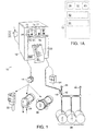
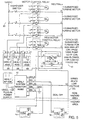
- a vapor recovery system monitoring system 10 of the invention includes a vapor recovery system monitor 12, a pressure-sensing switch 14, a signal relay 16, and a vent sensor 18.
- the basic functions to be monitored by the vapor recovery system monitoring system 10 of the invention include: vacuum level (for proper vapor recovery) and vent activity.
- the vacuum level is detected by pressure-sensing switch 14, which is adjusted to provide switch closure at the predetermined minimum vacuum level required for acceptable vapor recovery efficiency.
- the operating parameters measured include: time of vacuum motor operation, the maximum allowable time from vacuum motor start-up to switch closure at minimum vacuum level, and time at (or above) minimum operating vacuum level.
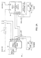
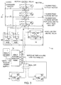
- an elementary wiring diagram 20 shows the connections required for electrical indication of vacuum motor operation from signal relay 16 (e.g., a Healy CB-1 signal relay, from Healy Systems, Inc. of Hudson, New Hampshire) and indication of vacuum level from the pressure-sensing or differential pressure switch 14 (e.g. a Healy 93928 low voltage pressure sensor, also from Healy Systems, Inc.)
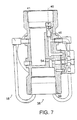
- the "vacuum on" signal relay 16 provides a switch closure when the vacuum source motor (e.g. minijet 22, vane pump 24 or blower 26; Fig.
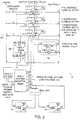
- the motor run time is accumulated in a first timer 28 of the microprocessor memory 30 of the vapor recovery system monitor 12.
- This switch closure also starts a second timer 32 to measure the time required to reach the minimum vacuum level, e.g. 10 seconds. If the minimum vacuum level of -1.65 m (-65 inches) WC is not achieved in 10 seconds (or less) on three consecutive vacuum motor start/stop cycles, a failure is recorded in the vapor recovery system monitor memory for printout 33 at the next scheduled reporting time. Also, a flashing red "LOW" vacuum light 34 is energized at the monitor 12 (Fig. 1) and an audible alarm is sounded to alert the service station attendant.
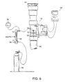
- the second major area of system monitoring is the vent activity for the underground fuel storage tanks 36 using the vent sensor 18 (e.g., a HEALY 6275 Vent Sensor, from Healy Systems, Inc.).
- the vent sensor 18 e.g., a HEALY 6275 Vent Sensor, from Healy Systems, Inc.
- the vent sensor 18 is designed to be mounted in a vertical orientation with 5.1 cm (2-inch) female tapered pipe thread connections 39, 41.
- the inlet 38 connects to the underground tank vent pipe 42 and the outlet 40 connects to a GARB-certified P/V valve 44.
- the present CARB California Air Resources Board
- a second higher pressure P/V valve 48 (Fig. 1) must be installed in parallel to provide protection for the underground tanks 36.
- the standards for the second P/V valve 48 are 225 gms (8 oz.) cracking pressure (+35.6 cm (14 inches) WC) and 20.3 cm (8 inches) cracking vacuum.
- a differential pressure gauge 59 (e.g., a Magnehelic Differential Pressure Gauge (0-25.4 cm (0-10 inches) WC), from Dwyer Instruments, Inc.) may optionally be employed to confirm the proper test flow pressure.
- the position of the pressure differential switch 62 is monitored with a DC volt meter (0-12 volts) 64.
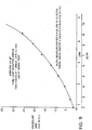
- the air flow range for the measuring orifice 46 on the vent sensor 18 is, e.g., from 1.0 lpm (1 ⁇ 4 gpm) to 3.8 lpm (1 gpm) using the pressure differential switch 62.
- Other vent flow ranges can be easily accommodated by changing the diameter of the measuring orifice 46, e.g. as shown in the "Air Flow Versus ⁇ P" graph of Fig. 9.
- the invention provides a simple, cost effective vapor recovery system monitoring system for detection of the failures outlined above, which cause reductions in vapor recovery efficiency in the gasoline station environment.
- the vent sensor 18 employs a simple orifice 46 to create a small pressure differential whenever the volume of vent emissions exceeds 1.9 lpm (1 ⁇ 2 gpm).
- the sensor is mounted in series with a CARB-certified pressure vacuum vent valve 44 to comply with the current California Stage II vapor recovery system regulations.
- the pressure differential switch 62 will close, providing continuity between wire #13 and wire #14.
- a second memory register 30A also accumulates vent time over a 24-hour period. If the venting time exceeds 10 hours within a 24-hour day on three consecutive days, a failure is recorded in memory for printout 33 at the next scheduled reporting time. Also, a flashing red "EXCESS" venting light 66 is energized at the monitor 12 (Fig. 1) , and an audible alarm is sounded to alert the service station attendant.
- the selection of 1.9 lpm (4 SCFH (1 ⁇ 2 gpm)) as the leak rate is based on a typical service station with gasoline sales of 384,600 liters (100,000 gallons) per month.
- the excess venting parameter is set at 10 hours within a 24 hour time frame. Venting of 1.9 lpm (1 ⁇ 2 gpm) for 10 hours (600 minutes) results in a 1,155 liter (300 gallon) volume of vent emissions. This represents 10% of the approximately 11,550 liter (3,000 gallon) daily throughput and, therefore, exceeds the 5% loss allowed by CARB for Stage II vapor recovery systems.
- Service stations with smaller or larger monthly sales can be provided with a vent sensor adjustment approximating 10% of their specific sales level.
- the vapor recovery system monitoring system provides the service station owner with timely indication of the need for system maintenance while creating a permanent record of system performance for the responsible environmental enforcement agency.
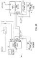
- solid state relays 68 e.g. Healy 1005W or Healy #939, from Healy Systems, Inc.
- solid state relays 68 will accept isolated signals from the output side (T2) terminal of each submerged turbine pump motor control relay 70. It is vital that all voltages referred to herein are on the same phase.
- the contact 68 closes, voltage is applied simultaneously to the motor control relay for the vacuum source (22, 24, 26) and a small mechanical relay 16 to provide a switch closure signal to the monitor 12 (the amber "MOTOR" light 72 and the flashing red “LOW” light 34 will illuminate).
- This signal also starts a non-resettable elapsed time recorder 28 that accumulates the total time the vacuum source has been activated.
- the monitor also provides a DC-sensing circuit across the normally-open contacts of the vacuum differential pressure switch 14, which is set to toggle from normally-open to normally-closed at 1.65 m (65 inch) water column (WC) vacuum.
- the pressure differential switch 14 will close at -65 inches WC, de-energizing the flashing red LED 34 and energizing the green "RUN" LED light 74 and a second elapsed-time meter 32 (non-reset) to record the total accumulated time at vacuum levels in excess of -1.65 m (-65 inches) WC.
- the low vacuum alarm (horn) is driven by the 5 VDC of the main control board 12.
- the "VACUUM RESET” button 76 will override the audible alarm until the next daily printout occurs.
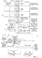
- the second major area of system monitoring is for detecting excessive vent emissions from the underground storage tanks 36. This is the loss of hydrocarbon vapors through the tank vent whenever the ullage space pressure exceeds the +7.6 cm ( ⁇ 1.3 cm) (+3 inches WC ( ⁇ 1 ⁇ 2 inch)) setting of a CARB-certified pressure vacuum vent valve 44, or at lower pressure, depending on the tightness and reliability of the vent valve.
- the vent sensor 18 of the vapor recovery system monitoring system of the invention is a fixed orifice bleed.
- a differential pressure switch 62 connected across the orifice is set at the CARB-specified leak rate. For example, a flow rate of approximately 1.9 lpm (0.5 gpm) of gasoline vapor will create a differential pressure of 1.0 cm (0.4 inch) WC, causing switch transfer.
- the two-wire connection to the switch on the vent riser is low voltage DC (standard) or intrinsically safe, if required, e.g. a Zener barrier, Model 111950 (from IMO Industries, Inc. of Lawrenceville, New Jersey) is UL recognized for this hazardous environment.
- a switch closure occurs which is detected by the system monitor 12 through the Zener barrier 84 which provides intrinsically safe protection for wires 15, 16. This will energize an amber "VENT" LED light 77 at the monitor 12 (Fig. 1) and a third elapsed-time meter 80 (non-reset) to record the total accumulated time when vent flow is occurring at or above the CARB-specified leak rate.
- the maximum vent time is preset at the factory at 10 hours.
- the field reporting procedure consists of daily printouts 33 from the system monitor 12. These printouts include all operating parameters including operating time and percentages for all the important data.
- the "PRINT DATA" button 82 is used to generate a current status report of the daily printout, information as shown in the following sample report.
- a failure history report showing the type of failure, date and time can be printed out by simultaneously pressing both "RESET" buttons 76, 78. The report will show the last 10 failures as shown in the following sample.
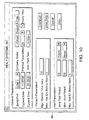
- the monitoring parameters as listed below and shown on the sample display 88 (Fig. 10) can be customized for each individual application using a support program.
- the download parameters and their effect on the vapor recovery system monitoring system of the invention are as follows:
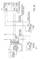
- the system may employ a pressure differential transmitter (e.g., a Dwyer Model 603A-12 pressure transmitter, from Dwyer Instruments, Inc.) in place of the single set point flow switch(es).
- a pressure differential transmitter e.g., a Dwyer Model 603A-12 pressure transmitter, from Dwyer Instruments, Inc.
- the output signal from the transmitter would indicate the vapor flow rate and, using the timing features and math powers of the microprocessor, the printout would show volume of flow as well as average flow rate.
- an intrinsically safe Zener barrier 84 e.g. HEALY Part No. 6299 Intrinsically Safe Assembly, from Healy Systems, Inc.
- wiring 86 as shown, e.g., in Figs. 2A, 3A, 4A and 5A.
- a second switch closure resulting from an orifice pressure differential in the opposite direction may be provided. Rising barometric pressure or vapor/liquid ratios set too low could cause this type of system failure.
- the same "EXCESS" venting flashing light 66 and audible alarm sounding would occur; however, the report 33 would indicate air inflow excess. Two additional wires to the vent sensor 18 would be required to provide this capability.
Landscapes
- Engineering & Computer Science (AREA)
- Mechanical Engineering (AREA)
- Loading And Unloading Of Fuel Tanks Or Ships (AREA)
- Examining Or Testing Airtightness (AREA)
Claims (10)
- Système de contrôle de système de récupération de vapeur (10) comprenant :un ensemble de contrôle de vide (12) comportant :un relais de signal de source de vide (16) en communication avec un système de vide desservi par une source de vide (22, 24, 26) et adapté pour générer un premier signal de vide lors de l'actionnement de la source de vide pour la récupération d'une vapeur de carburant déplacée et un deuxième signal de vide lorsqu'un niveau de vide minimal prédéterminé est atteint dans le système de vide ;un minuteur (32) pour mesurer le temps écoulé entre ledit premier signal de vide et ledit deuxième signal de vide ;un comparateur de vide (30) pour comparer le temps écoulé à une norme prédéterminée ; etun dispositif de signal de vide (33, 34) pour déclencher et/ou afficher un message d'erreur de vide après un nombre prédéterminé de cas où le temps écoulé dépasse la norme prédéterminée ; etun ensemble de détecteur d'évacuation comportant :un détecteur d'évacuation - (18) monté en communication avec un conduit d'évacuation (42) pour un réservoir de stockage souterrain (36), ou sur celui-ci, ledit détecteur d'évacuation définissant un orifice (46) adapté pour créer un différentiel de pression lorsque l'écoulement volumique des émissions d'évacuation dépasse un niveau prédéterminé ;un détecteur ou commutateur de différentiel de pression (14) ;un compteur (30) adapté pour recevoir un signal d'évacuation depuis ledit commutateur de différentiel de pression afin de délivrer une indication de la fréquence d'évacuation au cours d'une période de temps prédéterminée ;un minuteur (80) adapté pour recevoir un signal d'évacuation depuis ledit détecteur ou commutateur de différentiel de pression afin de délivrer une indication du temps d'évacuation total au cours d'une période de temps prédéterminée ;des moyens formant comparateur d'évacuation (30) pour comparer le temps d'évacuation total à un temps d'évacuation total acceptable prédéterminé ; etun dispositif de signal d'évacuation (33, 66) pour déclencher ou afficher un message d'erreur d'évacuation, lorsqu'un temps d'évacuation total acceptable prédéterminé est dépassé.
- Système de contrôle de système de récupération de vapeur selon la revendication 1, dans lequel ledit niveau de vide minimal prédéterminé pour la délivrance dudit deuxième signal de vide est d'environ - 1,65 m (-65 pouces) à la colonne d'eau.
- Système de contrôle de système de récupération de vapeur selon la revendication 1, dans lequel ledit dispositif de signal de vide affiche le message d'erreur de vide après un nombre prédéterminé de cas consécutifs où le temps écoulé dépasse la norme prédéterminée et/ou ledit dispositif de signal d'évacuation affiche le message d'erreur d'évacuation après un nombre prédéterminé de jours consécutifs où le temps d'évacuation total dépasse le temps d'évacuation total acceptable prédéterminé.
- Système de contrôle de système de récupération de vapeur selon la revendication 1, comprenant de plus un deuxième détecteur d'évacuation monté en communication avec un conduit d'évacuation pour un réservoir de stockage souterrain ou sur celui-ci pour la détection d'ingestion d'air dans le réservoir de stockage, ledit deuxième détecteur d'évacuation définissant un orifice pour créer un différentiel de pression- à chaque fois que le volume d'ingestion d'évacuation dépasse un niveau prédéterminé,
ledit deuxième détecteur d'évacuation comportant :un deuxième détecteur ou commutateur de différentiel de pression ;un compteur adapté pour recevoir un signal d'ingestion d'évacuation depuis ledit deuxième détecteur ou commutateur de différentiel de pression afin de délivrer une indication de fréquence d'ingestion d'évacuation au cours d'une période de temps prédéterminée ;un minuteur adapté pour recevoir un signal d'ingestion d'évacuation depuis ledit deuxième détecteur ou commutateur de différentiel de pression afin de délivrer une indication du temps d'ingestion d'évacuation total au cours d'une période de temps prédéterminée ;un comparateur d'ingestion d'évacuation pour comparer le temps d'ingestion d'évacuation total à un temps d'ingestion d'évacuation total acceptable prédéterminé ; etun dispositif de signal d'ingestion d'évacuation pour déclencher ou afficher un message d'erreur d'ingestion d'évacuation lorsqu'un temps d'ingestion d'évacuation total acceptable prédéterminé est dépassé. - Système de contrôle de système de récupération de vapeur selon la revendication 4, dans lequel ledit dispositif de signal d'ingestion d'évacuation est adapté pour afficher le message d'erreur d'ingestion d'évacuation après un nombre prédéterminé de jours consécutifs où le temps d'ingestion d'évacuation total dépasse le temps d'ingestion d'évacuation total acceptable prédéterminé.
- Système de contrôle de système de récupération de vapeur selon la revendication 1 ou 4, dans lequel ledit ensemble de détecteur d'évacuation comprend un transmetteur de différentiel de pression pour le-calcul du volume évacué et/ou pour le calcul du volume ingéré.
- Procédé pour contrôler un système de récupération de vapeur, ledit procédé comprenant les étapes suivantes :la disposition d'un ensemble de contrôle de vide (10) comportant un dispositif de signal de source de vide (16) en communication avec un système de vide desservi par une source de vide (22, 24, 26) ;le fait de faire générer par le dispositif de signal de source de vide un premier signal de vide lors de l'actionnement de la source de vide pour la-récupération de vapeur de carburant déplacée ;le fait de faire générer par le dispositif de signal de source de vide un deuxième signal de vide lorsqu'un niveau de vide minimal prédéterminé est atteint dans le système de vide ;la mesure du temps écoulé entre le premier signal de vide et le deuxième signal de vide ;la comparaison du temps écoulé à une norme prédéterminée ; etla génération d'un message d'erreur de vide après un nombre prédéterminé de cas où le temps écoulé dépasse la norme prédéterminée ;la disposition d'un ensemble de détecteur d'évacuation comportant un détecteur d'évacuation (18) en communication avec un conduit d'évacuation (42) venant d'un réservoir de stockage souterrain (36), le détecteur d'évacuation définissant un orifice (46) adapté pour créer un différentiel de pression lorsque l'écoulement volumique de l'émission d'évacuation dépasse un niveau prédéterminé, et un détecteur de différentiel de pression ;le fait de faire délivrer par le détecteur de différentiel de pression un signal d'évacuation à un compteur afin de délivrer une indication de la fréquence d'évacuation au cours d'une période de temps prédéterminée ;le fait de faire délivrer par un détecteur de différentiel de pression un signal d'évacuation à un minuteur afin de délivrer une indication de temps d'évacuation total au cours d'une période de temps prédéterminée ;la comparaison du temps d'évacuation total à un temps d'évacuation total acceptable prédéterminé ; etla génération d'un message d'erreur d'évacuation lorsqu'un temps d'évacuation total acceptable prédéterminé est dépassé.
- Procédé pour contrôler un système de récupération de vapeur selon la revendication 7, ledit procédé comprenant l'étape supplémentaire de génération du message d'erreur de vide après un nombre prédéterminé de cas consécutifs où le temps écoulé dépasse la norme prédéterminée, et/ou de génération du message d'erreur d'évacuation après un nombre prédéterminé de jours consécutifs où le temps d'évacuation total dépasse le temps d'évacuation total acceptable prédéterminé.
- Procédé pour contrôler un système de récupération de vapeur selon la revendication 7, ledit procédé comprenant l'étape supplémentaire de disposition d'un deuxième détecteur d'évacuation en communication avec un conduit d'évacuation pour un réservoir de stockage souterrain pour la détection d'ingestion d'air dans le réservoir de stockage, le deuxième détecteur d'évacuation définissant un orifice pour créer un différentiel de pression à chaque fois que le volume d'ingestion d'évacuation dépasse un niveau prédéterminé, et d'un deuxième détecteur de différentiel de pression ;le fait de faire délivrer par le deuxième détecteur de différentiel de pression un signal d'ingestion d'évacuation à un compteur afin de délivrer une indication de fréquence d'ingestion d'évacuation au cours d'une période de temps prédéterminée ;le fait de faire délivrer par le- deuxième commutateur de différentiel de pression un signal d'ingestion d'évacuation à un minuteur afin de délivrer une indication de temps d'ingestion d'évacuation total au cours d'une période de temps prédéterminée ;la comparaison du temps d'ingestion d'évacuation total à un temps d'ingestion d'évacuation total acceptable prédéterminé ; etla génération d'un message d'erreur d'ingestion d'évacuation lorsqu'un temps d'ingestion d'évacuation total acceptable prédéterminé est dépassé.
- Procédé pour contrôler un système de récupération de vapeur selon la revendication 9, ledit procédé comprenant l'étape supplémentaire de génération du message d'erreur d'ingestion d'évacuation après un nombre prédéterminé de jours consécutifs où le temps d'ingestion d'évacuation total dépasse le temps d'ingestion d'évacuation total acceptable prédéterminé.
Applications Claiming Priority (3)
| Application Number | Priority Date | Filing Date | Title |
|---|---|---|---|
| US08/818,259 US5765603A (en) | 1997-03-14 | 1997-03-14 | Monitoring fuel vapor flow in vapor recovery system |
| US818259 | 1997-03-14 | ||
| PCT/US1998/002320 WO1998041470A1 (fr) | 1997-03-14 | 1998-02-25 | Surveillance des flux de vapeur d'un systeme de recuperation de vapeurs de carburant |
Publications (2)
| Publication Number | Publication Date |
|---|---|
| EP0966397A1 EP0966397A1 (fr) | 1999-12-29 |
| EP0966397B1 true EP0966397B1 (fr) | 2001-04-11 |
Family
ID=25225085
Family Applications (1)
| Application Number | Title | Priority Date | Filing Date |
|---|---|---|---|
| EP19980906193 Expired - Lifetime EP0966397B1 (fr) | 1997-03-14 | 1998-02-25 | Procédé et dispositif de surveillance d'un système de récupération de vapeurs de carburant |
Country Status (5)
| Country | Link |
|---|---|
| US (1) | US5765603A (fr) |
| EP (1) | EP0966397B1 (fr) |
| AU (1) | AU6147998A (fr) |
| DE (1) | DE69800696T2 (fr) |
| WO (1) | WO1998041470A1 (fr) |
Families Citing this family (20)
| Publication number | Priority date | Publication date | Assignee | Title |
|---|---|---|---|---|
| WO1999043986A1 (fr) * | 1998-02-26 | 1999-09-02 | Robert Bradt | Appareil de regulation des emissions de vapeur d'essence |
| AU752463B2 (en) * | 1998-08-25 | 2002-09-19 | Marconi Commerce Systems Inc. | Fuel delivery system |
| US6176275B1 (en) | 1999-02-03 | 2001-01-23 | Bob J. Hill | Vapor recovery system for mobile fuelers |
| US6167923B1 (en) | 1999-09-01 | 2001-01-02 | Marconi Commerce Systems Inc. | Vapor recovery diagnostics |
| US6712101B1 (en) | 1999-11-17 | 2004-03-30 | Gilbarco Inc. | Hydrocarbon sensor diagnostic method |
| US6460579B2 (en) | 1999-11-17 | 2002-10-08 | Gilbarco Inc. | Vapor flow and hydrocarbon concentration sensor for improved vapor recovery in fuel dispensers |
| US6418983B1 (en) | 1999-11-17 | 2002-07-16 | Gilbasco Inc. | Vapor flow and hydrocarbon concentration sensor for improved vapor recovery in fuel dispensers |
| US6386246B2 (en) | 1999-11-17 | 2002-05-14 | Marconi Commerce Systems Inc. | Vapor flow and hydrocarbon concentration sensor for improved vapor recovery in fuel dispensers |
| WO2003076329A1 (fr) * | 2002-03-05 | 2003-09-18 | Veeder-Root Company Inc. | Dispositif et procede de controle de surpression dans un systeme de stockage de carburant d'une installation de distribution de carburant |
| US6948536B1 (en) | 2002-12-27 | 2005-09-27 | Hirt Combustion Engineers, Inc. | System for detecting liquid fuel blockages in the vapor return line of a fuel dispenser |
| US6810922B1 (en) | 2003-10-10 | 2004-11-02 | Vapor Systems Technologies, Inc. | Vapor recovery system with improved ORVR compatibility and performance |
| US7509982B2 (en) * | 2003-10-10 | 2009-03-31 | Vapor Systems Technologies, Inc. | Vapor recovery system with improved ORVR compatibility and performance |
| US6923221B2 (en) * | 2003-12-04 | 2005-08-02 | Gilbarco Inc. | Vapor recovery system with ORVR compensation |
| US8167003B1 (en) | 2008-08-19 | 2012-05-01 | Delaware Capital Formation, Inc. | ORVR compatible refueling system |
| US8371341B2 (en) * | 2009-09-24 | 2013-02-12 | Deleware Capital Formation, Inc. | Magnetically actuated vapor recovery valve |
| IT1398742B1 (it) * | 2010-03-12 | 2013-03-18 | Piusi Spa | Pistola automatica erogatrice di liquido. |
| US9604837B2 (en) | 2012-01-06 | 2017-03-28 | Husky Corporation | ORVR valve assembly |
| US9376989B2 (en) | 2013-07-17 | 2016-06-28 | Ford Global Technologies, Llc | Fuel tank pressure relief valve cleaning |
| US11524888B1 (en) | 2022-07-26 | 2022-12-13 | Bob J. Hill | Vapor recovery system for mobile fuelers |
| US12152736B2 (en) * | 2023-01-12 | 2024-11-26 | Air Products And Chemicals, Inc. | System and method for compressed gas dispensing with subsequent venting |
Family Cites Families (22)
| Publication number | Priority date | Publication date | Assignee | Title |
|---|---|---|---|---|
| JPS5810098Y2 (ja) * | 1973-05-07 | 1983-02-24 | 株式会社小松製作所 | ユアツソクテイソウチ |
| US3926230A (en) * | 1974-06-12 | 1975-12-16 | Marvin L Stary | Recovery of flammable vapors |
| US3983913A (en) * | 1975-06-03 | 1976-10-05 | Emco Wheaton Inc. | Vapor recovery and vent signal system |
| US4100758A (en) * | 1976-11-19 | 1978-07-18 | Texaco Inc. | Vacuum assist fuel system |
| US4072934A (en) * | 1977-01-19 | 1978-02-07 | Wylain, Inc. | Method and apparatus for detecting a blockage in a vapor flow line |
| US4197883A (en) * | 1978-01-16 | 1980-04-15 | Texaco Inc. | Secondary fuel recovery system |
| IT1228284B (it) * | 1989-01-04 | 1991-06-07 | Nuovo Pignone Spa | Sistema perfezionato per un sicuro recupero vapori, particolarmente adatto per impianti di distribuzione carburanti |
| US5156199A (en) * | 1990-12-11 | 1992-10-20 | Gilbarco, Inc. | Control system for temperature compensated vapor recovery in gasoline dispenser |
| US5429159A (en) * | 1991-08-02 | 1995-07-04 | Fina Technology, Inc. | Vapor recovery system for vehicle loading operation |
| US5275144A (en) * | 1991-08-12 | 1994-01-04 | General Motors Corporation | Evaporative emission system diagnostic |
| US5146902A (en) * | 1991-12-02 | 1992-09-15 | Siemens Automotive Limited | Positive pressure canister purge system integrity confirmation |
| WO1993017955A1 (fr) * | 1992-03-08 | 1993-09-16 | Fritz Curtius | Traitement des vapeurs d'essence dans les stations-service |
| US5269353A (en) * | 1992-10-29 | 1993-12-14 | Gilbarco, Inc. | Vapor pump control |
| US5345979A (en) * | 1992-10-29 | 1994-09-13 | Gilbacro, Inc. | High efficiency vapor recovery fuel dispensing |
| US5411004A (en) * | 1993-02-03 | 1995-05-02 | Siemens Automotive Limited | Positive pressure canister purge system integrity confirmation |
| US5332008A (en) * | 1993-02-04 | 1994-07-26 | Dresser Industries, Inc. | Gasoline dispenser with enhanced vapor recovery system |
| ATE161798T1 (de) * | 1993-03-09 | 1998-01-15 | Technology Trading Bv | Automatische, lecksichere betankungsvorrichtung |
| US5305807A (en) * | 1993-04-22 | 1994-04-26 | Healy Systems, Inc. | Auxiliary vapor recovery device for fuel dispensing system |
| US5316057A (en) * | 1993-04-28 | 1994-05-31 | Hasselmann Detlev E M | Vapor recovery system tester |
| US5417256A (en) * | 1993-10-04 | 1995-05-23 | Gilbarco, Inc. | Centralized vacuum assist vapor recovery system |
| US5450883A (en) * | 1994-02-07 | 1995-09-19 | Gilbarco, Inc. | System and method for testing for error conditions in a fuel vapor recovery system |
| DE4434216C2 (de) * | 1994-03-19 | 1998-04-09 | Fritz Curtius | Verfahren zur Diagnose von Kraftstoffleckagen |
-
1997
- 1997-03-14 US US08/818,259 patent/US5765603A/en not_active Expired - Lifetime
-
1998
- 1998-02-25 EP EP19980906193 patent/EP0966397B1/fr not_active Expired - Lifetime
- 1998-02-25 WO PCT/US1998/002320 patent/WO1998041470A1/fr not_active Ceased
- 1998-02-25 AU AU61479/98A patent/AU6147998A/en not_active Abandoned
- 1998-02-25 DE DE69800696T patent/DE69800696T2/de not_active Expired - Fee Related
Also Published As
| Publication number | Publication date |
|---|---|
| DE69800696T2 (de) | 2001-09-06 |
| AU6147998A (en) | 1998-10-12 |
| US5765603A (en) | 1998-06-16 |
| WO1998041470A1 (fr) | 1998-09-24 |
| DE69800696D1 (de) | 2001-05-17 |
| EP0966397A1 (fr) | 1999-12-29 |
Similar Documents
| Publication | Publication Date | Title |
|---|---|---|
| EP0966397B1 (fr) | Procédé et dispositif de surveillance d'un système de récupération de vapeurs de carburant | |
| AU752463B2 (en) | Fuel delivery system | |
| US20020188382A1 (en) | Method and apparatus for monitoring and controlling pump and valve system operations | |
| US5384714A (en) | Pump controller program | |
| US5400253A (en) | Automated statistical inventory reconcilation system for convenience stores and auto/truck service stations | |
| US5857500A (en) | System and method for testing for error conditions in a fuel vapor recovery system | |
| US8291928B2 (en) | Vacuum-actuated shear valve device, system, and method, particularly for use in service station environments | |
| JP5468050B2 (ja) | 自己モニター式インテリジェント噴流デイスペンサー | |
| EP3436398B1 (fr) | Ensemble de capteur de distribution de carburant | |
| US20120158192A1 (en) | Apparatus for Monitoring and Controlling Material Handling System Operations | |
| EP1509451A1 (fr) | Procede et systeme pour empecher le meremplissage d'un vehicule | |
| EP1101729A1 (fr) | Dispositif et méthode pour la diagnose de la performance d'un système de récupération de vapeurs | |
| US6953046B2 (en) | Microprocessor-based gas meter | |
| US4496077A (en) | Leak detector monitor for pressurized flow systems | |
| US7575015B2 (en) | Secondarily contained in-dispenser sump/pan system and method for capturing and monitoring leaks | |
| US5375454A (en) | Programmable pump controller | |
| US5325312A (en) | Intelligent pressure probe | |
| US5900811A (en) | Method and apparatus for assuring maintenance of vehicle components | |
| US6788209B2 (en) | Automatic emergency shut-off system for delivery transports | |
| WO2000055047A1 (fr) | Systeme de recuperation des vapeurs et procede comprenant la detection de fuites et de flux d'air | |
| US6421616B1 (en) | Fraud detection through inference | |
| JP3343321B2 (ja) | 給油機 | |
| JP3175412B2 (ja) | 燃料計量装置 | |
| US3735897A (en) | Self service dispensing remote control system | |
| JPS6346397Y2 (fr) |
Legal Events
| Date | Code | Title | Description |
|---|---|---|---|
| PUAI | Public reference made under article 153(3) epc to a published international application that has entered the european phase |
Free format text: ORIGINAL CODE: 0009012 |
|
| 17P | Request for examination filed |
Effective date: 19990909 |
|
| AK | Designated contracting states |
Kind code of ref document: A1 Designated state(s): DE FR GB IT |
|
| 17Q | First examination report despatched |
Effective date: 20000228 |
|
| GRAG | Despatch of communication of intention to grant |
Free format text: ORIGINAL CODE: EPIDOS AGRA |
|
| GRAG | Despatch of communication of intention to grant |
Free format text: ORIGINAL CODE: EPIDOS AGRA |
|
| GRAH | Despatch of communication of intention to grant a patent |
Free format text: ORIGINAL CODE: EPIDOS IGRA |
|
| GRAH | Despatch of communication of intention to grant a patent |
Free format text: ORIGINAL CODE: EPIDOS IGRA |
|
| GRAA | (expected) grant |
Free format text: ORIGINAL CODE: 0009210 |
|
| AK | Designated contracting states |
Kind code of ref document: B1 Designated state(s): DE FR GB IT |
|
| REF | Corresponds to: |
Ref document number: 69800696 Country of ref document: DE Date of ref document: 20010517 |
|
| ET | Fr: translation filed | ||
| ITF | It: translation for a ep patent filed | ||
| REG | Reference to a national code |
Ref country code: GB Ref legal event code: IF02 |
|
| PLBE | No opposition filed within time limit |
Free format text: ORIGINAL CODE: 0009261 |
|
| STAA | Information on the status of an ep patent application or granted ep patent |
Free format text: STATUS: NO OPPOSITION FILED WITHIN TIME LIMIT |
|
| 26N | No opposition filed | ||
| PGFP | Annual fee paid to national office [announced via postgrant information from national office to epo] |
Ref country code: GB Payment date: 20040218 Year of fee payment: 7 |
|
| PGFP | Annual fee paid to national office [announced via postgrant information from national office to epo] |
Ref country code: FR Payment date: 20040219 Year of fee payment: 7 |
|
| PGFP | Annual fee paid to national office [announced via postgrant information from national office to epo] |
Ref country code: DE Payment date: 20040331 Year of fee payment: 7 |
|
| PG25 | Lapsed in a contracting state [announced via postgrant information from national office to epo] |
Ref country code: IT Free format text: LAPSE BECAUSE OF NON-PAYMENT OF DUE FEES Effective date: 20050225 Ref country code: GB Free format text: LAPSE BECAUSE OF NON-PAYMENT OF DUE FEES Effective date: 20050225 |
|
| PG25 | Lapsed in a contracting state [announced via postgrant information from national office to epo] |
Ref country code: DE Free format text: LAPSE BECAUSE OF NON-PAYMENT OF DUE FEES Effective date: 20050901 |
|
| GBPC | Gb: european patent ceased through non-payment of renewal fee |
Effective date: 20050225 |
|
| PG25 | Lapsed in a contracting state [announced via postgrant information from national office to epo] |
Ref country code: FR Free format text: LAPSE BECAUSE OF NON-PAYMENT OF DUE FEES Effective date: 20051031 |
|
| REG | Reference to a national code |
Ref country code: FR Ref legal event code: ST Effective date: 20051031 |