EP0966089A2 - Verfahren und Vorrichtung zur Ladung von Batterien - Google Patents
Verfahren und Vorrichtung zur Ladung von Batterien Download PDFInfo
- Publication number
- EP0966089A2 EP0966089A2 EP99304741A EP99304741A EP0966089A2 EP 0966089 A2 EP0966089 A2 EP 0966089A2 EP 99304741 A EP99304741 A EP 99304741A EP 99304741 A EP99304741 A EP 99304741A EP 0966089 A2 EP0966089 A2 EP 0966089A2
- Authority
- EP
- European Patent Office
- Prior art keywords
- temperature
- battery
- change rate
- temperature change
- predetermined threshold
- Prior art date
- Legal status (The legal status is an assumption and is not a legal conclusion. Google has not performed a legal analysis and makes no representation as to the accuracy of the status listed.)
- Withdrawn
Links
Images



Classifications
-
- H—ELECTRICITY
- H02—GENERATION; CONVERSION OR DISTRIBUTION OF ELECTRIC POWER
- H02J—ELECTRIC POWER NETWORKS; CIRCUIT ARRANGEMENTS OR SYSTEMS FOR SUPPLYING OR DISTRIBUTING ELECTRIC POWER; SYSTEMS FOR STORING ELECTRIC ENERGY
- H02J7/00—Circuit arrangements for charging or discharging batteries or for supplying loads from batteries
- H02J7/90—Regulation of charging or discharging current or voltage
- H02J7/971—Regulation of charging or discharging current or voltage the charge cycle being controlled or terminated in response to non-electric parameters
- H02J7/975—Regulation of charging or discharging current or voltage the charge cycle being controlled or terminated in response to non-electric parameters in response to temperature
- H02J7/977—Regulation of charging or discharging current or voltage the charge cycle being controlled or terminated in response to non-electric parameters in response to temperature of the battery
Definitions
- This invention relates generally to a method and apparatus for charging rechargeable batteries.
- cordless power for portable power tools and certain kitchen and domestic appliances have led to the development of a wide range of sizes of power- or battery-packs, that is, a contained group of power cells.
- These power cells may include nickel cadmium (NiCd), nickel metal hydride (NiMH), lithium, or lead-acid cells, etc.
- the battery temperature and voltage vary. For example, battery temperature increases in a nonlinear manner as the battery is charged. The battery temperature then quickly increases as the battery becomes fully charged. However, if the charging process is not stopped when the battery is fully charged, the battery could be overcharged and thus damaged by the rising temperature. Accordingly, battery temperature or battery voltage are usually monitored as indicators of the full charge condition.
- the Saar double inflection termination method described in U.S. Patent Nos. 4,388,582 and 4,392,101 is preferred to detect a battery reaching full charge.
- Other voltage monitoring methods more typically employed are (1) the minus-delta-voltage method, (2) the peak detect method, and (3) the voltage slope detect method.
- the minus-delta-voltage method a sample of the battery peak voltage is stored and compared to the most recent voltage. Termination occurs when the most recent voltage falls below a set point, usually within between 0.5% and 1.0% of the stored peak, or about 10 to 20 millivolts per cell for a NiCd battery.
- the peak detect method is more modern version of the minus-delta-voltage method. Basically, the same method is used, except the set point can be set closer to the peak by using more accurate instrumentation.
- the slope detect method is another voltage monitoring method. According to this method, the voltage peak B is detected by calculating the slope of the voltage curve V, or voltage change rate (dV/dt). Termination occurs when the voltage change rate is 0 or negative.
- Temperature monitoring methods typically employed are (1) absolute temperature termination and (2) temperature change rate termination.
- Absolute temperature termination relies on the temperature rise that occurs when the battery is fully charged. Under this method, the charging process will be stopped when the battery temperature reaches a certain temperature.
- the temperature change rate termination method requires monitoring the changing slope of the battery temperature, or temperature change rate (dT/dt), during the charging process. Termination occurs when the temperature change rate reaches and/or exceeds a predetermined rate. In other words, termination occurs when a trip point is reached and/or exceeded. However, selecting the appropriate trip point is problematic, especially under conditions of varying ambient temperature conditions. Accordingly, the method may cause undercharged batteries.
- a method for charging a rechargeable battery pack includes providing a current to the battery pack, sensing battery temperature, determining temperature change rate, and disabling termination of the charging method based on a temperature-based scheme if the temperature change rate exceeds a first predetermined threshold within a first predetermined period of time. Termination of the charging method based on a temperature-based scheme may be re-enabled if the temperature change rate is less than a second predetermined threshold. Preferably the second predetermined threshold is equal to the first predetermined threshold. Alternatively, termination of the charging method based on a temperature-based scheme may be re-enabled after a second predetermined period of time has elapsed.
- a battery charging method comprising providing a current to the battery pack, sensing battery temperature, determining temperature change rate, and suspending the current if the temperature change rate exceeds a first predetermined threshold within a first predetermined period of time.
- Current will be re-sent if the temperature change rate is less than a second predetermined threshold.
- the second predetermined threshold is equal to the first predetermined threshold.
- current will be re-sent after a second predetermined period of time has elapsed.
- a battery 10 is connected to a charger control circuit 20.
- Battery 10 comprises a plurality of battery cells 11 connected in series, which dictate the voltage and storage capacity for battery 10.
- Battery 10 includes three battery contacts: first battery contact 12, second battery contact 13, and third battery contact 14.
- Battery contact 12 is the B+ (positive) terminal for battery 10.
- Battery contact 13 is the B- or negative/common terminal.
- Battery contact 14 is the S or sensing terminal.
- Battery contacts 12 and 13 receive the charging current sent from the charger control circuit 20 (preferably from current source 22, as discussed below)for charging the battery 10.
- the battery cells 11 are coupled between the battery contacts 12 and 13.
- a temperature sensing device 15 such as a negative temperature co-efficient (NTC) resistor, or thermistor, R T .
- NTC negative temperature co-efficient
- the temperature sensing device is preferably in closer proximity to the cells 11 for monitoring of the battery temperature.
- other components such as capacitors, etc., or circuits can be used to provide a signal representative of the battery temperature.
- the charger control circuit 20 preferably comprises a controller 21, which in turn includes positive terminal (B+) 16 and negative (B-) terminal 17, which are coupled to battery 10 via battery contacts 12 and 13, respectively.
- the positive terminal may also act as an input, preferably an analog/digital input, in order for the controller 21 to detect the battery voltage.
- the controller 21 may include another input T, preferably an analog/digital input, which is coupled to the temperature sensing device 15 via the third battery contact 14 (S). This allows the controller 21 to monitor the battery temperature.
- Controller 21 includes a microprocessor 23 for controlling the charging and monitoring operations. Controller 21 may control a current source 22 that provides current to battery 10. This current may be a fast charging current and/or an equalization current. Current source 22 may be integrated within controller 21.
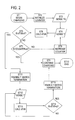
- FIG. 2 is a flowchart of the different steps comprised in a first embodiment of the proposed method.
- the first step (ST1) is to begin the charging process by sending current to battery 10.
- the controller 21 may initialize a counter (ST2).
- the controller 21, via its inputs, may sense the initial battery temperature T0 (ST3). Preferably, if the initial temperature T0 is above a certain threshold, the controller 21 will discontinue charging. The controller 21 may restart charging if the battery temperature falls below the threshold or after a predetermined period of time has elapsed. Preferably, charging will be suspended if the battery temperature is above about 45°C.
- steps ST2 and/or ST3 may be performed before the charging process is begun on step ST1.
- the controller 21 preferably continues to sense the battery temperature (ST4). In addition, the controller 21 calculates the temperature change rate, i.e., first derivative of temperature dT/dt (ST5). The controller 21 also determines whether the temperature change rate is above or below a predetermined threshold X (ST6).
- the predetermined threshold X for NiCd batteries is between about 0.7 and 2.0 Celsius degrees per minute, with the preferred threshold being about 1.2 Celsius degrees per minute.
- the controller 21 may then determine whether the counter is higher than or equal to a predetermined threshold A (ST7). If not, the counter is increased (ST8) and the controller 21 continues to sense the battery temperature (ST4). If the counter is higher than or equal to threshold A, the controller 21 then continues charging the battery (ST9) until termination occurs (ST10).
- the counter is used to determine whether the temperature change rate exceeds threshold X within a predetermined period of time. Accordingly, the counter may be replaced by a timer. Alternatively, the decreasing counter may be used instead of the increasing timer mentioned above. Again, the speed, frequency or orientation of the counter do not matter so long as it can delineate a predetermined period of time.
- the predetermined period of time may be less than 5 minutes long, preferably beginning at the start of the charging process. Preferably, the predetermined period of time is 2 minutes.
- the charging process cannot be terminated based on the absolute temperature and/or temperature change rate schemes explained above. Further, the charging process preferably cannot be terminated based on any other scheme that uses any type of temperature information, such as the double derivative of temperature scheme disclosed in U.S. Patent No. 5,519,303. Charging nevertheless may still be terminated at any time using voltage-based schemes as explained above.
- the controller 21 then preferably continues to sense the battery temperature (ST12), calculating the temperature change rate dT/dt (ST13), and determining whether the temperature change rate is above or below a predetermined threshold Y (ST14).
- the predetermined threshold Y is equal to the predetermined threshold X.
- the controller 21 may continue repeating these steps until the temperature change rate is below threshold Y, or until a predetermined period of time has elapsed. Once either condition is met, termination of the charging process based on temperature schemes is re-enabled (ST15). In other words, the charging process can now be terminated based on the absolute temperature, temperature change rate and/or double derivative of temperature schemes explained above. Charging of the battery then continues (ST9) until tennination (ST10).
- FIG. 3 is is flowchart of the different steps comprised in a second embodiment of the proposed method.
- the first step (ST16) is to begin the charging process by sending current to battery 10.
- the controller 21 may initialize a counter (ST17).
- the controller 21, via its inputs, may sense the initial battery temperature T0 (ST18). Preferably, if the initial temperature T0 is above a certain threshold, the controller 21 will discontinue charging. The controller 21 may restart charging if the battery temperature falls below the threshold or after a predetermined period of time has elapsed. Preferably, charging will be suspended if the battery temperature is above 45°C.
- steps ST17 and/or ST18 may be performed before the charging process is begun on step ST16.
- the controller 21 preferably continues to sense the battery temperature (ST19). In addition, the controller 21 calculates the temperature change rate, i.e., first derivative of temperature dT/dt (ST20). The controller 21 also determines whether the temperature change rate is above or below a predetermined threshold X (ST21).
- the predetermined threshold X for NiCd batteries is between about 0.7 and 2.0 Celsius degrees per minute, with the preferred threshold being about 1.2 Celsius degrees per minute.
- the controller 21 may then determine whether the counter is higher than or equal to a predetermined threshold A (ST22). If not, the counter is increased (ST23) and the controller 21 continues to sense the battery temperature (ST19). If the counter is higher than or equal to threshold A, the controller 21 then continues charging the battery (ST24) until termination occurs (ST25).
- the counter is used to determine whether the temperature change rate exceeds threshold X within a predetermined period of time. Accordingly, the counter may be replaced by a timer. Alternatively, the decreasing counter may be used instead of the increasing timer mentioned above. Again, the speed, frequency or orientation of the counter do not matter so long as it can determine whether the temperature change rate exceeds threshold X within a predetermined period of time.
- the predetermined period of time may be less than 5 minutes long, preferably beginning at the start of the charging process. Preferably, the predetermined period of time is 2 minutes.
- the charging process is suspended (ST26). In other words, current is not sent to battery 10.
- the controller 21 then preferably continues to sense the battery temperature (ST27), calculating the temperature change rate dT/dt (ST28), and determining whether the temperature change rate is above or below a predetermined threshold Y (ST29).
- the predetermined threshold Y is equal to the predetermined threshold X.
- the controller 21 may continue repeating these steps until the temperature change rate is below threshold Y, or until a predetermined period of time has elapsed. Once either condition is met, the charging process is restarted (ST30). In other words, current is re-sent to battery 10. Charging of the battery then continues (ST24) until termination (ST25).
- FIG. 4 is a flowchart of the different steps comprised in a third embodiment of the proposed method.
- the first step (ST31) is to disable termination of the charging process based on temperature schemes.
- the charging process cannot be terminated based on the absolute temperature and/or temperature change rate schemes explained above.
- the charging process preferably cannot be terminated based on any other scheme that uses any type of temperature information, such as the double derivative of temperature scheme disclosed in U.S. Patent No. 5,519,303. Charging nevertheless may still be terminated at any time using voltage-based schemes as explained above.
- the controller 21 may initialize a counter (ST32) and then begin the charging process by sending current to battery 10 (ST33).
- the controller 21, via its inputs, may sense the initial battery temperature T0 (ST34). Preferably, if the initial temperature T0 is above a certain threshold, the controller 21 will discontinue charging. The controller 21 may restart charging if the battery temperature falls below the threshold or after a predetermined period of time has elapsed. Preferably, charging will be suspended if the battery temperature is above about 45°C.
- steps ST31 through ST34 may be altered in any way or manner so desired.
- the controller 21 preferably continues to sense the battery temperature (ST35). In addition, the controller 21 calculates the temperature change rate, i.e., first derivative of temperature dT/dt (ST36). The controller 21 also determines whether the temperature change rate is above or below a predetermined threshold X (ST37).
- the predetermined threshold X for NiCd batteries is between about 0.7 and 2.0 Celsius degrees per minute, with the preferred threshold being about 1.2 Celsius degrees per minute.
- the controller 21 may then determine whether the counter is higher than or equal to a predetermined threshold A (ST38). If not, the counter is increased (ST39) and the controller 21 continues to sense the battery temperature (ST35). If the counter is higher than or equal to threshold A, temperature-based termination is re-enabled (ST40). In other words, the charging process can now be terminated based on the absolute temperature, temperature change rate and/or double derivative of temperature schemes explained above. Charging of the battery then continues (ST41) until termination (ST42).
- the counter is used to determine whether the temperature change rate exceeds threshold X within a predetermined period of time. Accordingly, the counter may be replaced by a timer. Altematively, the decreasing counter may be used instead of the increasing timer mentioned above. Again, the speed, frequency or orientation of the counter do not matter so long as it can delineate a predetermined period of time.
- the predetermined period of time may be less than 5 minutes long, preferably beginning at the start of the charging process. Preferably, the predetermined period of time is 2 minutes.
Landscapes
- Engineering & Computer Science (AREA)
- Power Engineering (AREA)
- Charge And Discharge Circuits For Batteries Or The Like (AREA)
- Secondary Cells (AREA)
Applications Claiming Priority (2)
| Application Number | Priority Date | Filing Date | Title |
|---|---|---|---|
| US8956798P | 1998-06-17 | 1998-06-17 | |
| US89567P | 1998-06-17 |
Publications (2)
| Publication Number | Publication Date |
|---|---|
| EP0966089A2 true EP0966089A2 (de) | 1999-12-22 |
| EP0966089A3 EP0966089A3 (de) | 2000-12-20 |
Family
ID=22218357
Family Applications (1)
| Application Number | Title | Priority Date | Filing Date |
|---|---|---|---|
| EP99304741A Withdrawn EP0966089A3 (de) | 1998-06-17 | 1999-06-17 | Verfahren und Vorrichtung zur Ladung von Batterien |
Country Status (5)
| Country | Link |
|---|---|
| US (1) | US6172487B1 (de) |
| EP (1) | EP0966089A3 (de) |
| JP (1) | JP2000032679A (de) |
| CN (1) | CN1157834C (de) |
| CA (1) | CA2272393A1 (de) |
Cited By (4)
| Publication number | Priority date | Publication date | Assignee | Title |
|---|---|---|---|---|
| FR2813444A1 (fr) * | 2000-08-31 | 2002-03-01 | Cit Alcatel | Procede de charge d'une batterie |
| WO2002093712A3 (en) * | 2001-05-14 | 2004-03-04 | Invensys Energy Systems Nz Ltd | Battery charge management |
| EP1132989A3 (de) * | 2000-03-09 | 2005-02-23 | Matsushita Electric Industrial Co., Ltd. | Vorrichtung und Verfahren zum kontrollierten Laden einer Sekundärbatterie |
| EP3993219B1 (de) | 2020-10-30 | 2025-07-30 | Techtronic Cordless GP | Batteriepack mit temperaturbegrenztem strom |
Families Citing this family (28)
| Publication number | Priority date | Publication date | Assignee | Title |
|---|---|---|---|---|
| JP3378189B2 (ja) | 1998-02-28 | 2003-02-17 | 株式会社マキタ | 充電装置及び充電方法 |
| US7329013B2 (en) * | 2002-06-06 | 2008-02-12 | Donnelly Corporation | Interior rearview mirror system with compass |
| US7425816B2 (en) * | 2002-11-22 | 2008-09-16 | Milwaukee Electric Tool Corporation | Method and system for pulse charging of a lithium-based battery |
| US7176654B2 (en) | 2002-11-22 | 2007-02-13 | Milwaukee Electric Tool Corporation | Method and system of charging multi-cell lithium-based batteries |
| US8471532B2 (en) | 2002-11-22 | 2013-06-25 | Milwaukee Electric Tool Corporation | Battery pack |
| US7157882B2 (en) * | 2002-11-22 | 2007-01-02 | Milwaukee Electric Tool Corporation | Method and system for battery protection employing a selectively-actuated switch |
| US7589500B2 (en) | 2002-11-22 | 2009-09-15 | Milwaukee Electric Tool Corporation | Method and system for battery protection |
| US20060113956A1 (en) * | 2003-05-07 | 2006-06-01 | Bublitz Scott D | Battery charger and assembly |
| US20050081321A1 (en) * | 2003-10-15 | 2005-04-21 | Milligan Michael A. | Hand-held cordless vacuum cleaner |
| CN2762964Y (zh) * | 2005-01-10 | 2006-03-08 | 南京德朔实业有限公司 | 用电池供电的电动工具 |
| DE602006012794D1 (de) * | 2006-01-27 | 2010-04-22 | Black & Decker Inc | Filterreinigungsmechanismus von Staubsauger |
| US20070285055A1 (en) * | 2006-06-07 | 2007-12-13 | Meyer Gary D | Battery pack |
| US8269458B2 (en) | 2008-10-07 | 2012-09-18 | Black & Decker Inc. | Shared control of thermistor and dual purpose thermistor line |
| US8154248B2 (en) * | 2008-10-07 | 2012-04-10 | Black & Decker Inc. | Signal for pre-charge selection in lithium charging and discharge control/pre-charge function |
| CN102306851A (zh) * | 2011-08-10 | 2012-01-04 | 珠海锂源新能源科技有限公司 | 一种电池温控安全预处理方法及系统 |
| CN104009267B (zh) * | 2013-02-27 | 2017-03-01 | 联想(北京)有限公司 | 一种信息处理方法及电子设备 |
| US20150372527A1 (en) * | 2014-06-23 | 2015-12-24 | Infineon Technologies Ag | Battery thermal acceleration mechanism |
| US9906069B2 (en) | 2014-07-28 | 2018-02-27 | Ford Global Technologies, Llc | Vehicle battery status detection by tracking a temperature gradient |
| DE102014220515B4 (de) | 2014-10-09 | 2023-02-02 | Ford Global Technologies, Llc | Verfahren zur Überwachung des Zustands einer Batterie in einem Kraftfahrzeug |
| US10061331B2 (en) * | 2015-01-22 | 2018-08-28 | Qualcomm Incorporated | Systems and methods for detecting thermal runaway |
| WO2016153990A1 (en) * | 2015-03-20 | 2016-09-29 | Aerovironment, Inc. | Battery watering event detection using a temperature sensor |
| TWI574483B (zh) * | 2015-09-21 | 2017-03-11 | 緯創資通股份有限公司 | 無線充電裝置、無線充電盒及其無線充電方法 |
| CN113889680A (zh) * | 2020-07-03 | 2022-01-04 | 北京小米移动软件有限公司 | 电池的充电方法及装置、存储介质 |
| CN113285147B (zh) * | 2021-05-21 | 2023-03-31 | 苏州臻迪智能科技有限公司 | 电池温度的控制方法及装置、电池管理系统、存储介质 |
| CN113839438B (zh) * | 2021-08-19 | 2022-10-04 | 北京荣耀终端有限公司 | 一种电池复充保护方法及电子设备 |
| CN115868303A (zh) | 2021-09-29 | 2023-03-31 | 创科无线普通合伙 | 机器人园林工具系统及用于机器人园林工具的方法 |
| CN114825672B (zh) * | 2022-04-24 | 2026-01-27 | 深圳市爱都科技有限公司 | 一种无线充电方法及电子设备 |
| CN114629218B (zh) * | 2022-05-16 | 2022-08-05 | 珠海智融科技股份有限公司 | 一种可兼容各类便携式用电设备的智能防过充方法及装置 |
Family Cites Families (19)
| Publication number | Priority date | Publication date | Assignee | Title |
|---|---|---|---|---|
| US3852652A (en) | 1973-08-06 | 1974-12-03 | Motorola Inc | Rapid battery charging system and method |
| FR2553894B1 (fr) | 1983-10-25 | 1986-04-18 | Europ Agence Spatiale | Procede et circuit pour le controle de la charge de piles au ni-cd |
| JPH0681427B2 (ja) * | 1986-02-20 | 1994-10-12 | 松下電工株式会社 | 充電器の制御回路 |
| CA2022802A1 (en) | 1989-12-05 | 1991-06-06 | Steven E. Koenck | Fast battery charging system and method |
| JP3090461B2 (ja) | 1990-08-27 | 2000-09-18 | 松下電工株式会社 | 充電回路 |
| US5391974A (en) | 1990-10-15 | 1995-02-21 | Toshiba Battery Co., Ltd. | Secondary battery charging circuit |
| US5396163A (en) * | 1991-03-13 | 1995-03-07 | Inco Limited | Battery charger |
| JP3187453B2 (ja) | 1991-07-02 | 2001-07-11 | 松下電工株式会社 | 蓄電池の充電制御方法 |
| US5241259A (en) | 1992-06-04 | 1993-08-31 | Motorola, Inc. | Method and apparatus for rapidly charging a battery at high temperature |
| JP2906862B2 (ja) | 1992-09-25 | 1999-06-21 | 日立工機株式会社 | 電池充電法 |
| JPH06315233A (ja) | 1993-04-28 | 1994-11-08 | Fujitsu Ltd | 電池の充電制御方法 |
| US5519303A (en) * | 1993-09-30 | 1996-05-21 | Motorola, Inc. | Fast battery charging method and apparatus with temperature gradient detection |
| US5403093A (en) | 1993-11-12 | 1995-04-04 | Anton/Bauer, Inc. | DT/Dt detector for cell pack charge determination |
| US5550453A (en) | 1994-01-24 | 1996-08-27 | Motorola, Inc. | Battery charging method and apparatus |
| US5548201A (en) | 1994-09-13 | 1996-08-20 | Norand Corporation | Battery charging method and apparatus with thermal mass equalization |
| JP3157686B2 (ja) * | 1994-11-08 | 2001-04-16 | 松下電器産業株式会社 | 組電池の充電制御装置 |
| US5686808A (en) | 1995-05-31 | 1997-11-11 | Lutz; Frank T. | Universal battery charger and method |
| US5705915A (en) * | 1997-03-03 | 1998-01-06 | Motorola, Inc. | Method for charging a battery |
| US5896024A (en) * | 1998-03-24 | 1999-04-20 | Black & Decker, Inc. | Method and apparatus for manually selecting battery charging process |
-
1999
- 1999-04-15 US US09/292,166 patent/US6172487B1/en not_active Expired - Lifetime
- 1999-05-20 CA CA002272393A patent/CA2272393A1/en not_active Abandoned
- 1999-06-11 CN CNB99108425XA patent/CN1157834C/zh not_active Expired - Fee Related
- 1999-06-11 JP JP11165018A patent/JP2000032679A/ja not_active Withdrawn
- 1999-06-17 EP EP99304741A patent/EP0966089A3/de not_active Withdrawn
Cited By (8)
| Publication number | Priority date | Publication date | Assignee | Title |
|---|---|---|---|---|
| EP1132989A3 (de) * | 2000-03-09 | 2005-02-23 | Matsushita Electric Industrial Co., Ltd. | Vorrichtung und Verfahren zum kontrollierten Laden einer Sekundärbatterie |
| FR2813444A1 (fr) * | 2000-08-31 | 2002-03-01 | Cit Alcatel | Procede de charge d'une batterie |
| EP1187297A1 (de) * | 2000-08-31 | 2002-03-13 | Alcatel | Batterieladeverfahren |
| US6388428B1 (en) | 2000-08-31 | 2002-05-14 | Alcatel | Method of charging a battery |
| WO2002093712A3 (en) * | 2001-05-14 | 2004-03-04 | Invensys Energy Systems Nz Ltd | Battery charge management |
| GB2392026B (en) * | 2001-05-14 | 2005-09-21 | Invensys Energy Systems | Stress management of battery recharge, and method of state of charge estimation |
| US8040110B2 (en) | 2001-05-14 | 2011-10-18 | Eaton Power Quality Company | Stress management of battery recharge, and method of state of charge estimation |
| EP3993219B1 (de) | 2020-10-30 | 2025-07-30 | Techtronic Cordless GP | Batteriepack mit temperaturbegrenztem strom |
Also Published As
| Publication number | Publication date |
|---|---|
| CA2272393A1 (en) | 1999-12-17 |
| CN1157834C (zh) | 2004-07-14 |
| EP0966089A3 (de) | 2000-12-20 |
| US6172487B1 (en) | 2001-01-09 |
| JP2000032679A (ja) | 2000-01-28 |
| CN1239334A (zh) | 1999-12-22 |
Similar Documents
| Publication | Publication Date | Title |
|---|---|---|
| US6172487B1 (en) | Method and apparatus for charging batteries | |
| US6008628A (en) | Method for charging batteries | |
| US6133713A (en) | Method for charging batteries | |
| US5896024A (en) | Method and apparatus for manually selecting battery charging process | |
| US20010006338A1 (en) | Method of fast-charging of a rechargeable battery | |
| EP1341286A2 (de) | Batterielader und Ladungsverfahren | |
| US5617009A (en) | Rechargeable battery charging circuit which sets supplemental charging capacity according to ambient temperature | |
| WO1995009470A1 (en) | Fast battery charging method and apparatus with temperature gradient detection | |
| GB2317510A (en) | Temperature responsive battery charger | |
| WO1994026014A1 (en) | Method and apparatus for charging a battery | |
| EP1261098B1 (de) | Verfahren und Vorrichtung zur Batterieladung | |
| JP3306188B2 (ja) | 二次電池の充電方法 | |
| JPH08103032A (ja) | 二次電池の充電方法 | |
| CN1242618A (zh) | 电池充电方法 | |
| JPH10201111A (ja) | 充電制御方法および充電制御装置 | |
| JPH1092473A (ja) | 蓄電池充電制御方法及び装置 | |
| JP2001112185A (ja) | 充電制御装置及び充電制御方法 | |
| JP3157312B2 (ja) | 充電装置 | |
| JPH0556571A (ja) | 蓄電池充電装置 | |
| JP3306233B2 (ja) | 二次電池の充電方法 | |
| JP2546349Y2 (ja) | 充電器 | |
| JP3173288B2 (ja) | 充電装置 | |
| JPH0898427A (ja) | 充電装置 | |
| JPH05316663A (ja) | 蓄電池の充電方法 | |
| JP3253362B2 (ja) | 電池の充電方法 |
Legal Events
| Date | Code | Title | Description |
|---|---|---|---|
| PUAI | Public reference made under article 153(3) epc to a published international application that has entered the european phase |
Free format text: ORIGINAL CODE: 0009012 |
|
| AK | Designated contracting states |
Kind code of ref document: A2 Designated state(s): DE FR GB |
|
| AX | Request for extension of the european patent |
Free format text: AL;LT;LV;MK;RO;SI |
|
| PUAL | Search report despatched |
Free format text: ORIGINAL CODE: 0009013 |
|
| AK | Designated contracting states |
Kind code of ref document: A3 Designated state(s): AT BE CH CY DE DK ES FI FR GB GR IE IT LI LU MC NL PT SE |
|
| AX | Request for extension of the european patent |
Free format text: AL;LT;LV;MK;RO;SI |
|
| 17P | Request for examination filed |
Effective date: 20010509 |
|
| AKX | Designation fees paid |
Free format text: DE FR GB |
|
| 17Q | First examination report despatched |
Effective date: 20070410 |
|
| STAA | Information on the status of an ep patent application or granted ep patent |
Free format text: STATUS: THE APPLICATION IS DEEMED TO BE WITHDRAWN |
|
| 18D | Application deemed to be withdrawn |
Effective date: 20140103 |