EP0965784A1 - Gaine de protection pour câbles ou conduits - Google Patents
Gaine de protection pour câbles ou conduits Download PDFInfo
- Publication number
- EP0965784A1 EP0965784A1 EP99810451A EP99810451A EP0965784A1 EP 0965784 A1 EP0965784 A1 EP 0965784A1 EP 99810451 A EP99810451 A EP 99810451A EP 99810451 A EP99810451 A EP 99810451A EP 0965784 A1 EP0965784 A1 EP 0965784A1
- Authority
- EP
- European Patent Office
- Prior art keywords
- section
- annular
- protective sheath
- annular groove
- tubular element
- Prior art date
- Legal status (The legal status is an assumption and is not a legal conclusion. Google has not performed a legal analysis and makes no representation as to the accuracy of the status listed.)
- Granted
Links
- 230000001681 protective effect Effects 0.000 title claims abstract description 41
- 239000011324 bead Substances 0.000 claims description 35
- 230000002093 peripheral effect Effects 0.000 claims description 24
- 238000007789 sealing Methods 0.000 claims description 6
- 239000012530 fluid Substances 0.000 claims description 2
- 230000000295 complement effect Effects 0.000 description 2
- 239000000463 material Substances 0.000 description 2
- 230000003014 reinforcing effect Effects 0.000 description 2
- 229920002994 synthetic fiber Polymers 0.000 description 2
- 238000009412 basement excavation Methods 0.000 description 1
- 238000006073 displacement reaction Methods 0.000 description 1
- 238000010438 heat treatment Methods 0.000 description 1
- 238000009434 installation Methods 0.000 description 1
- 239000007788 liquid Substances 0.000 description 1
- 238000004519 manufacturing process Methods 0.000 description 1
- 238000000034 method Methods 0.000 description 1
- 238000012986 modification Methods 0.000 description 1
- 230000004048 modification Effects 0.000 description 1
- 210000000056 organ Anatomy 0.000 description 1
- 230000005855 radiation Effects 0.000 description 1
- 230000002787 reinforcement Effects 0.000 description 1
Images
Classifications
-
- H—ELECTRICITY
- H02—GENERATION; CONVERSION OR DISTRIBUTION OF ELECTRIC POWER
- H02G—INSTALLATION OF ELECTRIC CABLES OR LINES, OR OF COMBINED OPTICAL AND ELECTRIC CABLES OR LINES
- H02G3/00—Installations of electric cables or lines or protective tubing therefor in or on buildings, equivalent structures or vehicles
- H02G3/02—Details
- H02G3/04—Protective tubing or conduits, e.g. cable ladders or cable troughs
- H02G3/0462—Tubings, i.e. having a closed section
- H02G3/0475—Tubings, i.e. having a closed section formed by a succession of articulated units
-
- F—MECHANICAL ENGINEERING; LIGHTING; HEATING; WEAPONS; BLASTING
- F16—ENGINEERING ELEMENTS AND UNITS; GENERAL MEASURES FOR PRODUCING AND MAINTAINING EFFECTIVE FUNCTIONING OF MACHINES OR INSTALLATIONS; THERMAL INSULATION IN GENERAL
- F16L—PIPES; JOINTS OR FITTINGS FOR PIPES; SUPPORTS FOR PIPES, CABLES OR PROTECTIVE TUBING; MEANS FOR THERMAL INSULATION IN GENERAL
- F16L11/00—Hoses, i.e. flexible pipes
- F16L11/14—Hoses, i.e. flexible pipes made of rigid material, e.g. metal or hard plastics
- F16L11/18—Articulated hoses, e.g. composed of a series of rings
-
- F—MECHANICAL ENGINEERING; LIGHTING; HEATING; WEAPONS; BLASTING
- F16—ENGINEERING ELEMENTS AND UNITS; GENERAL MEASURES FOR PRODUCING AND MAINTAINING EFFECTIVE FUNCTIONING OF MACHINES OR INSTALLATIONS; THERMAL INSULATION IN GENERAL
- F16L—PIPES; JOINTS OR FITTINGS FOR PIPES; SUPPORTS FOR PIPES, CABLES OR PROTECTIVE TUBING; MEANS FOR THERMAL INSULATION IN GENERAL
- F16L27/00—Adjustable joints, Joints allowing movement
- F16L27/02—Universal joints, i.e. with mechanical connection allowing angular movement or adjustment of the axes of the parts in any direction
- F16L27/04—Universal joints, i.e. with mechanical connection allowing angular movement or adjustment of the axes of the parts in any direction with partly spherical engaging surfaces
- F16L27/06—Universal joints, i.e. with mechanical connection allowing angular movement or adjustment of the axes of the parts in any direction with partly spherical engaging surfaces with special sealing means between the engaging surfaces
- F16L27/073—Universal joints, i.e. with mechanical connection allowing angular movement or adjustment of the axes of the parts in any direction with partly spherical engaging surfaces with special sealing means between the engaging surfaces one of the cooperating surfaces forming the sealing means
Definitions
- the present invention relates to a protective sheath for cables or conduits, in particular cables for transporting energy, cables for telecommunications or fluid conduits, this protective sheath consisting of several independent tubular elements fitted together, respectively arranged to angularly pivot and move axially with respect to each other, each tubular element comprising on the one hand an annular groove and on the other hand a bead annular peripheral, the width of said annular groove being greater than the width of said annular peripheral bead, said peripheral bead ring of a tubular element being forcibly engaged in the groove annular of an adjacent tubular member and being arranged to move axially and angularly in this annular groove.
- a commonly used protective sheath consists of elements tubular each comprising two substantially cylindrical sections of different diameters.
- the annular groove is formed inside the section cylindrical of large diameter and the peripheral annular bead is arranged outside and at the end of the cylindrical section of small diameter.
- the peripheral bead and the inner groove are cylindrical.
- the diameter inside the throat is less than the outside diameter of the bead.
- This protective sheath has various drawbacks.
- the elements tubular are made of a material with sufficient strength to prevent them from being crushed and to resist impact.
- the cylindrical bead of an element crosses in the cylindrical groove of an element adjacent and deforms the wall of the back of the throat.
- the sheath is generally threaded in an envelope waterproof shrink, which is shrunk by heating after setting place of the protective sheath in the chosen configuration. This solution technique is expensive, complicated and tedious to implement.
- German patent application published under number DE-A-39 09839 has for a heat protection sheath for cables or conduits, in particular for use in the engine compartment of a vehicle automobile.
- This sheath consists of several connecting pieces nested in each other.
- Each connecting piece has two hemispherical interconnection end sections, of dimensions different and of substantially complementary shapes.
- the outer radius of the small hemispherical end section is substantially equal to the radius inside the large hemispherical end section.
- the small stretch end of a connecting piece is fitted into the large section complementary end of an adjacent connecting piece. They form together a ball joint.
- This protective sheath has major drawbacks.
- the pieces of adjacent bonds cannot move axially by one compared to others because of the hemispherical shape of the sections end, only an angular pivoting being possible between the pieces of adjacent links.
- the radius of curvature and the angular opening of the sheath are therefore not independently adjustable, and it is not possible to place the protective sheath in a chosen configuration any.
- the protective sheath does not provide a good seal because the outer surface of a small hemispherical end section of a part bond is only very slightly in contact with the inner surface a large hemispherical end section of a connecting piece adjacent.
- this protective sheath which is designed to withstand the heat, is ill-suited to withstand impact and crushing.
- the object of the present invention is to overcome these drawbacks by providing an impact and crush resistant protective sheath which is generally very flexible, which has an angular opening and a radius variable and adjustable curvature, and whose connections between the elements adjacent tubulars provide a good seal.
- a protective sheath as described in the preamble and characterized in that said annular groove has a first bearing surface which constitutes the bottom of this annular groove and the section through an axial plane defines a first arc, in that the peripheral annular bead has a second bearing surface disposed at its periphery, and in that the first bearing surface of a tubular element is in contact with the second bearing surface of a adjacent tubular element and defines a tight connection whatever the relative positions of said adjacent tubular elements.
- said second bearing surface has a section through an axial plane which defines a second arc.
- Said second arc of said second bearing surface and said first arc of said first bearing surface may have substantially equal radii of curvature.
- Said first and second arcs of a circle are preferably centered on the axis of the tubular element.
- each tubular element comprises at at least one annular groove formed in said peripheral bead annular.
- Each tubular element may include a sealing member housed in said annular groove.
- each element tubular comprises a first section and a second section substantially cylindrical and coaxial, the outside diameter of the second section being less than the inside diameter of the first section, said annular groove being formed inside the first section and said peripheral bead annular being disposed outside the second section.
- the width of said annular groove and the width of said annular peripheral bead are defined so that the angular pivot angle between two adjacent tubular elements is between 1 and 15 degrees and preferably approximately equal to 3 degrees.
- the protective sheath 10 of the invention consists of several elements independent tubulars, fitted into each other and intended for angularly pivot and move axially with respect to others, within certain limits, to allow the sheath to adopt a radius of curvature and an angular opening between its variable ends and adjustable, substantially independently.
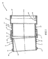
- FIG. 1 illustrates two adjacent tubular elements 11, 11 ′, of the sheath of protection 10.
- Each tubular element 11 has a first section 12 and a second substantially cylindrical and coaxial section 13.
- the outside diameter of the second section 13 is less than the inside diameter of the first section 12.
- This first section is provided with an annular groove 14 formed in its inner wall.
- the second section 13 includes a peripheral annular bead 15 disposed outside and substantially at the end of the second section.
- the width of the annular groove 14 is substantially greater than the width of the annular peripheral bead 15.
- the bottom of the annular groove 14 forms a first bearing surface 16 of which the section through an axial plane defines a first arc of a circle.
- the bead annular device 15 has a second bearing surface 17 disposed at its periphery, the section of which by an axial plane defines a second arc.
- the annular peripheral bead 15 'of the tubular element 11' is engaged of force in the annular groove 14 of the adjacent tubular element 11 for allow the tubular elements to be hooked together.
- the annular peripheral bead 15 ′ has a face external 18 'bevelled or rounded, directed towards the outside of the element tubular 11 '.
- the first section 12 has at its free end a face internal 19 bevelled or rounded, directed towards the outside of the tubular element 11.
- the protective sheath 10 is formed from a synthetic material thermoformable for example. The force fit of the elements tubular 11, 11 'is made hot for example.
- Each tubular element 11 has two reinforcing ribs 20 circular, arranged at the periphery of the second section 13 between the annular peripheral bead 15 and the first section 12 for example. These reinforcing ribs 20 make it possible to increase the rigidity of the elements tubular while limiting the thickness of their walls.
- the outside diameter of the second section 13 'of the element 11' being smaller the inside diameter of the first section 12 of the adjacent element 11, the second section 13 'can pivot angularly and move axially relative to the first section 12.
- the width of the annular groove 14 of element 11 being greater than the width of the annular peripheral bead 15 'of the adjacent element 11', this bead 15 'can also move axially and pivot angularly in the annular groove 14.
- the adjacent tubular elements 11, 11 ' are arranged so that the first bearing surface 16, defined by the bottom of the annular groove 14, of the tubular element 11 is in contact with the second bearing surface 17 ′, formed on the annular peripheral bead 15 ', of the tubular element 11' adjacent, regardless of their relative positions.
- the protective sheath 10 of the invention is therefore generally very flexible.
- the connections between the adjacent tubular elements are waterproof, whatever the relative position of these tubular elements.
- the first arc of the first bearing surface 16 of the groove annular 14 has a radius of curvature substantially equal to that of the second arc of a circle of the second bearing surface 17 of the peripheral bead annular 15 for example.
- the first and second arc can be centered on the axis of the tubular element 11. Therefore, we obtain approximately a ball joint between two tubular elements adjacent 11 and 11 '.
- the protective sheath 10 is then extremely flexible, because two adjacent elements can very easily rotate angularly relative to each other. It should be noted that two adjacent elements can always move axially relative to each other by exerting a slight effort.
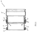
- FIG. 2 illustrates an alternative embodiment of the protective sheath 10 of the invention.
- Reinforcement ribs have been removed on the elements tubular.
- Each tubular element 11 has two annular grooves 21, for example, formed in the annular peripheral bead 15 of the second section 13.
- the depth of the two grooves 21 is substantially equal to the thickness of the bead 15 and the grooves share axially the bead 15 in three parts of approximately equal width for example.
- the tubular element 11 comprises two sealing members 22, such as O-rings, housed in the annular grooves 21.
- the seals 22 'of an element tubular 11 ' are compressed into their respective grooves 21' by the first bearing surface 16 of the annular groove 14 of the tubular element 11 adjacent, thereby increasing the degree of tightness between two elements adjacent tubulars 11, 11 '.
- organs sealing 22, 22 'in the grooves 21, 21' makes it possible to limit the pressure of contact between the first bearing surface 16, defined by the bottom of the groove 14, of a tubular element 11 and the second bearing surface 17 ', formed on the bead 15 ′ of the tubular element 1 adjoining it.
- Contact pressure is related to the radial dimensions of the groove and the bead. This allows obtaining a more flexible protective sheath 10 and better sealing, even under conditions of extreme use, for example if the sheath is immersed in a liquid under high pressure.
- the maximum angular pivoting between two adjacent tubular elements is limited by their shapes and dimensions, in particular by the width of the annular groove and the peripheral bead annular.
- the maximum pivot angle is between 1 and 15 degrees, for example, and is preferably equal to 3 degrees. In the latter case, it is necessary to fit thirty tubular elements so that the sheath protection 10 could form a 90 degree bend for example.
- the protective sheath 10 can be used in particular to connect two straight and rigid protective sleeves.
- the two tubular elements end of the protective sheath 10 are then arranged to be connected to these two rigid rectilinear protective sheaths.
- the tubular elements must have a certain rigidity to guarantee good protection against crushing and against impact.
- the thickness of walls of the tubular elements is determined by the material used, by the loads undergone during their use and by the desired safety factor. These criteria can be decisive when the sheath is buried or when it protects relatively fragile cables and / or conduits, for example.
- the tubular elements can be formed from a synthetic material or in another suitable matter. Obviously, matter can also be chosen so that the sheath has particular properties, such as resistance to heat, radiation or corrosive medium by example.
- the protective sheath of the invention is simple to manufacture. She is very resistant to impact and crushing. It is generally flexible or flexible, which is an undeniable advantage when it must be implanted in hard to reach places, such as bloodletting, excavations or similar.
- the protective sheath is modular. It can be presented under different shapes, namely in different diameters, in different lengths, by changing the number of tubular elements. She therefore adapts very good for all installation configurations.
- the angular opening between its two ends can vary from 0 to 90 degrees, or even more if necessary, with a radius of curvature chosen for a determined angular opening. Finally, it is perfectly waterproof. Consequently, it does not require no additional means or operation, such as installing a mandatory heat shrinkable envelope with sheaths protection of the prior art. Therefore, it is ultimately inexpensive.
- the tubular elements of the sheath protection may have different lengths.
- the annular bead can be placed inside the first large diameter section and the annular groove formed outside the second small diameter section of each tubular element.
Landscapes
- Engineering & Computer Science (AREA)
- General Engineering & Computer Science (AREA)
- Mechanical Engineering (AREA)
- Architecture (AREA)
- Civil Engineering (AREA)
- Structural Engineering (AREA)
- Joints Allowing Movement (AREA)
- Laying Of Electric Cables Or Lines Outside (AREA)
- Details Of Indoor Wiring (AREA)
- Quick-Acting Or Multi-Walled Pipe Joints (AREA)
- Protection Of Pipes Against Damage, Friction, And Corrosion (AREA)
Abstract
Description
- la figure 1 est une vue en coupe axiale représentant une partie de la gaine de protection selon un mode de réalisation de l'invention; et
- la figure 2 est une vue en coupe axiale représentant une variante de réalisation de la gaine de protection de la figure 1.
Claims (8)
- Gaine de protection pour câbles ou conduits, notamment des câbles de transport d'énergie, des câbles de télécommunications ou des conduits de fluides, cette gaine de protection étant constituée de plusieurs éléments tubulaires indépendants emboítés, respectivement agencés pour pivoter angulairement et se déplacer axialement les uns par rapport aux autres, chaque élément tubulaire comportant d'une part une gorge annulaire et d'autre part un bourrelet périphérique annulaire, la largeur de ladite gorge annulaire étant supérieure à la largeur dudit bourrelet périphérique annulaire, ledit bourrelet périphérique annulaire d'un élément tubulaire étant engagé de force dans la gorge annulaire d'un élément tubulaire adjacent et étant agencé pour se déplacer axialement et angulairement dans cette gorge annulaire, caractérisée en ce que ladite gorge annulaire (14, 14') comporte une première surface d'appui (16, 16') qui constitue le fond de cette gorge annulaire et dont la section par un plan axial définit un premier arc de cercle, en ce que le bourrelet périphérique annulaire (15, 15') comporte une deuxième surface d'appui (17, 17') disposée à sa périphérie, et en ce que la première surface d'appui (16) d'un élément tubulaire (11) est en contact avec la deuxième surface d'appui (17') d'un élément tubulaire adjacent (11') et définit une liaison étanche quelles que soient les positions relatives desdits éléments tubulaires adjacents (11, 11').
- Gaine de protection selon la revendication 1, caractérisée en ce que ladite deuxième surface d'appui (17, 17') a une section par un plan axial qui définit un deuxième arc de cercle.
- Gaine de protection selon la revendication 2, caractérisée en ce que ledit deuxième arc de cercle de ladite deuxième surface d'appui (17, 17') et ledit premier arc de cercle de ladite première surface d'appui (16, 16') ont des rayons de courbure sensiblement égaux.
- Gaine de protection selon la revendication 3, caractérisée en ce que ledit premier arc de cercle et ledit deuxième arc de cercle sont centrés sur l'axe de l'élément tubulaire (11, 11').
- Gaine de protection selon la revendication 1, caractérisée en ce que chaque élément tubulaire (11, 11') comporte au moins une rainure annulaire (21, 21') ménagée dans ledit bourrelet périphérique annulaire (15, 15').
- Gaine de protection selon la revendication 5, caractérisée en ce que chaque élément tubulaire (11, 11') comporte un organe d'étanchéité (22, 22') logé dans ladite rainure annulaire (21, 21').
- Gaine de protection selon la revendication 1, caractérisée en ce que chaque élément tubulaire (11, 11') comporte un premier tronçon (12, 12') et un deuxième tronçon (13, 13') sensiblement cylindriques et coaxiaux, le diamètre extérieur du deuxième tronçon (13, 13') étant inférieur au diamètre intérieur du premier tronçon (12, 12'), et en ce que ladite gorge annulaire (14, 14') est ménagée à l'intérieur du premier tronçon (12, 12') et ledit bourrelet périphérique annulaire (15, 15') est disposé à l'extérieur du deuxième tronçon (13, 13').
- Gaine de protection selon la revendication 1, caractérisée en ce que la largeur de ladite gorge annulaire (14, 14') et la largeur dudit bourrelet périphérique annulaire (15, 15') sont définies de sorte que l'angle de pivotement angulaire entre deux éléments tubulaires adjacents (11, 11') soit compris entre 1 et 15 degrés et de préférence approximativement égal à 3 degrés.
Applications Claiming Priority (2)
| Application Number | Priority Date | Filing Date | Title |
|---|---|---|---|
| FR9807667 | 1998-06-15 | ||
| FR9807667A FR2779800B1 (fr) | 1998-06-15 | 1998-06-15 | Gaine de protection pour cables ou conduits |
Publications (2)
| Publication Number | Publication Date |
|---|---|
| EP0965784A1 true EP0965784A1 (fr) | 1999-12-22 |
| EP0965784B1 EP0965784B1 (fr) | 2003-09-10 |
Family
ID=9527523
Family Applications (1)
| Application Number | Title | Priority Date | Filing Date |
|---|---|---|---|
| EP99810451A Expired - Lifetime EP0965784B1 (fr) | 1998-06-15 | 1999-05-25 | Gaine de protection pour câbles ou conduits |
Country Status (5)
| Country | Link |
|---|---|
| EP (1) | EP0965784B1 (fr) |
| AT (1) | ATE249600T1 (fr) |
| DE (1) | DE69911119T2 (fr) |
| ES (1) | ES2207158T3 (fr) |
| FR (1) | FR2779800B1 (fr) |
Cited By (9)
| Publication number | Priority date | Publication date | Assignee | Title |
|---|---|---|---|---|
| EP1388700A1 (fr) * | 2002-08-06 | 2004-02-11 | Reiku GmbH | Gaine formée par une succession des membres articulés |
| FR2929642A1 (fr) * | 2008-04-07 | 2009-10-09 | Contitech Anoflex Sas Soc Par | Tube d'alimentation en lubrifiant d'un turbocompresseur. |
| CN103227433A (zh) * | 2013-04-25 | 2013-07-31 | 江苏易鼎电力科技有限公司 | 倍容导线接续管用镶嵌式万向保护套 |
| CN104565595A (zh) * | 2015-01-27 | 2015-04-29 | 潍坊倍力汽车零部件有限公司 | 挠性管 |
| EP2381551A3 (fr) * | 2010-04-20 | 2015-06-03 | Roland Elkuch | Tuyau de protection de câbles flexible |
| EP3024101A1 (fr) * | 2014-11-18 | 2016-05-25 | Dipl.-Ing. Dr. Ernst Vogelsang GmbH & Co. KG | Tube de protection souple |
| GB2547184A (en) * | 2015-12-22 | 2017-08-16 | Northstone (Ni) Ltd | A ducting assembly |
| EP3499665A1 (fr) * | 2017-12-15 | 2019-06-19 | Radiall | Rallonge articulee de raccord sur câble pour connecteur destine a etre relie a au moins un câble |
| CN114373572A (zh) * | 2022-02-22 | 2022-04-19 | 中海油田服务股份有限公司 | 一种用于炮缆防折装置 |
Families Citing this family (3)
| Publication number | Priority date | Publication date | Assignee | Title |
|---|---|---|---|---|
| DE102015121845A1 (de) * | 2015-12-15 | 2017-06-22 | Witzenmann Gmbh | Modularer Metallschlauch sowie Vorrichtung und Verfahren zu dessen Herstellung |
| FR3072220B1 (fr) | 2017-10-05 | 2020-10-30 | Latelec | Harnais de liason electrique monolitique a rigidite adaptee |
| US11848546B2 (en) * | 2021-02-01 | 2023-12-19 | Magna Powertrain Of America, Inc. | High voltage wire protection system for electric vehicles |
Citations (3)
| Publication number | Priority date | Publication date | Assignee | Title |
|---|---|---|---|---|
| DE3909839A1 (de) | 1989-03-25 | 1989-10-19 | Daimler Benz Ag | Marderschutzeinrichtung |
| US5353843A (en) * | 1992-12-10 | 1994-10-11 | Crown Industries, Inc. | Method and apparatus for protecting a hose |
| DE19601913C1 (de) * | 1996-01-19 | 1997-07-24 | Klaus Fiedler | Rohr- oder Kabelschutz und Verfahren zu dessen Herstellung |
-
1998
- 1998-06-15 FR FR9807667A patent/FR2779800B1/fr not_active Expired - Fee Related
-
1999
- 1999-05-25 AT AT99810451T patent/ATE249600T1/de active
- 1999-05-25 DE DE69911119T patent/DE69911119T2/de not_active Expired - Lifetime
- 1999-05-25 ES ES99810451T patent/ES2207158T3/es not_active Expired - Lifetime
- 1999-05-25 EP EP99810451A patent/EP0965784B1/fr not_active Expired - Lifetime
Patent Citations (3)
| Publication number | Priority date | Publication date | Assignee | Title |
|---|---|---|---|---|
| DE3909839A1 (de) | 1989-03-25 | 1989-10-19 | Daimler Benz Ag | Marderschutzeinrichtung |
| US5353843A (en) * | 1992-12-10 | 1994-10-11 | Crown Industries, Inc. | Method and apparatus for protecting a hose |
| DE19601913C1 (de) * | 1996-01-19 | 1997-07-24 | Klaus Fiedler | Rohr- oder Kabelschutz und Verfahren zu dessen Herstellung |
Cited By (11)
| Publication number | Priority date | Publication date | Assignee | Title |
|---|---|---|---|---|
| EP1388700A1 (fr) * | 2002-08-06 | 2004-02-11 | Reiku GmbH | Gaine formée par une succession des membres articulés |
| FR2929642A1 (fr) * | 2008-04-07 | 2009-10-09 | Contitech Anoflex Sas Soc Par | Tube d'alimentation en lubrifiant d'un turbocompresseur. |
| EP2381551A3 (fr) * | 2010-04-20 | 2015-06-03 | Roland Elkuch | Tuyau de protection de câbles flexible |
| CN103227433A (zh) * | 2013-04-25 | 2013-07-31 | 江苏易鼎电力科技有限公司 | 倍容导线接续管用镶嵌式万向保护套 |
| EP3024101A1 (fr) * | 2014-11-18 | 2016-05-25 | Dipl.-Ing. Dr. Ernst Vogelsang GmbH & Co. KG | Tube de protection souple |
| CN104565595A (zh) * | 2015-01-27 | 2015-04-29 | 潍坊倍力汽车零部件有限公司 | 挠性管 |
| CN104565595B (zh) * | 2015-01-27 | 2016-10-05 | 潍坊倍力汽车零部件有限公司 | 挠性管 |
| GB2547184A (en) * | 2015-12-22 | 2017-08-16 | Northstone (Ni) Ltd | A ducting assembly |
| EP3499665A1 (fr) * | 2017-12-15 | 2019-06-19 | Radiall | Rallonge articulee de raccord sur câble pour connecteur destine a etre relie a au moins un câble |
| FR3075493A1 (fr) * | 2017-12-15 | 2019-06-21 | Radiall | Rallonge articulee de raccord sur cable pour connecteur destine a etre relie a au moins un cable |
| CN114373572A (zh) * | 2022-02-22 | 2022-04-19 | 中海油田服务股份有限公司 | 一种用于炮缆防折装置 |
Also Published As
| Publication number | Publication date |
|---|---|
| ATE249600T1 (de) | 2003-09-15 |
| EP0965784B1 (fr) | 2003-09-10 |
| ES2207158T3 (es) | 2004-05-16 |
| DE69911119D1 (de) | 2003-10-16 |
| FR2779800B1 (fr) | 2000-09-01 |
| DE69911119T2 (de) | 2004-06-17 |
| FR2779800A1 (fr) | 1999-12-17 |
Similar Documents
| Publication | Publication Date | Title |
|---|---|---|
| EP0870967B1 (fr) | Joint verrouillé entre éléments de canalisation et jonc fendu métallique utilisable dans un tel joint | |
| EP0965784B1 (fr) | Gaine de protection pour câbles ou conduits | |
| EP1273843B1 (fr) | Raccord récupérable adaptable aux extrémités d'un tuyau souple armé | |
| EP1328749B1 (fr) | Raccord hydraulique flexible | |
| FR2704042A1 (fr) | Joint FS pour tuyau de grand diamètre. | |
| FR2708328A1 (fr) | Raccord de tuyau et son procédé d'assemblage. | |
| FR2683017A1 (fr) | Raccord pour tubes. | |
| FR2740199A1 (fr) | Manchon modulaire pour la protection, la reparation ou la renovation d'une canalisation | |
| BE1008705A3 (fr) | Raccord de fixation pour un tube annele. | |
| FR2783590A1 (fr) | Dispositif de raccordement instantane pour tuyau | |
| CA2342733A1 (fr) | Dispositif de connexion pour conduits | |
| EP1413815B1 (fr) | Dispositif de raccordement de deux tubes possédant une extrémité évasée | |
| EP0470918B1 (fr) | Joint entre éléments de tuyauterie | |
| FR2759762A1 (fr) | Raccord isolant dielectrique et procede d'assemblage d'un tel raccord | |
| EP0611875B1 (fr) | Ligne de tuyaux de fonçage et tuyau de fonçage correspondant | |
| FR2581437A1 (fr) | Joint d'etancheite aux fluides exterieurs a une canalisation pour la jonction de deux tuyaux a bout male et emboitement calorifuges | |
| EP1197707B1 (fr) | Ensemble de deux conduits de gaz chauds raccordés au moyen d'un coupleur et procédé de raccordement | |
| CH639508A5 (en) | Protective jacket for telecommunication and/or power-transmission cables | |
| EP1450094B1 (fr) | Dispositif d'assemblage de tuyaux cylindriques | |
| EP1133654B1 (fr) | Dispositif de raccordement d'une conduite metallique | |
| EP0490725B1 (fr) | Dispositif d'obturation d'un passage tubulaire de cable | |
| EP0441686A1 (fr) | Dispositif de raccordement étanche de deux éléments identiques de canalisation | |
| EP0538113B1 (fr) | Rouleaux conducteurs de courant notamment pour lignes d'électrolyse | |
| FR2734337A1 (fr) | Ensemble de flexible pour gaz, muni de raccords | |
| FR3140145A1 (fr) | Embout mâle pour raccord fluidique pour circuit de transfert de fluide. |
Legal Events
| Date | Code | Title | Description |
|---|---|---|---|
| PUAI | Public reference made under article 153(3) epc to a published international application that has entered the european phase |
Free format text: ORIGINAL CODE: 0009012 |
|
| AK | Designated contracting states |
Kind code of ref document: A1 Designated state(s): AT BE CH CY DE DK ES FI FR GB GR IE IT LI LU MC NL PT SE |
|
| AX | Request for extension of the european patent |
Free format text: AL;LT;LV;MK;RO;SI |
|
| 17P | Request for examination filed |
Effective date: 20000517 |
|
| AKX | Designation fees paid |
Free format text: AT BE CH CY DE DK ES FI FR GB GR IE IT LI LU MC NL PT SE |
|
| RAP1 | Party data changed (applicant data changed or rights of an application transferred) |
Owner name: PLASTOMER AG |
|
| GRAH | Despatch of communication of intention to grant a patent |
Free format text: ORIGINAL CODE: EPIDOS IGRA |
|
| GRAH | Despatch of communication of intention to grant a patent |
Free format text: ORIGINAL CODE: EPIDOS IGRA |
|
| GRAA | (expected) grant |
Free format text: ORIGINAL CODE: 0009210 |
|
| AK | Designated contracting states |
Kind code of ref document: B1 Designated state(s): AT BE CH CY DE DK ES FI FR GB GR IE IT LI LU MC NL PT SE |
|
| PG25 | Lapsed in a contracting state [announced via postgrant information from national office to epo] |
Ref country code: IE Free format text: LAPSE BECAUSE OF FAILURE TO SUBMIT A TRANSLATION OF THE DESCRIPTION OR TO PAY THE FEE WITHIN THE PRESCRIBED TIME-LIMIT Effective date: 20030910 Ref country code: FI Free format text: LAPSE BECAUSE OF FAILURE TO SUBMIT A TRANSLATION OF THE DESCRIPTION OR TO PAY THE FEE WITHIN THE PRESCRIBED TIME-LIMIT Effective date: 20030910 Ref country code: CY Free format text: LAPSE BECAUSE OF FAILURE TO SUBMIT A TRANSLATION OF THE DESCRIPTION OR TO PAY THE FEE WITHIN THE PRESCRIBED TIME-LIMIT Effective date: 20030910 |
|
| REG | Reference to a national code |
Ref country code: GB Ref legal event code: FG4D Free format text: NOT ENGLISH |
|
| REG | Reference to a national code |
Ref country code: CH Ref legal event code: EP |
|
| REF | Corresponds to: |
Ref document number: 69911119 Country of ref document: DE Date of ref document: 20031016 Kind code of ref document: P |
|
| REG | Reference to a national code |
Ref country code: IE Ref legal event code: FG4D Free format text: FRENCH |
|
| PG25 | Lapsed in a contracting state [announced via postgrant information from national office to epo] |
Ref country code: SE Free format text: LAPSE BECAUSE OF FAILURE TO SUBMIT A TRANSLATION OF THE DESCRIPTION OR TO PAY THE FEE WITHIN THE PRESCRIBED TIME-LIMIT Effective date: 20031210 Ref country code: GR Free format text: LAPSE BECAUSE OF FAILURE TO SUBMIT A TRANSLATION OF THE DESCRIPTION OR TO PAY THE FEE WITHIN THE PRESCRIBED TIME-LIMIT Effective date: 20031210 Ref country code: DK Free format text: LAPSE BECAUSE OF FAILURE TO SUBMIT A TRANSLATION OF THE DESCRIPTION OR TO PAY THE FEE WITHIN THE PRESCRIBED TIME-LIMIT Effective date: 20031210 |
|
| REG | Reference to a national code |
Ref country code: CH Ref legal event code: NV Representative=s name: CRONIN INTELLECTUAL PROPERTY |
|
| PG25 | Lapsed in a contracting state [announced via postgrant information from national office to epo] |
Ref country code: PT Free format text: LAPSE BECAUSE OF FAILURE TO SUBMIT A TRANSLATION OF THE DESCRIPTION OR TO PAY THE FEE WITHIN THE PRESCRIBED TIME-LIMIT Effective date: 20031218 |
|
| GBT | Gb: translation of ep patent filed (gb section 77(6)(a)/1977) |
Effective date: 20040106 |
|
| REG | Reference to a national code |
Ref country code: IE Ref legal event code: FD4D |
|
| REG | Reference to a national code |
Ref country code: ES Ref legal event code: FG2A Ref document number: 2207158 Country of ref document: ES Kind code of ref document: T3 |
|
| PLBE | No opposition filed within time limit |
Free format text: ORIGINAL CODE: 0009261 |
|
| STAA | Information on the status of an ep patent application or granted ep patent |
Free format text: STATUS: NO OPPOSITION FILED WITHIN TIME LIMIT |
|
| 26N | No opposition filed |
Effective date: 20040614 |
|
| PGFP | Annual fee paid to national office [announced via postgrant information from national office to epo] |
Ref country code: NL Payment date: 20120530 Year of fee payment: 14 Ref country code: MC Payment date: 20120529 Year of fee payment: 14 Ref country code: LU Payment date: 20120531 Year of fee payment: 14 |
|
| PGFP | Annual fee paid to national office [announced via postgrant information from national office to epo] |
Ref country code: FR Payment date: 20120626 Year of fee payment: 14 |
|
| PGFP | Annual fee paid to national office [announced via postgrant information from national office to epo] |
Ref country code: IT Payment date: 20120530 Year of fee payment: 14 |
|
| PGFP | Annual fee paid to national office [announced via postgrant information from national office to epo] |
Ref country code: BE Payment date: 20120619 Year of fee payment: 14 Ref country code: GB Payment date: 20120726 Year of fee payment: 14 |
|
| PGFP | Annual fee paid to national office [announced via postgrant information from national office to epo] |
Ref country code: ES Payment date: 20120629 Year of fee payment: 14 |
|
| PGFP | Annual fee paid to national office [announced via postgrant information from national office to epo] |
Ref country code: AT Payment date: 20120531 Year of fee payment: 14 |
|
| BERE | Be: lapsed |
Owner name: *PLASTOMER A.G. Effective date: 20130531 |
|
| REG | Reference to a national code |
Ref country code: NL Ref legal event code: V1 Effective date: 20131201 |
|
| PG25 | Lapsed in a contracting state [announced via postgrant information from national office to epo] |
Ref country code: MC Free format text: LAPSE BECAUSE OF NON-PAYMENT OF DUE FEES Effective date: 20130531 |
|
| REG | Reference to a national code |
Ref country code: AT Ref legal event code: MM01 Ref document number: 249600 Country of ref document: AT Kind code of ref document: T Effective date: 20130531 |
|
| GBPC | Gb: european patent ceased through non-payment of renewal fee |
Effective date: 20130525 |
|
| PG25 | Lapsed in a contracting state [announced via postgrant information from national office to epo] |
Ref country code: AT Free format text: LAPSE BECAUSE OF NON-PAYMENT OF DUE FEES Effective date: 20130531 |
|
| PG25 | Lapsed in a contracting state [announced via postgrant information from national office to epo] |
Ref country code: IT Free format text: LAPSE BECAUSE OF NON-PAYMENT OF DUE FEES Effective date: 20130525 Ref country code: NL Free format text: LAPSE BECAUSE OF NON-PAYMENT OF DUE FEES Effective date: 20131201 Ref country code: BE Free format text: LAPSE BECAUSE OF NON-PAYMENT OF DUE FEES Effective date: 20130531 |
|
| REG | Reference to a national code |
Ref country code: FR Ref legal event code: ST Effective date: 20140131 |
|
| PG25 | Lapsed in a contracting state [announced via postgrant information from national office to epo] |
Ref country code: GB Free format text: LAPSE BECAUSE OF NON-PAYMENT OF DUE FEES Effective date: 20130525 |
|
| PG25 | Lapsed in a contracting state [announced via postgrant information from national office to epo] |
Ref country code: FR Free format text: LAPSE BECAUSE OF NON-PAYMENT OF DUE FEES Effective date: 20130531 |
|
| REG | Reference to a national code |
Ref country code: ES Ref legal event code: FD2A Effective date: 20150710 |
|
| PG25 | Lapsed in a contracting state [announced via postgrant information from national office to epo] |
Ref country code: ES Free format text: LAPSE BECAUSE OF NON-PAYMENT OF DUE FEES Effective date: 20130526 Ref country code: LU Free format text: LAPSE BECAUSE OF NON-PAYMENT OF DUE FEES Effective date: 20130525 |
|
| PGFP | Annual fee paid to national office [announced via postgrant information from national office to epo] |
Ref country code: DE Payment date: 20150528 Year of fee payment: 17 |
|
| REG | Reference to a national code |
Ref country code: DE Ref legal event code: R119 Ref document number: 69911119 Country of ref document: DE |
|
| PG25 | Lapsed in a contracting state [announced via postgrant information from national office to epo] |
Ref country code: DE Free format text: LAPSE BECAUSE OF NON-PAYMENT OF DUE FEES Effective date: 20161201 |
|
| REG | Reference to a national code |
Ref country code: CH Ref legal event code: NV Representative=s name: NOTARIAT WEBER, CH |
|
| PGFP | Annual fee paid to national office [announced via postgrant information from national office to epo] |
Ref country code: CH Payment date: 20180618 Year of fee payment: 20 |
|
| REG | Reference to a national code |
Ref country code: CH Ref legal event code: PL |