EP0965748A1 - Kraftstoffmess- und Druckbeaufschlagungssystem für Fahrzeugkraftstoffbehälter und Behälter damit ausgerüstet - Google Patents
Kraftstoffmess- und Druckbeaufschlagungssystem für Fahrzeugkraftstoffbehälter und Behälter damit ausgerüstet Download PDFInfo
- Publication number
- EP0965748A1 EP0965748A1 EP99401451A EP99401451A EP0965748A1 EP 0965748 A1 EP0965748 A1 EP 0965748A1 EP 99401451 A EP99401451 A EP 99401451A EP 99401451 A EP99401451 A EP 99401451A EP 0965748 A1 EP0965748 A1 EP 0965748A1
- Authority
- EP
- European Patent Office
- Prior art keywords
- assembly
- gauging
- base
- guide
- tank
- Prior art date
- Legal status (The legal status is an assumption and is not a legal conclusion. Google has not performed a legal analysis and makes no representation as to the accuracy of the status listed.)
- Granted
Links
Images


Classifications
-
- F—MECHANICAL ENGINEERING; LIGHTING; HEATING; WEAPONS; BLASTING
- F02—COMBUSTION ENGINES; HOT-GAS OR COMBUSTION-PRODUCT ENGINE PLANTS
- F02M—SUPPLYING COMBUSTION ENGINES IN GENERAL WITH COMBUSTIBLE MIXTURES OR CONSTITUENTS THEREOF
- F02M37/00—Apparatus or systems for feeding liquid fuel from storage containers to carburettors or fuel-injection apparatus; Arrangements for purifying liquid fuel specially adapted for, or arranged on, internal-combustion engines
- F02M37/04—Feeding by means of driven pumps
- F02M37/08—Feeding by means of driven pumps electrically driven
- F02M37/10—Feeding by means of driven pumps electrically driven submerged in fuel, e.g. in reservoir
- F02M37/103—Mounting pumps on fuel tanks
Definitions
- the present invention relates to the field of sets of gauging and drawing fuel from a vehicle tank automobile.
- the present invention relates to means support of a fuel gauging and drawing assembly with respect to to a base intended to be fixed to a wall of the tank.
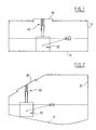
- FIGS. 1 and 2 the means for translational guidance and for stress on the gauging and drawing assembly 20, are referenced 40.
- the Applicant has found that this provision does not not always satisfactory, especially when the support base 30 is not fixed on a horizontal upper wall of the tank, but on an inclined wall. Indeed in this case the set of gauging and drawing 20 may not be properly pressed against the bottom 12 of the tank, as seen for example in Figure 2. Also in this case the point of contact on the bottom 12 of the tank depends both on the relative inclination, itself fluctuating, between the support wall of the base 30 and the bottom 12 of the tank, and the indexing of the base 30 on its support wall, that is to say of the angular position of this base 30 relative to its support wall around the axis of translation of the assembly of gauging and drawing.
- the present invention now aims to propose again means with higher performance than the devices known prior.
- the object of the present invention is in particular to provide means allowing reliable gauging and drawing whatever the inclination of the tank support wall which carries the base of this gauging and drawing assembly, and whatever the deformations from the bottom of the tank.
- a fuel gauging and drawing system comprising a support base intended to be fixed on a tank wall and a gauging and drawing assembly mounted to displacement on the base support and biased towards the bottom of the tank, relative to this base, characterized in that the connecting means between the support base and the set of gauging and drawing includes at least two guide assemblies allowing one a translation and a relative swiveling and the other a translation and a displacement in a plane passing through the axis of associated translation.
- the above-mentioned deflection plan also passes through the axis of translation of the first guide assembly.
- the present invention also relates to the tanks thus equipped.
- the gauging assembly and drawing 120 comprises a pump and a level detection means fuel in the tank, for example float operated, while that the support base 130 comprises a plate 132 adapted to be fixed tightly on a wall of the tank and which is crossed on the one hand by pipes connected to the pump and on the other hand by connections connected to the level detection means.
- the support base 130 is provided with two chambers 140, 150 which open on its lower surface, in direction of the whole 120.
- One 150 of the two chambers has a circular cross section of revolution and constant over its entire length.
- the other chamber 140 has an oblong section and constant over its entire length.
- this chamber 140 is delimited by two circular sectors 141, 142 interconnected by two flats 143, 144 parallel to each other.
- these two flats 143, 144 are parallel to the plane defined by the axes 145, 155 of the two chambers 140, 150.
- the drawing assembly 120 is in turn provided at its top with two drums 122 and 124 adapted to be engaged respectively in the rooms 140 and 150.
- each of the drums 122, 124 is provided with a protrusion 123, 125 in the form of a spherical cap, near its upper end.
- the cross section of the drums 122, 124 is less than that of the rooms 140, 150.
- the outgrowth 125 has a diameter complementary to the diameter of chamber 150.
- the projection 125 and the barrel 124 associated are susceptible of translation inside the chamber 150 along the axis of this, in a generally vertical direction and / or of a swiveling by relation to this around the center of the outgrowth 125.
- the outgrowth 123 has a diameter complementary to the distance separating the two flats 143 and 144.
- the protrusion 123 and the barrel 122 associates are susceptible of translation inside the chamber 140 and / or a deflection relative thereto transversely to the axis 145 and parallel to the flats 143, 144. Therefore the defined cooperation between the ball joint 123 and the chamber 140 ensures indexing of the assembly 120 relative to the base 130.
- This guide structure allows a precise guidance of the assembly 120 allowing permanent support of this the latter by its lower surface, on the bottom of the tank, whatever the deformations of this bottom (rotation and / or translation) and / or its inclination relative to the wall of the tank which carries the base 130, as we have shown schematically in Figure 6.
- drums 122, 124 are hollow and receive descending columns 146, 156 secured to the bottom of the rooms 140, 150 and centered on them.
- These columns 146, 156 serve as central support for spiral springs 147, 157 interposed between the base 130 and the assembly 120, to request this last towards the bottom of the tank.
- the springs 147, 157 are supported respectively on the bottom of chambers 140, 150 and on recesses 148, 158 formed inside the barrels 122, 124.
- FIG. 5 illustrates an alternative embodiment according to which the columns 146, 156 integral with the base 130 and serving to guide the springs 147, 157 are replaced by risers 1460, 1560 integral with the top of the barrels 122, 124, and emerging beyond the spherical protuberances 123, 125, to ensure the same function of spring guide 147, 157.
- the above-mentioned columns 146, 156 and 1460, 1560 are tapered, tapered away from their support, so as not to disturb the aforementioned relative displacement between the base 130 and the assembly 120.
- the device according to the present invention offers in particular the following advantages.
- the device according to the present invention makes it possible to maintain an indexing of the assembly 120 relative to the support base 130.
- the present invention makes it possible to precisely control the path of the gauging float and avoid any collision of this float with the tank walls. This is especially important with tanks exploited nowadays because these tanks often have forms complexes adapted to best occupy the space available in vehicle infrastructure.
- the present invention also makes it possible to facilitate the mounting of gauging and drawing devices, since it allows mounting separately and successively the gauging and drawing assembly 120 and the base 130.
- the ball joint 123 and the chamber 140 associated could be replaced by a straight central guide 1400 integral with one of the assembly 120 or the base 130 and defining the direction of travel allowed and two lateral bearing surfaces 1230, for example in the form of spherical caps integral with each other the base 130 or of the assembly 120 and resting on said guide 1400, as shown schematically in Figure 7.
- the management of authorized travel may not be parallel to the plane defined by the axes rooms 140, 150, but inclined relative to this plane.
- At least one of the guide assemblies can define a hydraulic connection between the gauging assembly 120 and the support base 130.
- This hydraulic connection is preferably defined by the assembly of guide which ensures translation and relative swiveling.
- a hollow tube 156 secured to the support base 130 and which plunges into a tank 124 integral with the gauging assembly 120.
- the internal volume of tubing 156 communicates with the internal volume of the fut 124.
- the geometry of the upper end of fut 124 is suitable for ensure translation and relative swiveling relative to the pipe 156.
- It sealing means are also provided, such as an O-ring 170, preferably with radial compression, between tubing 156 and was 124. This seal 170 is preferably provided as close as possible to the swiveling center.
- Such a hydraulic connection can be used for example for deliver fuel from a pump located in a tank to injectors or to a carburetor.
Landscapes
- Engineering & Computer Science (AREA)
- Chemical & Material Sciences (AREA)
- Combustion & Propulsion (AREA)
- Mechanical Engineering (AREA)
- General Engineering & Computer Science (AREA)
- Cooling, Air Intake And Gas Exhaust, And Fuel Tank Arrangements In Propulsion Units (AREA)
Applications Claiming Priority (2)
| Application Number | Priority Date | Filing Date | Title |
|---|---|---|---|
| FR9807575 | 1998-06-16 | ||
| FR9807575A FR2779773B1 (fr) | 1998-06-16 | 1998-06-16 | Systeme de jaugeage et de puisage de carburant pour reservoir de vehicule automobile et reservoir ainsi equipe |
Publications (2)
| Publication Number | Publication Date |
|---|---|
| EP0965748A1 true EP0965748A1 (de) | 1999-12-22 |
| EP0965748B1 EP0965748B1 (de) | 2003-01-29 |
Family
ID=9527447
Family Applications (1)
| Application Number | Title | Priority Date | Filing Date |
|---|---|---|---|
| EP19990401451 Expired - Lifetime EP0965748B1 (de) | 1998-06-16 | 1999-06-14 | Kraftstoffmess- und Entnahmesystem für Fahrzeugkraftstoffbehälter und damit ausgerüsteter Behälter |
Country Status (3)
| Country | Link |
|---|---|
| EP (1) | EP0965748B1 (de) |
| DE (1) | DE69905097T2 (de) |
| FR (1) | FR2779773B1 (de) |
Cited By (2)
| Publication number | Priority date | Publication date | Assignee | Title |
|---|---|---|---|---|
| WO2009040181A1 (de) * | 2007-09-21 | 2009-04-02 | Robert Bosch Gmbh | Kraftstofffördermodul |
| DE10228760B4 (de) | 2001-06-29 | 2019-05-16 | Denso Corporation | Kraftstoffzufuhrvorrichtung |
Citations (5)
| Publication number | Priority date | Publication date | Assignee | Title |
|---|---|---|---|---|
| DE2750081A1 (de) * | 1977-11-09 | 1979-05-10 | Rau Swf Autozubehoer | Brennstoffoerderaggregat |
| EP0297256A2 (de) * | 1987-07-03 | 1989-01-04 | Pierburg Gmbh | Brennstoffördereinheit |
| EP0459556A1 (de) * | 1990-06-01 | 1991-12-04 | General Motors Corporation | Modulare Kraftstoffördereinrichtung |
| EP0705971A1 (de) * | 1994-10-04 | 1996-04-10 | Robert Bosch Gmbh | Vorrichtung zum Fördern von Kraftstoff aus einem Vorratstank zur Brennkraftmaschine eines Kraftfahrzeugs |
| US5522425A (en) * | 1993-10-28 | 1996-06-04 | Bayerische Motoren Werke Ag | Delivery unit with fuel tank level transmitter |
-
1998
- 1998-06-16 FR FR9807575A patent/FR2779773B1/fr not_active Expired - Fee Related
-
1999
- 1999-06-14 EP EP19990401451 patent/EP0965748B1/de not_active Expired - Lifetime
- 1999-06-14 DE DE1999605097 patent/DE69905097T2/de not_active Expired - Fee Related
Patent Citations (5)
| Publication number | Priority date | Publication date | Assignee | Title |
|---|---|---|---|---|
| DE2750081A1 (de) * | 1977-11-09 | 1979-05-10 | Rau Swf Autozubehoer | Brennstoffoerderaggregat |
| EP0297256A2 (de) * | 1987-07-03 | 1989-01-04 | Pierburg Gmbh | Brennstoffördereinheit |
| EP0459556A1 (de) * | 1990-06-01 | 1991-12-04 | General Motors Corporation | Modulare Kraftstoffördereinrichtung |
| US5522425A (en) * | 1993-10-28 | 1996-06-04 | Bayerische Motoren Werke Ag | Delivery unit with fuel tank level transmitter |
| EP0705971A1 (de) * | 1994-10-04 | 1996-04-10 | Robert Bosch Gmbh | Vorrichtung zum Fördern von Kraftstoff aus einem Vorratstank zur Brennkraftmaschine eines Kraftfahrzeugs |
Cited By (3)
| Publication number | Priority date | Publication date | Assignee | Title |
|---|---|---|---|---|
| DE10228760B4 (de) | 2001-06-29 | 2019-05-16 | Denso Corporation | Kraftstoffzufuhrvorrichtung |
| WO2009040181A1 (de) * | 2007-09-21 | 2009-04-02 | Robert Bosch Gmbh | Kraftstofffördermodul |
| US8353422B2 (en) | 2007-09-21 | 2013-01-15 | Robert Bosch Gmbh | Fuel delivery module |
Also Published As
| Publication number | Publication date |
|---|---|
| FR2779773A1 (fr) | 1999-12-17 |
| FR2779773B1 (fr) | 2000-09-01 |
| DE69905097D1 (de) | 2003-03-06 |
| DE69905097T2 (de) | 2003-10-09 |
| EP0965748B1 (de) | 2003-01-29 |
Similar Documents
| Publication | Publication Date | Title |
|---|---|---|
| FR3058743A1 (fr) | Agencement pour la fixation d'un panneau dans une rainure au moyen de deux coins opposes | |
| FR2838681A1 (fr) | Ensemble de puisage de carburant pour vehicules | |
| FR2765632A1 (fr) | Dispositif de puisage de carburant pour reservoir de vehicule automobile | |
| EP2064530A2 (de) | Messgerät mit mehreren sensoren für bordmessfühler | |
| FR2757604A1 (fr) | Dispositif pour raccorder deux elements de conduites en forme de tubes | |
| FR2814200A1 (fr) | Dispositif de puisage et de jaugeage pour reservoir de carburant de vehicule automobile | |
| FR2875858A1 (fr) | Ensemble compose d'un module de puisage et d'un accessoire, inserable dans un reservoir de carburant de vehicule automobile | |
| EP0965748B1 (de) | Kraftstoffmess- und Entnahmesystem für Fahrzeugkraftstoffbehälter und damit ausgerüsteter Behälter | |
| EP0702142B1 (de) | Pumpeneinheit enthaltend einen Druckregler, für Fahrzeugkraftstoffbehälter und Behälter damit ausgerüstet | |
| WO2011104465A2 (fr) | Banc d'essais pour moteur a reaction | |
| FR2779772A1 (fr) | Ensemble de puisage de liquide, notamment pour additif de carburant | |
| FR2894214A1 (fr) | Reservoir de liquide de frein et son systeme de fixation | |
| FR3006393A1 (fr) | Procede d'assemblage de tubes par emmanchement colle et traverse de planche de bord obtenue par un tel procede | |
| EP0681103A1 (de) | Kraftstoffabsaug- und Anzeigevorrichtung eines Fahrzeuges | |
| FR2776025A1 (fr) | Ensemble d'injection de carburant dans un moteur a combustion interne et a injection directe | |
| EP0666415A1 (de) | Interner Druckregler auf einer Druckerhöhungsvorrichtung | |
| EP3814616A1 (de) | Leitvorrichtung in einer brennkammer | |
| FR2739169A1 (fr) | Collier de prise en charge pour le branchement d'un abonne sur une canalisation d'alimentation en eau et procede de percement de la canalisation | |
| FR2737766A1 (fr) | Dispositif pour la fixation rigide et etanche de deux conduits | |
| FR3160396A1 (fr) | Réservoir comprenant au moins un système de liaison à lames de jonction périphériques reliant une structure intérieure et une enceinte, aéronef comportant au moins un tel réservoir | |
| FR2873960A1 (fr) | Dispositif de puisage et/ou jaugeage de carburant | |
| FR2801024A1 (fr) | Ensemble de commande pour vehicules automobiles | |
| FR3073918B1 (fr) | Dispositif anti-retour de fluide monobloc dans un aeronef et procede de fabrication d'un tel dispositif | |
| WO2015104515A1 (fr) | Moteur borgne a combustion interne avec une etancheite aux gaz améliorée | |
| FR3156186A3 (fr) | Réservoir de fluide cryogénique |
Legal Events
| Date | Code | Title | Description |
|---|---|---|---|
| PUAI | Public reference made under article 153(3) epc to a published international application that has entered the european phase |
Free format text: ORIGINAL CODE: 0009012 |
|
| AK | Designated contracting states |
Kind code of ref document: A1 Designated state(s): DE GB IT |
|
| AX | Request for extension of the european patent |
Free format text: AL;LT;LV;MK;RO;SI |
|
| RIN1 | Information on inventor provided before grant (corrected) |
Inventor name: TISSOT, FREDERIC |
|
| 17P | Request for examination filed |
Effective date: 20000306 |
|
| AKX | Designation fees paid |
Free format text: DE GB IT |
|
| GRAG | Despatch of communication of intention to grant |
Free format text: ORIGINAL CODE: EPIDOS AGRA |
|
| RTI1 | Title (correction) |
Free format text: FUEL GAUGING AND DRAWING SYSTEM FOR AUTOMOTIVE VEHICLE FUEL TANK AND TANK EQUIPPED THEREWITH |
|
| 17Q | First examination report despatched |
Effective date: 20020604 |
|
| GRAG | Despatch of communication of intention to grant |
Free format text: ORIGINAL CODE: EPIDOS AGRA |
|
| GRAH | Despatch of communication of intention to grant a patent |
Free format text: ORIGINAL CODE: EPIDOS IGRA |
|
| GRAH | Despatch of communication of intention to grant a patent |
Free format text: ORIGINAL CODE: EPIDOS IGRA |
|
| GRAA | (expected) grant |
Free format text: ORIGINAL CODE: 0009210 |
|
| AK | Designated contracting states |
Designated state(s): DE GB IT |
|
| PG25 | Lapsed in a contracting state [announced via postgrant information from national office to epo] |
Ref country code: IT Free format text: LAPSE BECAUSE OF FAILURE TO SUBMIT A TRANSLATION OF THE DESCRIPTION OR TO PAY THE FEE WITHIN THE PRE;WARNING: LAPSES OF ITALIAN PATENTS WITH EFFECTIVE DATE BEFORE 2007 MAY HAVE OCCURRED AT ANY TIME BEFORE 2007. THE CORRECT EFFECTIVE DATE MAY BE DIFFERENT FROM THE ONE RECORDED.SCRIBED TIME-LIMIT Effective date: 20030129 Ref country code: GB Free format text: LAPSE BECAUSE OF FAILURE TO SUBMIT A TRANSLATION OF THE DESCRIPTION OR TO PAY THE FEE WITHIN THE PRESCRIBED TIME-LIMIT Effective date: 20030129 |
|
| REG | Reference to a national code |
Ref country code: GB Ref legal event code: FG4D Free format text: NOT ENGLISH |
|
| REF | Corresponds to: |
Ref document number: 69905097 Country of ref document: DE Date of ref document: 20030306 Kind code of ref document: P |
|
| GBV | Gb: ep patent (uk) treated as always having been void in accordance with gb section 77(7)/1977 [no translation filed] |
Effective date: 20030129 |
|
| PLBE | No opposition filed within time limit |
Free format text: ORIGINAL CODE: 0009261 |
|
| STAA | Information on the status of an ep patent application or granted ep patent |
Free format text: STATUS: NO OPPOSITION FILED WITHIN TIME LIMIT |
|
| PG25 | Lapsed in a contracting state [announced via postgrant information from national office to epo] |
Ref country code: DE Free format text: LAPSE BECAUSE OF NON-PAYMENT OF DUE FEES Effective date: 20040101 |
|
| 26N | No opposition filed |
Effective date: 20031030 |