EP0965519A2 - Assist power transmission apparatus for power assist vehicle - Google Patents
Assist power transmission apparatus for power assist vehicle Download PDFInfo
- Publication number
- EP0965519A2 EP0965519A2 EP99110314A EP99110314A EP0965519A2 EP 0965519 A2 EP0965519 A2 EP 0965519A2 EP 99110314 A EP99110314 A EP 99110314A EP 99110314 A EP99110314 A EP 99110314A EP 0965519 A2 EP0965519 A2 EP 0965519A2
- Authority
- EP
- European Patent Office
- Prior art keywords
- rotating disk
- shaft
- sensors
- casing
- reduction
- Prior art date
- Legal status (The legal status is an assumption and is not a legal conclusion. Google has not performed a legal analysis and makes no representation as to the accuracy of the status listed.)
- Granted
Links
Images


Classifications
-
- B—PERFORMING OPERATIONS; TRANSPORTING
- B62—LAND VEHICLES FOR TRAVELLING OTHERWISE THAN ON RAILS
- B62M—RIDER PROPULSION OF WHEELED VEHICLES OR SLEDGES; POWERED PROPULSION OF SLEDGES OR SINGLE-TRACK CYCLES; TRANSMISSIONS SPECIALLY ADAPTED FOR SUCH VEHICLES
- B62M6/00—Rider propulsion of wheeled vehicles with additional source of power, e.g. combustion engine or electric motor
- B62M6/40—Rider propelled cycles with auxiliary electric motor
- B62M6/70—Rider propelled cycles with auxiliary electric motor power-driven at single endless flexible member, e.g. chain, between cycle crankshaft and wheel axle, the motor engaging the endless flexible member
-
- B—PERFORMING OPERATIONS; TRANSPORTING
- B62—LAND VEHICLES FOR TRAVELLING OTHERWISE THAN ON RAILS
- B62M—RIDER PROPULSION OF WHEELED VEHICLES OR SLEDGES; POWERED PROPULSION OF SLEDGES OR SINGLE-TRACK CYCLES; TRANSMISSIONS SPECIALLY ADAPTED FOR SUCH VEHICLES
- B62M6/00—Rider propulsion of wheeled vehicles with additional source of power, e.g. combustion engine or electric motor
- B62M6/40—Rider propelled cycles with auxiliary electric motor
Definitions
- the present invention relates to an assist power transmission apparatus for a power assist vehicle in which a reduction roller type speed reducer is provided between an electric motor mounted in a casing supported by a body frame and a rotational drive shaft for imparting a rotational power to a drive wheel, wherein the reduction roller type speed reducer includes a motor shaft connected to the electric motor, a plurality of reduction rollers rotating in contact with the outer surface of the motor shaft, and an outer ring having the inner peripheral surface being in rolling-contact with the reduction rollers.
- an electric motor is mounted to a casing in such a manner as to cover the opened end portion of the casing; a reduction roller type speed reducer is contained in the casing in such a manner as to be entirely covered with the casing; an outer ring of the reduction roller type speed reducer is fixed on the casing; carriers for supporting a plurality of reduction rollers rotating in contact with the outer peripheral surface of a motor shaft and the inner peripheral surface of the outer ring are connected via a one-way clutch to one end portion of an output shaft having an intermediate portion rotatably supported by the casing; and a gear for transmitting a power to the rotational drive shaft side is provided on the other end portion of the output shaft.
- an object of the present invention is to provide an assist power transmission apparatus for a power assist vehicle, which is capable of desirably assembling a reduction roller type speed reducer for transmitting an assist power from an electric motor at a relatively rough assembling accuracy, thereby improving the productivity.
- an assist power transmission apparatus for a power assist vehicle in which a reduction roller type speed reducer is provided between an electric motor mounted to a casing supported by a body frame and a rotational drive shaft for imparting a rotational power to a drive wheel
- the reduction roller type speed reducer including a motor shaft connected to the electric motor, a plurality of reduction rollers rotating in contact with the outer surface of the motor shaft, and an outer ring having the inner peripheral surface with which the reduction rollers are in rolling-contact, characterized in that first and second casing halves constituting at least part of the casing are connected to each other with a containing chamber put therebetween; the motor shaft of the electric motor mounted on the outer surface side of the first casing half projects in the containing chamber while being rotatably supported by a first bearing portion provided on the first casing half; roller shafts for rotatably supporting the reduction rollers are supported by the first casing half; the leading end of an output shaft with its base end portion fixed at the
- the motor shaft of the reduction roller type speed reducer is supported by the first bearing portion of the first casing half, and the output shaft is supported in a cantilever manner by the second bearing portion of the second casing half. Further, since the power transmission portion is provided on the output shaft at a position between the outer ring and the second bearing portion, the length between the outer ring and the second bearing portion, that is, the cantilever supporting length of the output shaft is made longer.
- the length from the axial center of the first bearing portion to the axial center of each of the reduction rollers is set to be larger than twice the outside diameter of a portion, in contact with the reduction rollers, of the motor shaft; and the length from the axial center of each of the reduction rollers to the axial center of the second bearing portion is set to be larger than half the inside diameter of the outer ring.
- the supporting length of the motor shaft and the cantilever supporting length of the output shaft can be both suitably set so that the influence of the rough assembling accuracies is minimized at the connecting portion between the output shaft and the power transmission portion.
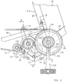
- a body frame 21A of an electric motor assist bicycle as a power assist vehicle includes a head pipe 22 mounted at the front end of the body frame 21A, a down pipe 23 extending rearwardly, downwardly from the head pipe 22, a supporting pipe 24 fixed at the rear end of the down pipe 23 and extending right and left, and a seat post 25 rising upwardly from the supporting pipe 24.
- a front fork 26 is steerably supported by the head pipe 22.
- a front wheel WF is rotatably supported by the lower ends of the front fork 26, and a steering handle 27 is provided at the upper end of the front fork 26.
- a rear wheel WR as a drive wheel is rotatably supported between the rear ends of a pair of right and left forked portions of a rear fork 28 extending rearwardly from the seat post 25 provided at the rear portion of the body frame 21A.
- a pair of right and left stays 29 are provided between the upper portion of the seat post 25 and both the forked portions of the rear fork 28.
- a supporting shaft 31 with a seat 30 on the upper end is mounted on the seat post 25 in such a manner as to allow adjustment of the vertical position of the seat 30.
- a battery containing box 32 for removably containing a battery (not shown) is provided on the front portion of the seat post 25 at a position lower than that of the seat 30.
- crank shaft 36 coaxially passes through the supporting pipe 24 of the body frame 21A.
- Crank pedals 37R and 37L are fixedly connected to the right and left ends of the crank shaft 36, respectively.
- Cover plates 38R and 38L are provided at the right and left ends of the supporting pipe 24, respectively, in such a manner as to cover the right and left ends of the supporting pipe 24 while allowing the crank shaft 36 to rotatably pass therethrough.
- a ball bearing 39 is provided between each of the cover plates 38R and 38L and the crank shaft 36. That is to say, the crank shaft 36 is rotatably supported by the body frame 21A.
- a power unit 35 having an electric motor 34 to which a power is supplied from a battery contained in the battery containing box 32 is disposed at the back of the supporting pipe 24.
- the power unit 35 is supported by the supporting pipe 24 and the right side forked portion of the rear fork 28.
- An actuation force of the crank pedals 37R and 37L provided at both the right and left ends of the crank shaft 36 is transmitted to a first rotating disk 40 in synchronization with rotation of the crank pedals 37R and 37L.
- a first one-way clutch 41 for cutting off torque transmission from the first rotating disk 40 to the right side crank pedal 37R is provided between the crank pedal 37R and the first rotating disk 40.
- the first one-way clutch 41 includes a clutch inner ring 42, a clutch outer ring 43, and a plurality, for example, three of rachet claws 44.
- the clutch inner ring 42 is integrally provided on the base end portion of the right side crank pedal 37R in such a manner as to coaxially surround the crank shaft 36.
- the clutch outer ring 43 is provided in such a manner as to coaxially surround the clutch inner ring 42.
- the rachet claws 44 are pivotably supported on the outer periphery of the clutch inner ring 42 and biased in the extension direction by an annular spring 45.
- Rachet teeth 46 with which the rachet claws 44 are to be engaged are formed on the inner periphery of the clutch outer ring 43.
- the inner periphery of the first rotating disk 40 is fixed on the outer periphery of the clutch outer ring 43.
- Such a first one-way clutch 41 functions as follows: namely, when the crank shaft 36 is normally rotated by actuating the crank pedals 37R and 37L, the actuation force of the crank pedals 37R and 37L is transmitted to the first rotating disk 40; while when the crank shaft 36 is reversely rotated by actuating the crank pedals 37R and 37L, the first one-way clutch 41 is slipped to allow reverse rotation of the crank shaft 36 and not to allow transmission of torque from the first rotating disk 40 to the crank pedal 37R side.
- a second rotating disk 48 which has a diameter larger than that of the first rotating disk 40, is disposed inside the first rotating disk 40 along the axial line of the crank shaft 36 in such a manner as to be adjacent to the first rotating disk 40 and to coaxially surround the crank shaft 36.
- the inner peripheral portion of the second rotating disk 48 is relatively rotatably disposed between the clutch inner ring 42 of the first one-way clutch 41 and a flange portion 50a of a cylindrical supporting member 50.
- the supporting member 50 is coupled, by thread-coupling or the like, to the inner periphery of the clutch inner ring 42 in such a manner as to relatively rotatably surround the crank shaft 36.
- a ring-like retaining plate 49 is disposed outside the first rotating disk 40 along the axial line of the crank shaft 36 in such a manner as to retain the outer peripheral portion of the first rotating disk 40 between the second rotating disk 48 and the same.
- Guide holes 51 are formed in the first rotating disk 40 at a plurality, for example, four of positions which are located near the outer periphery of the first rotating disk 40 in such a manner as to be spaced at equal intervals along the circumferential direction.
- Cylindrical collars 52 passing through the associated guide holes 51, are disposed between the second rotating disk 48 and retaining plate 49.
- the second rotating disk 48 and retaining plate 49 are connected to each other with rivets 53 passing through the associated collars 52. Accordingly, the second rotating disk 48 and retaining plate 49 can be rotated relative to the first rotating disk 40 in such a range that the collars 52 are movable in the guide holes 51.
- Rust-prevention films (not shown) for preventing occurrence of rust are stuck on facing planes of the first rotating disk 40 and each of the second rotating disk 48 and retaining plate 49.
- First containing holes 54 each of which is elongated relatively longer in the circumferential direction of the first rotating disk 40, are provided in the first rotating disk 40 at a plurality, for example, six of positions spaced at intervals in the circumferential direction of the first rotating disk 40.
- First restricting holes 55 and 56 corresponding to the first containing holes 54 of the first rotating disk 40 are also provided in the second rotating disk 48 and retaining plate 49, respectively.
- Coil springs 57 are each contained in a space formed by one of the first containing holes 54 and the associated first restricting holes 55 and 56.
- both ends of each coil spring 57 are in contact with both ends of each of the associated first containing hole 54 and first restricting holes 55 and 56.
- an operational force supplied from the crank pedals 37R and 37L is inputted into the first rotating disk 40 and the first rotating disk 40 is rotated relative to the second rotating disk 48 and retaining plate 49 in the direction shown by an arrow 58 in Fig. 6, one end of each coil spring 57 is left in contact with one end of the associated first containing hole 54, but the other end thereof is pushed by the other end of each of the associated first restricting holes 55 and 56 and is separated from the other end of the associated first containing hole 54. That is to say, the first rotating disk 40 is rotated relative to the second rotating disk 48 and retaining plate 49 while compressing the coil springs 57.
- the second rotating disk 48 is provided with pairs of holding walls 55a, each pair extending obliquely from both side edges of each first restricting hole 55 substantially along the outer periphery of the associated coil spring 57; while the retaining plate 49 is provided with pairs of holding walls 56a, each pair extending obliquely from both side edges of each first restricting hole 56 substantially along the outer periphery of the associated coil spring 57.
- second containing holes 60 are provided in the first rotating disk 40 at a plurality, for example, two of positions spaced 180° in the circumferential direction of the first rotating disk 40.
- Second restricting holes 61 and 62 corresponding to the second containing holes 60 are provided in the second rotating disk 48 and restricting plate 49, respectively.
- Coil-like counter springs 63 are each contained in a space formed by one of the second containing holes 60 and the associated second restricting holes 61 and 62.
- the second restricting holes 61 and 62 are offset from the second containing holes 60 in the circumferential direction of the first rotating disk 40, so that each counter spring 63 is contracted between one-sided end of the associated second containing hole 60 and the other-sided ends of the associated second restricting holes 61 and 62.
- the counter springs 63 exhibit spring forces biasing the first rotating disk 40 in the direction reversed to that shown by the arrow 58 in Fig. 6, and as the first rotating disk 40 is rotated relative to the second rotating disk 48 and retaining plate 49 in the direction shown by the arrow 58, the spring loads of the counter springs 63 become small.
- the counter springs 63 act to make constant an operational input into the first rotating disk 40 when the first rotating disk 40 starts to be rotated relative to the second rotating disk 48 and retaining plate 49 in the direction shown by the arrow 58.
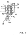
- the first rotating disk 40 and retaining plate 49 are covered with a cover 64 which is joined to the inner peripheral portion of the retaining plate 49 with a plurality, for example, four of clips 67.
- a lip portion 65a provided on the outer peripheral side of an annular elastic sealing member 65 mounted on the clutch outer ring 43 of the first one-way clutch 41 is elastically in contact with the inner surface of the inner peripheral portion of the cover 64, and a lip portion 65b provided on the inner peripheral side of the elastic sealing member 65 is elastically in contact with the clutch inner ring 42.
- a space formed between the clutch inner ring 42 and clutch outer ring 43 of the first one-way clutch 41 is filled with grease 66 and is sealed with the lip portion 65b.
- a pedal sprocket 68 is provided on the outer periphery of the second rotating disk 48 projecting outwardly from the cover 64.
- An endless chain 71 is wound around the pedal sprocket 68, a drive sprocket 69 driven by the power unit 35, and a driven sprocket 70 provided on the axle of the rear wheel WR.
- a sprocket 73 of a tensioner 72 for imparting a tensile force to the chain 71 meshes with the chain 71 at a position between the drive sprocket 69 and driven sprocket 70.
- the actuation force of the crank pedals 37R and 37L which has been transmitted to the first rotating disk 40 via the first one-way clutch 41, is transmitted to the second rotating disk 48, that is, the pedal sprocket 68 while compressing the coil springs 57, and is further transmitted to the rear wheel WR via the chain 71 and driven sprocket 70.
- an assist power supplied from the power unit 35 to the drive sprocket 69 is transmitted to the rear wheel WR via the chain 71 and driven sprocket 70.
- a torque due to the assist power supplied from the power unit 35 is not transmitted to the crank pedals 37R and 37L by the action of the first one-way clutch 41.
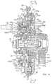
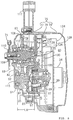
- a casing 75 of the power unit 35 includes a left casing half 76 as a first casing half, a right casing half 77 as a second casing half, and a cover 78.
- the right casing half 77 is joined to the left casing half 76 with a first containing chamber 79 put therebetween.
- the cover 78 is joined to the left casing half 76 with a second containing chamber 80 put therebetween.
- the second containing chamber 80 contains the electric motor 34 having a rotational axial line parallel to that of the crank shaft 36.
- the electric motor 34 is fixedly supported by the left casing half 76.
- the output of the electric motor 34 is transmitted to the drive sprocket 69 via a reduction roller type speed reducer 81, a reduction gear train 82 and a second one-way clutch 83 in order to assist the actuation force of the crank pedals 37R and 37L.
- the reduction roller type speed reducer 81 includes a motor shaft 84 of the electric motor 34, a bowl-like outer ring 85 surrounding the motor shaft 84, and a plurality, for example, three of reduction rollers 86, 87 and 88 rolling in contact with both the outer surface of the motor shaft 84 and inner surface of the outer ring 85.
- the speed reducer 81 has a function of speed-reducing an assist power generated by the electric motor 34 without occurrence of noise and transmitting the assist power thus speed-reduced onto the reduction gear train 82 side.
- the motor shaft 84 is rotatably supported by a cylindrical first bearing portion 89 provided on the left casing half 76 via a ball bearing 90, and the end portion of the motor shaft 84 projects from the second containing chamber 80 onto the first containing chamber 79 side.
- the outer ring 85 is disposed in the first containing chamber 79 in such a manner as to surround the end portion of the motor shaft 84 projecting onto the first containing chamber 79 side.
- the base end portion of an output shaft 115 is coaxially fixed at the center of the closed end portion of the bowl-like outer ring 85.
- a cylindrical second bearing portion 91 corresponding to the leading end of the output shaft 115 is provided on the right casing half 77, and the leading end of the output shaft 115 is rotatably supported by the second bearing portion 91 via a ball bearing 92.
- the reduction rollers 86, 87 and 88 are rotatably supported by roller shafts 93, 94 and 95 via needle bearings 96, 97 and 98, respectively.
- One-ends of the roller shafts 93 to 95 are supported by the left casing half 77, and the other ends of the roller shafts 93 to 95 are supported by a supporting plate 99.
- the supporting plate 99 is fastened, by means of screw members 101, to boss portions 100 each of which is integrally provided on the left casing half 77 at a position between two adjacent ones of the reduction rollers 86, 87 and 88.
- each of the reduction rollers 86 and 87 is supported by the left casing half 77 and supporting plate 99 in such a manner that the contact position of each of the reduction rollers 86 and 87 with the motor shaft 84 along the circumferential direction of the motor shaft 84 is kept fixed.
- Fitting holes 102 with their bottoms closed, to each of which one end of the associated one of the roller shafts 93 and 94 of the reduction rollers 86 and 87 is to be fitted, are provided in the left casing half 77.
- the reduction roller 88 is supported by the left casing half 77 and supporting plate 99 in such a manner that the contact position of the reduction roller 88 with the motor shaft 84 along the circumferential direction of the motor shaft 84 is made variable within an allowable range in order for the reduction roller 88 to be moved and bitten between the motor shaft 84 and outer ring 85 by frictional engagement with the motor shaft 84 upon rotation of the motor shaft 84.
- the fitting hole 103 is elongated substantially along the circumferential direction of the motor shaft 84.
- one end of a pressing pin 104 is in contact with the side surface of the roller shaft 95.
- a spring 105 for biasing the pressing pin 104 in the direction of bringing the pressing pin 104 into contact with the roller shaft 95 is provided between the pressing pin 104 and the left casing half 77.
- the reduction roller 88 is biased by the spring force of the spring 105 in the direction in which such a reduction roller 88 is bitten between the motor shaft 84 and outer ring 85.
- the outside diameters of the reduction rollers 86 and 88 are identical to each other, while the outside diameter of the reduction roller 87 is larger than that of each of the reduction rollers 86 and 88. Accordingly, the axial line of the output shaft 115 is eccentric to the axial line of the motor shaft 84.
- the reduction roller type speed reducer 81 having the above configuration, when the motor shaft 84 is rotated in the direction shown by an arrow 106 in Fig. 9 by operation of the electric motor 34, the reduction roller 88 is bitten between the motor shaft 84 and outer ring 85 to thus exhibit the wedge action. As a result, the contact surface pressures between the reduction rollers 86 to 88 and the motor shaft 84 and between the reduction rollers 86 to 88 and the outer ring 85 are increased, so that the output torque from the motor 34 is transmitted from the motor shaft 84 to the output shaft 115 via the reduction rollers 86 to 88 and the outer ring 85.
- the periphery of the motor shaft 84 is restricted in the three directions by the reduction rollers 86 to 88, so that a force proportional to the drive torque of the electric motor 34 acts between the reduction rollers 86 to 88 and the motor shaft 84, whereby vibration caused by the electric motor 34 can be damped by the reduction roller type speed reducer 81.
- the reduction gear train 82 is composed of a drive gear 107 as a power transmitting portion, and a driven gear 108 meshing with the drive gear 107.
- the drive gear 107 is integrally provided on the output shaft 115 at a position between the second bearing portion 91 of the right casing half 77 and the outer ring 85.
- the motor shaft 84 is supported by the first bearing portion 89 of the left casing half 76 via the ball bearing 90, while the output shaft 115 is supported in a cantilever manner by the second bearing portion 91 of the right casing half 77 via the ball bearing 92.
- a length LA from the center of the ball bearing 90 to the axial center of each of the reduction rollers 86 to 88 is set to be larger than twice an outside diameter DA of a portion, in contact with each of the reduction rollers 86 to 88, of the motor shaft 84 ( LA>DA ⁇ 2 ), and a length LB from the axial center of each of the reduction rollers 86 to 88 to the axial center of the ball bearing 92 is set to be larger than half an inside diameter DB of the outer ring 85 ( LB>DB ⁇ 1/2 ).
- the supporting length from the ball bearing 90 to the motor shaft 84 and the cantilever-supporting length from the ball bearing 92 to the output shaft 115 can be each suitably set so that the effect of the above relatively rough assembly is minimized at the meshing portion between the drive gear 107 of the output shaft 115 and the driven gear 108.
- the driven gear 108 of the reduction gear train 82 is disposed in such a manner as to coaxially surround a rotational drive shaft 109.
- the rotational drive shaft 109 is rotatably supported by the right casing half 77 via a ball bearing 110 and also rotatably supported by the left casing half 76 via a ball bearing 111.
- the drive sprocket 69 is fixed at the end portion, projecting from the right casing half 77, of the rotational drive shaft 109.
- a ball bearing 112 and the second one-way clutch 83 are provided between the rotational drive shaft 109 and driven gear 108.
- the second one-way clutch 83 has a clutch outer ring 113 integrally provided on the driven gear 108 and a clutch inner ring 114 integrally provided on the rotational drive shaft 109.
- the configuration of the second one-way clutch 83 is the same as that of the first one-way clutch 41.
- the second one-way clutch 83 allows transmission of a torque, which has been generated by operation of the electric motor 34 and speed-reduced by the reduction roller type speed reducer 81 and reduction gear train 82, to the rotational drive shaft 109, that is, the drive sprocket 69; while it allows, when the operation of the electric motor 34 is stopped, idling of the rotational drive shaft 109 in order not to obstruct the rotation of the drive sprocket 69 by the actuation force of the crank pedals 37R and 37L.
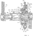
- the casing 75 is supported by the supporting pipe 24 of the body frame 21A and the right side forked portion of the rear fork 28 in such a manner that the electric motor 34 is disposed behind, under the crank shaft 36.
- a hanger portion 117 provided on the casing 75 is fastened to a bracket 116 fixed on the right side forked portion of the rear fork 28, and a hanger portion 119 provided on the casing 75 is fastened to a bracket 118 fixed on the supporting pipe 24.
- the tensioner 72 for stretching the chain 71 is mounted on the casing 75 at a position offset reawardly, obliquely downwardly from the drive sprocket 69.
- the tensioner 72 includes a lever 122, the sprocket 73, and a spring 123.
- the lever 122 is supported at its base end portion by the casing 75 in such a manner as to be swingable around the axial line parallel to the drive sprocket 69.
- the sprocket 73 is rotatably supported at the leading end of the lever 122.
- the spring 123 is adapted to bias the lever 122 in the direction of stretching the chain 71 meshing with the sprocket 73.
- a control unit 124 is contained in the second containing chamber 80 at the side of the electric motor 34.
- the control unit 124 includes an aluminum board 125 mounted on the left casing half 76; a printed wiring board 126 mounted on the left casing half 76 with a gap put between the aluminum board 125 and the same; a FET 127 and the like arranged on the aluminum board 125; and a capacitor 128, a relay 129, a CPU 130, and the like arranged on the printed wiring board 126.
- the operation of the electric motor 34 is controlled by the control unit 124.
- a first magnetic ring 131 rotating with the first rotating disk 40 is disposed opposite to the first rotating disk 40 with respect to the second rotating disk 48, and a second magnetic ring 132 rotating with the second rotating disk 48 is disposed at a position where the first magnetic ring 131 is put between the second magnetic ring 132 and the second rotating disk 48. That is to say, the first and second magnetic rings 131 and 132 are axially arranged on one side of the first and second rotating disks 40 and 48 in the axial direction.
- the first magnetic ring 131 is formed by providing a plurality of N-poles 131N and a plurality of S-poles 131S, which are alternately, adjacently arranged in the circumferential direction into a ring shape, on an elastically deformable first retaining member 133 made from a synthetic resin or the like.
- 60 pieces of the N-poles 131N and 60 pieces of the S-poles 131S are alternately arranged on the first retaining member 133 with a center angle of 3° set between one N-pole 131N and the adjacent S-pole 131S.
- the first retaining member 133 includes a cylindrical supporting portion 133a on the inner periphery of which the N-poles 131N and S-poles 131S are provided, and a pair of engagement claws 133b extending from the supporting portion 133a onto the first rotating disk 40 side. Both the engagement claws 133b are formed so as to be branched in the circumferential direction of the supporting portion 133a and are disposed along one diameter line of the supporting portion 133a.
- Through-holes 134 are provided in the second rotating disk 48 adjacent to the first magnetic ring 131 at a plurality, for example, four of positions spaced at equal intervals in the circumferential direction of the second rotating disk 48.
- a synthetic resin made intermediate coupling member 136 shown in Fig. 12 is disposed inwardly from the retaining plate 49 at a position between the first rotating disk 40 and cover 64.
- the intermediate coupling member 136 integrally includes a ring portion 136a disposed in such a manner as to surround the elastic sealing member 65, a pair of first lugs 136b projecting outwardly from the outer periphery of the ring portion 136a along one diameter line of the ring portion 136a, and a pair of second lugs 136c projecting outwardly from the outer periphery of the ring portion 136a along another diameter line perpendicular to the above diameter line along which the first lugs 136b are disposed.
- the first lugs 135b have engagement holes 137 into which the engagement claws 133b projecting through the though-holes 135 of the first rotating disk 40 are to be elastically engaged.
- the second lugs 136c are integrally provided with two engagement claws 138 branched in the circumferential direction of the ring portion 136a, which engagement claws project onto the first rotating disk 40 side. Engagement holes 139 into which the engagement claws 138 are to be elastically engaged are provided in the first rotating disk 40.
- the engagement claws 133b of the first retaining member 133 and the engagement claws 138 of the intermediate coupling member 136 are flexible because each of the first retaining member 133 and intermediate coupling member 136 is made from a synthetic resin.
- the intermediate coupling member 136 is coupled to the first rotating disk 40 in such a manner as to be movable in an allowable range in the direction along one diameter line of the first rotating disk 40, and the first retaining member 133 of the first magnetic ring 131 is coupled to the intermediate coupling member 136 in such a manner as to be movable in an allowable range in the direction perpendicular to the above diameter line. That is to say, the intermediate coupling member 136 couples the first rotating disk 40 to the first retaining member 133 in an Oldham' coupling manner.
- the through-holes 134 provided in the second rotating disk 48 are elongated relatively longer in the circumferential direction of the second rotating disk 48 so that the engagement claws 133b are not brought into contact with both sides of the through-holes 134 in the circumferential direction when the first and second rotating disks 40 and 48 are relatively rotated.
- the second magnetic ring 132 is formed by providing a plurality of N-poles 132N and a plurality of S-poles 132S, which are alternately, adjacently arranged in the circumferential direction into a ring shape, on an elastically deformable second retaining member 140 made from a synthetic resin or the like.
- the N-poles 132N and S-poles 132S are alternately arranged on the second retaining member 140 with the same center angle as that for the N-poles 131N and S-poles 131S of the first magnetic ring 131 set between one N-pole 132N and the adjacent S-pole 132S.
- the second retaining member 140 integrally includes a cylindrical supporting portion 140a; a cover portion 140b; a plurality, for example, four of contact legs 140c; and two engagement claws 140d.
- the supporting portion 140a has the N-poles 132N and S-poles 132S provided on the inner periphery thereof.
- the cover portion 140b projects radially outwardly from the supporting portion 140a in such a manner as to cover the portions corresponding to the restricting holes 55 of the second rotating disk 48 on the side opposed to the first rotating disk 40.
- the contact legs 140c project from the cover portion 140b in such a manner as to be brought into contact with the second rotating disk 48.
- the engagement claws 140d are provided on the cover portion 140b at four positions spaced at equal intervals in the circumferential direction in such a manner as to project from the cover portion 140b onto the second rotating disk 48 side.
- engagement holes 141 into which the engagement claws 140d are to be elastically engaged are provided in the second rotating disk 48 at a plurality, for example, four of positions spaced in the circumferential direction, and the second retaining member 140 of the second magnetic ring 132 is elastically engaged with the second rotating disk 48. Openings 142 in which the end portions of the engagement claws 140d engaged in the engagement holes 141 are to be located are provided in the first rotating disk 40.
- each of the openings 142 is elongated relatively longer in the circumferential direction of the first rotating disk 40 so that the associated engagement claw 140d is not brought into contact with both sides of the opening 142 in the circumferential direction when the first and second rotating disks 40 and 48 are relatively rotated.
- a circular recess 143 is provided in an inner peripheral portion, on the second rotating disk 48 side, of the supporting portion 140a of the second retaining member 140, and the supporting portion 133a of the first retaining member 133 is inserted in the recess 143.
- Projections 144 to be in slide-contact with the inner surface of the recess 143 are integrally provided on the outer surface of the supporting portion 133a of the first retaining member 133 at a plurality, for example, four of positions spaced at equal intervals in the circumferential direction.
- the outer periphery of the supporting portion 133a of the first retaining member 133 is in contact with the inner periphery of the supporting portion 140a of the second retaining member 140 at the plurality of positions spaced in the circumferential direction.
- first sensors 145A for detecting the N-poles 131N and S-poles 131S provided on the inner periphery of the first magnetic ring 131 are provided at a plurality, for example, four of positions spaced at equal intervals in the circumferential direction, and a single first sensor 145B for detecting the N-poles 131N and S-poles 131S is disposed in such a manner as to be spaced 180° from one of the first sensors 145A in the circumferential direction.
- second sensors 146A for detecting the N-poles 132N and S-poles 132S provided on the inner periphery of the second magnetic ring 132 are provided at a plurality, for example, four of positions spaced at equal intervals in the circumferential direction, and a single second sensor 146B for detecting the N-poles 132N and S-poles 132S is disposed in such a manner as to be spaced 180° from one of the second sensors 146A in the circumferential direction.
- first and second sensors 145A, 145B, 146A and 146B there may be any sensor for detecting a magnetic pole, for example, a Hall element or MR element.
- the first sensors 145A and 145B and second sensors 146A and 146B are buried in a base member 147 made from a synthetic resin, and the base member 147 is supported by the supporting pipe 24 of the body frame 21A.
- a supporting plate 149 having the outer periphery which is brought into contact with and engaged with the inner periphery of the first retaining member 131, is mounted on the base member 147. The supporting plate 149 prevents movement of the first retaining member 131 onto the second rotating disk 48 side.
- each first sensor 145A outputs a high level signal upon detection of the N-pole 131N.
- the first sensors 145A (No. 1 to No. 4) output signals shown in Fig. 15 for each of the stages ST1 to ST8.
- the combination of the output signals from the first sensors 145A is [1111] in binary form (OF in hexadecimal form); at the second stage ST2, the combination of the output signals from the first sensors 145A is [1110] in binary form (OE in hexadecimal form); at the third stage ST3, the combination of the output signals from the first sensors 145A is [1100] in binary form (OC in hexadecimal form); at the fourth stage ST4, the combination of the output signals from the first sensors 145A is [1000] in binary form (08 in hexadecimal form); at the fifth stage ST5, the combination of the output signals form the first sensors 145A is [0000] in binary form (00 in hexadecimal form); at the sixth stage ST6, the combination of the output signals from the first sensors 145A is [0001] in binary form (01 in hexadecimal form
- the second sensors 146A are buried in the base member 147 in such a manner that the relative positional relationship between the second sensors 146A and the N-poles 132N and S-poles 132S of the second magnetic ring 132 is the same as the relative positional relationship between the first sensors 145A and the N-poles 131N and S-poles 131S of the first magnetic ring 131.
- the combination pattern of signals detected by four of the second sensors 146A differs for each angular displacement changed from the first to eighth stages ST1 to ST8.
- the signals detected by the first and second sensors 145A and 146A are inputted in the control unit 124, and the control unit 124 controls the operation of the electric motor 34 on the basis of the signals detected by the first and second sensors 145A and 146A in accordance with a control procedure shown in Fig. 16.
- a vehicular speed is first calculated at Step S1.
- Step S2 it is decided whether or not the vehicular speed is a setting vehicular speed VS or more.
- the vehicular speed VS for decision criterion is previously set at a value near [0], for example, in a range of 0.5 to 1 km/h in order to decide whether or not the electric power assist bicycle is substantially in the stoppage state before running upon start of actuation of the crank pedals 37R and 37L. If it is decided that the vehicular speed is less than the setting vehicular speed VS, that is, the crank pedals 37R and 37L start to be actuated, the process goes on to Step S3.
- Step S3 the outputs of four of the first sensors 145A are read, and at Step S4, the detection pattern of four of the first sensors 145A is calculated. Then, at Step S5, the outputs of four of the second sensors 146A are read, and at Step S6, the detection pattern of four of the second sensors 146A is calculated.
- Step S7 a phase difference between the first and second magnetic rings 131 and 132, that is, a rotational phase difference between the first and second rotating disks 40 and 48 is calculated by the combination of the detection patterns of the first sensors 145A and second sensors 146A.
- the output signals from the first sensors 145A (No. 1 to No. 4) and the output signals from the second sensors 146A (No. 1 to No. 4) obtained in a state in which a rotational phase difference occurs between both the rotating disks 40 and 48 depending on the inputted torque are as shown in Fig. 17.
- the detection pattern of the first sensors 145A is [0E] (hexadecimal form) while the detection pattern of the second sensors 146A is [07] (hexadecimal form).
- the detection pattern of the first sensors 145A is [00] (hexadecimal form) while the detection pattern of the second sensors 146A is [08] (hexadecimal form).
- Step S7 when a torque being in a range of one-eighth to two-eighth the detectable maximum torque is inputted, at Step S7, a rotational phase difference equivalent to an angular displacement of one stage or two stages is obtained in digital form at a selected detection timing by the combination of the detection patterns of the first sensors 145A and second sensors 146A. Then, at Step S8, an input torque is obtained by multiplying the above rotational phase difference by the spring constant of the coil springs 57 provided between the first and second rotating disks 40 and 48.
- Step S9 a motor control amount depending on the input torque obtained at Step S8 is determined.
- the duty control amount of the electric motor 34 is calculated at Step S9, and at Step S10, the control amount is outputted.
- Step S1 to S10 The procedure of Steps S1 to S10 is carried out for detection of an input torque upon start of actuation of the crank pedals 37R and 37L and for control of operation of the electric motor 34 based on the input torque thus detected.
- Step S2 if it is decided that the vehicular speed is equal to or more than the setting vehicular speed VS, the process is shifted from Step 2 to Step S11.
- Step S11 it is decided whether or not the output of No. 1 of four of the first sensors 145A becomes the high level. If YES, the counting by a timer starts at Step S12.
- Step S13 it is decided whether or not the output of No. 1 of four of the second sensors 146A becomes the high level. If YES, the count "t" by the timer is stored at Step S14. Then, at Step S15, it is decided whether or not the output of No. 1 of four of the first sensors 145A becomes the high level again. If YES, a count "T" by the timer is stored and the timer is reset at Step S16.
- the output of the first sensor 145A (No. 1) is, for example, as shown in Fig. 18(a) and the output of the second sensor 146A (No. 1) is, for example, as shown in Fig. 18(b).
- the count "t” designates a deviation in output between the first and second sensors 145A (No. 1) and 146A (No. 1)
- the count "T” designates a detection cycle of the first sensor 145A (No. 1).
- Step S17 t/T is calculated.
- a phase difference between the first and second magnetic rings 131 and 132 that is, a phase difference between the first and second rotating disks 40 and 48 is obtained as the analog value t/T at Step S17.
- a coupler portion 150 for taking out signals from the sensors 145A, 145B, 146A and 146B is integrally provided on the base member 147.
- a labyrinth structure 151 is provided between the first and second magnetic rings 131 and 132 and the base member 147.
- An annular sealing member 152 to be in slide-contact with the second magnetic ring 132 is provided on the base member 147, and an annular sealing member 153 to be slide-contact with the base member 147 is held between a cover plate 38R screwed in the right end of the supporting pipe 24 and the supporting pipe 24.
- the actuation force of the crank pedals 37R and 37L causes a rotational phase difference while compressing the coil springs 57 between the first and second rotating disks 40 and 48.
- the control unit 124 calculates an input torque on the basis of a combination of detection signals of a plurality of the first sensors 145A for detecting the N-poles 131N and S-poles 131S of the first magnetic ring 131 rotating with the first rotating disk 40 and detection signals of a plurality of the second sensors 146A for detecting the N-poles 132N and S-poles 132S of the second magnetic ring 132 rotating with the second rotating disk 48.
- the control unit 124 controls the electric motor 34 in such a manner that the electric motor 34 outputs an assist power based on the input torque, to control the rotational assist power of the drive sprocket 69, thereby reducing the load of the driver.
- the first rotating disk 40 causes a rotational phase difference with respect to the second rotating disk 48, so that the first magnetic ring 131 causes a rotational phase difference with respect to the second magnetic ring 132.
- the combination patterns of signals detected by the first sensors 145A and second sensors 146A are varied from those in the state before actuation of the crank pedals 37R and 37L, so that an input torque can be immediately detected at the initial stage of starting input operation in the stoppage state of the vehicle and thereby an assist power based on the input torque can be generated by the electric motor 34 and imparted to the rear wheel WR.
- an input torque is calculated on the basis of a rotational phase difference obtained in digital form; while in the usual running state of the electric power assist bicycle, an input torque is linearly calculated on the basis of a rotational phase difference obtained in analog form. Accordingly, an assist power linearly based on the input torque can be obtained by generating the assist power based on the linear input torque by the electric motor 34. In this way, in the entire region from the initial stage of actuating the crank pedals 37R and 37L to the usual running state, it is possible to certainly detect an input torque and to impart an assist power generated by the electric motor 34 to the rear wheel WR.
- the remaining portions, other than the mutual contact portions, of the first retaining member 133 and second retaining member 140 can be elastically deformed, to keep the concentricity between the first retaining member 133 and second retaining member 140.
- the friction of the first and second rotating disks 40 and 48 is increased because the axial deviation is corrected; however, since the first and second retaining members 133 and 140 are in contact with each other only at a plurality of positions spaced at intervals in the circumferential direction, it is possible to keep smooth rotation of both the rotating disks 40 and 48 by accurately finishing only the mutual contact portions of both the retaining members 133 and 140. As a result, even if an axial deviation occurs between both the rotating disks 40 and 48, the adverse effect of the axial deviation is prevented from being exerted on the detection value of the input torque as much as possible, and thereby the input torque can be more accurately detected.
- the intermediate coupling member 135 is coupled to the first rotating disk 40 in such a manner as to be movable in an allowable range in the direction along one diameter line of the first rotating disk 40 and the first magnetic ring 131 is coupled to the intermediate coupling member 135 in such a manner as to be movable in an allowable range in the direction perpendicular to the above one diameter line, the intermediate coupling member 135 functions as the Oldham's coupling. Accordingly, even if an axial deviation occurs between both the first and second rotating disks 40 and 48, it is possible to prevent an excess load from being applied to the first and second retaining members 133 and 140.
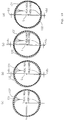
- the single first sensor 145B is disposed in such a manner as to be spaced 180° from one of the first sensors 145A in the circumferential direction; while four of the second sensors 146A, facing to the second magnetic ring 132, are spaced at equal intervals in the circumferential direction, and the single second sensor 146B is disposed in such a manner as to be spaced 180° from one of the second sensors 146A in the circumferential direction.
- the absolute value of a delay - ⁇ b of the phase detected by the one of the first sensors 145A (or second sensors 146A) is equal to the absolute value of an advance + ⁇ b of the phase detected by the single first sensor 145B (or single second sensor 146B). As shown in Fig.
- the absolute value of a delay - ⁇ c of the phase detected by the one of the first sensors 145A (or second sensors 146A) is equal to the absolute value of an advance + ⁇ c of the phase detected by the single first sensor 145B (or single second sensor 146B). As shown in Fig.
- the absolute value of a delay - ⁇ d of the phase detected by the one of the first sensors 145A (or second sensors 146A) is equal to the absolute value of an advance + ⁇ d of the phase detected by the single first sensor 145B (or single second sensor 146B).
- a phase difference between both the magnetic rings 131 and 132 can be accurately detected by halving the sum of a phase detected by one of four of the first sensors 145A (or second sensors 146A) and a phase detected by the single first sensor 145B (or single second sensor 146B), and an input torque can be accurately detected on the basis of the phase difference thus obtained.
- Such drive of the electric motor 34 using the rotational phase difference alternately changed with an elapsed time is equivalent to the drive of the electric motor 34 using a rotational phase difference obtained by the above method of halving the sum of a phase detected by the one first sensors 145A (or second sensors 146A) and a phase detected by the single first sensor 145B (or single second sensor 146B), to thereby make it possible to obtain an assist power accurately based on an input torque.
- the reduction roller type speed reducer 81 for transmitting a power supplied from the electric motor 34 onto the reduction gear train 82 side includes the motor shaft 84 connected to the electric motor 34, a plurality of the reduction rollers 86, 87 and 88 in rolling-contact with the outer surface of the motor shaft 84, and the outer ring 85 having the inner surface with which the reduction rollers 86 to 88 are in rolling-contact.
- the motor shaft 84 of the electric motor 34 mounted on the outer surface side of the left casing half 76 is supported by the first bearing portion 89 provided on the left casing half 76 via the bearing 90; the roller shafts 93, 94 and 95 for rotatably supporting the reduction rollers 86 to 88 respectively are supported by the left casing half 76; and the leading end of the output shaft 115 with its based end portion fixed at the central portion of the closed end of the outer ring 85 is supported in a cantilever manner by the second bearing portion 91 provided on the right casing half 77 via the ball bearing 92; and the drive gear 107 for transmitting a power supplied from the output shaft 115 onto the rotational drive shaft 109 side is provided on the output shaft 115 at a position between the outer ring 85 and the second bearing portion 91.
- the motor shaft 84 is supported by the first bearing portion 89 of the left casing half 76; the output shaft 115 is supported in a cantilever manner by the second bearing portion 91 of the right casing half 77; and the drive gear 107 is provided on the output shaft 115 between the outer ring 85 and the second bearing portion 91, so that the length between the outer ring 85 and second bearing portion 91, that is, the cantilever-supporting length of the output shaft 115 is made longer.
- the present invention can be applied not only to an electric power assist bicycle but also to a motor-driven wheelchair and the like.
- the invention provides an assist power transmission apparatus for a power assist vehicle including a reduction roller type speed reducer provided between an electric motor and a rotational drive shaft for imparting a rotational power to a drive wheel, which is capable of desirably assembling the reduction roller type speed reducer at a relatively rough assembling accuracy, thereby improving the productivity.
- first and second casing halves 76, 77 are connected to each other with a containing chamber 79 put therebetween.
- a motor shaft 84 of an electric motor 34 mounted on the outer surface side of the first casing half 76 is rotatably supported by a first bearing portion 89 provided on the first casing half 76.
- Reduction rollers 86, 87 and 88 are rotatably supported on the first casing half 76.
- An output shaft 115 with its base end portion fixed at the central portion of a closed end of a bowl-like outer ring 85 is rotatably supported by a second bearing portion 91 provided on the second casing half 77.
- a power transmission portion 107 is provided on the output shaft 115 at a position between the outer ring 85 and second bearing portion 91.
Landscapes
- Engineering & Computer Science (AREA)
- Chemical & Material Sciences (AREA)
- Combustion & Propulsion (AREA)
- Transportation (AREA)
- Mechanical Engineering (AREA)
- Connection Of Motors, Electrical Generators, Mechanical Devices, And The Like (AREA)
- Friction Gearing (AREA)
Abstract
To achieve this, first and second casing halves 76, 77 are connected to each other with a containing chamber 79 put therebetween. A motor shaft 84 of an electric motor 34 mounted on the outer surface side of the first casing half 76 is rotatably supported by a first bearing portion 89 provided on the first casing half 76. Reduction rollers 86, 87 and 88 are rotatably supported on the first casing half 76. The leading end of an output shaft 115 with its base end portion fixed at the central portion of a closed end of a bowl-like outer ring 85 is rotatably supported by a second bearing portion 91 provided on the second casing half 77. A power transmission portion 107 is provided on the output shaft 115 at a position between the outer ring 85 and second bearing portion 91.
Description
- The present invention relates to an assist power transmission apparatus for a power assist vehicle in which a reduction roller type speed reducer is provided between an electric motor mounted in a casing supported by a body frame and a rotational drive shaft for imparting a rotational power to a drive wheel, wherein the reduction roller type speed reducer includes a motor shaft connected to the electric motor, a plurality of reduction rollers rotating in contact with the outer surface of the motor shaft, and an outer ring having the inner peripheral surface being in rolling-contact with the reduction rollers.
- Conventionally, such an assist power transmission apparatus has been already known, for example, from Japanese Patent Laid-open No. Hei 7-95744. In this apparatus, an electric motor is mounted to a casing in such a manner as to cover the opened end portion of the casing; a reduction roller type speed reducer is contained in the casing in such a manner as to be entirely covered with the casing; an outer ring of the reduction roller type speed reducer is fixed on the casing; carriers for supporting a plurality of reduction rollers rotating in contact with the outer peripheral surface of a motor shaft and the inner peripheral surface of the outer ring are connected via a one-way clutch to one end portion of an output shaft having an intermediate portion rotatably supported by the casing; and a gear for transmitting a power to the rotational drive shaft side is provided on the other end portion of the output shaft.
- In the above-described prior art reduction type speed reducer, it is necessary for the reduction rollers to be rotated in a state being certainly in contact with the outer surface of the motor shaft and the inner surface of the outer ring. In this regard, according to the above prior art speed reducer, since the electric motor is mounted on the casing; the outer ring is fixed on the casing; and the carriers for supporting the reduction rollers are supported, via the one-way clutch, by the output shaft rotatably supported by the casing at a position relatively closer to the reduction rollers, it is required to assemble the electric motor, outer ring and carriers in the casing at high assembling accuracies, thereby making poor the productivity.
- In view of the foregoing, the present invention has been made, and an object of the present invention is to provide an assist power transmission apparatus for a power assist vehicle, which is capable of desirably assembling a reduction roller type speed reducer for transmitting an assist power from an electric motor at a relatively rough assembling accuracy, thereby improving the productivity.
- To achieve the above object, according to an invention described in
claim 1, there is provided an assist power transmission apparatus for a power assist vehicle in which a reduction roller type speed reducer is provided between an electric motor mounted to a casing supported by a body frame and a rotational drive shaft for imparting a rotational power to a drive wheel, the reduction roller type speed reducer including a motor shaft connected to the electric motor, a plurality of reduction rollers rotating in contact with the outer surface of the motor shaft, and an outer ring having the inner peripheral surface with which the reduction rollers are in rolling-contact, characterized in that first and second casing halves constituting at least part of the casing are connected to each other with a containing chamber put therebetween; the motor shaft of the electric motor mounted on the outer surface side of the first casing half projects in the containing chamber while being rotatably supported by a first bearing portion provided on the first casing half; roller shafts for rotatably supporting the reduction rollers are supported by the first casing half; the leading end of an output shaft with its base end portion fixed at the central portion of a closed end of the bowl-like outer ring opened toward the first casing half side is rotatably supported by a second bearing portion provided on the second casing half; and a power transmission portion for transmitting a power from the output shaft to the rotational drive shaft side is provided on the output shaft at a position between the outer ring and the second bearing portion. - With this configuration, the motor shaft of the reduction roller type speed reducer is supported by the first bearing portion of the first casing half, and the output shaft is supported in a cantilever manner by the second bearing portion of the second casing half. Further, since the power transmission portion is provided on the output shaft at a position between the outer ring and the second bearing portion, the length between the outer ring and the second bearing portion, that is, the cantilever supporting length of the output shaft is made longer. As a result, even if the electric motor, outer ring and reduction rollers are assembled in the casing at relatively rough assembling accuracies, the motor shaft and the output shaft being made large in axial length and supported in a cantilever manner can be slightly deflected, to allow the reduction rollers to be certainly in rolling-contact with the motor shaft and outer ring, thereby improving the productivity.
- According to an embodiment described in claim 2, the length from the axial center of the first bearing portion to the axial center of each of the reduction rollers is set to be larger than twice the outside diameter of a portion, in contact with the reduction rollers, of the motor shaft; and the length from the axial center of each of the reduction rollers to the axial center of the second bearing portion is set to be larger than half the inside diameter of the outer ring. With this configuration, even if the rollers of the reduction roller type speed reducer and the motor shaft are assembled in the casing at relatively rough assembling accuracies, the supporting length of the motor shaft and the cantilever supporting length of the output shaft can be both suitably set so that the influence of the rough assembling accuracies is minimized at the connecting portion between the output shaft and the power transmission portion.
- As described above, according to the inventions described in
claims 1 and 2, even if the electric motor, outer ring and reduction rollers are assembled in the casing at relatively rough assembling accuracies, the motor shaft and the output shaft being made large in axial length and supported in a cantilever manner can be slightly deflected, to allow the reduction rollers to be certainly in rolling-contact with the motor shaft and outer ring, thereby improving the productivity. - Hereinafter, the mode for carrying out the present invention will be described by way of one embodiment of the present invention with reference to the accompanying drawings.
- Fig. 1 is a side view of an electric power assist vehicle;
- Fig. 2 is an enlarged view of an essential portion shown in Fig. 1;
- Fig. 3 is a sectional view taken on line 3-3 of Fig. 2;
- Fig. 4 is an enlarged view of an essential portion shown in Fig. 3;
- Fig. 5 is a sectional view taken on line 5-5 of Fig. 4;
- Fig. 6 is a sectional view taken on line 6-6 of Fig. 4;
- Fig. 7 is an enlarged sectional view taken on line 7-7 of Fig. 5;
- Fig. 8 is an enlarged sectional view taken on line 8-8 of Fig. 2;
- Fig. 9 is an enlarged sectional view taken on line 9-9 of Fig. 8;
- Fig. 10 is a sectional view taken on line 10-10 of Fig. 9;
- Fig. 11 is a sectional view taken on line 11-11 of Fig. 4;
- Fig. 12 is a front view of an intermediate coupling member;
- Fig. 13 is a sectional view taken on line 13-13 of Fig. 4;
- Fig. 14 is a diagram showing a relative arrangement between first sensors and magnetic poles of a first magnetic ring.
- Fig. 15 is a diagram illustrating a detection pattern of the first sensor depending on a change in circumferential position relative to the first magnetic ring.
- Fig. 16 is a flow chart showing a procedure of controlling an electric motor by a control unit;
- Fig. 17 is a diagram illustrating detection patterns of the first and second sensors depending on relative rotation of the first and second magnetic rings;
- Figs. 18a and 18b are diagrams illustrating detection of a phase difference in a usual running state; and
- Figs. 19a to 19d are diagrams illustrating an axial deviation between the first and second magnetic rings.
-
- Referring to Figs. 1 to 3, a
body frame 21A of an electric motor assist bicycle as a power assist vehicle includes ahead pipe 22 mounted at the front end of thebody frame 21A, adown pipe 23 extending rearwardly, downwardly from thehead pipe 22, a supportingpipe 24 fixed at the rear end of thedown pipe 23 and extending right and left, and aseat post 25 rising upwardly from the supportingpipe 24. - A
front fork 26 is steerably supported by thehead pipe 22. A front wheel WF is rotatably supported by the lower ends of thefront fork 26, and asteering handle 27 is provided at the upper end of thefront fork 26. A rear wheel WR as a drive wheel is rotatably supported between the rear ends of a pair of right and left forked portions of arear fork 28 extending rearwardly from the seat post 25 provided at the rear portion of thebody frame 21A. A pair of right andleft stays 29 are provided between the upper portion of theseat post 25 and both the forked portions of therear fork 28. - A supporting
shaft 31 with aseat 30 on the upper end is mounted on theseat post 25 in such a manner as to allow adjustment of the vertical position of theseat 30. Abattery containing box 32 for removably containing a battery (not shown) is provided on the front portion of theseat post 25 at a position lower than that of theseat 30. - A
crank shaft 36 coaxially passes through the supportingpipe 24 of thebody frame 21A.Crank pedals crank shaft 36, respectively.Cover plates pipe 24, respectively, in such a manner as to cover the right and left ends of the supportingpipe 24 while allowing thecrank shaft 36 to rotatably pass therethrough. A ball bearing 39 is provided between each of thecover plates crank shaft 36. That is to say, thecrank shaft 36 is rotatably supported by thebody frame 21A. - A
power unit 35 having anelectric motor 34 to which a power is supplied from a battery contained in thebattery containing box 32 is disposed at the back of the supportingpipe 24. Thepower unit 35 is supported by the supportingpipe 24 and the right side forked portion of therear fork 28. - An actuation force of the
crank pedals crank shaft 36 is transmitted to a first rotatingdisk 40 in synchronization with rotation of thecrank pedals way clutch 41 for cutting off torque transmission from the first rotatingdisk 40 to the rightside crank pedal 37R is provided between thecrank pedal 37R and the first rotatingdisk 40. - Referring to Figs. 4 to 6, the first one-
way clutch 41 includes a clutchinner ring 42, a clutchouter ring 43, and a plurality, for example, three ofrachet claws 44. The clutchinner ring 42 is integrally provided on the base end portion of the rightside crank pedal 37R in such a manner as to coaxially surround thecrank shaft 36. The clutchouter ring 43 is provided in such a manner as to coaxially surround the clutchinner ring 42. Therachet claws 44 are pivotably supported on the outer periphery of the clutchinner ring 42 and biased in the extension direction by anannular spring 45.Rachet teeth 46 with which therachet claws 44 are to be engaged are formed on the inner periphery of the clutchouter ring 43. The inner periphery of the first rotatingdisk 40 is fixed on the outer periphery of the clutchouter ring 43. - Such a first one-
way clutch 41 functions as follows: namely, when thecrank shaft 36 is normally rotated by actuating thecrank pedals crank pedals disk 40; while when thecrank shaft 36 is reversely rotated by actuating thecrank pedals way clutch 41 is slipped to allow reverse rotation of thecrank shaft 36 and not to allow transmission of torque from the first rotatingdisk 40 to thecrank pedal 37R side. - A second rotating
disk 48, which has a diameter larger than that of the first rotatingdisk 40, is disposed inside the first rotatingdisk 40 along the axial line of thecrank shaft 36 in such a manner as to be adjacent to the first rotatingdisk 40 and to coaxially surround thecrank shaft 36. The inner peripheral portion of the second rotatingdisk 48 is relatively rotatably disposed between the clutchinner ring 42 of the first one-way clutch 41 and aflange portion 50a of a cylindrical supportingmember 50. The supportingmember 50 is coupled, by thread-coupling or the like, to the inner periphery of the clutchinner ring 42 in such a manner as to relatively rotatably surround thecrank shaft 36. A ring-likeretaining plate 49 is disposed outside the first rotatingdisk 40 along the axial line of thecrank shaft 36 in such a manner as to retain the outer peripheral portion of the first rotatingdisk 40 between the second rotatingdisk 48 and the same. -
Guide holes 51, each being arcuately elongated along a virtual circle centered on the axial line of thecrank shaft 36, are formed in the first rotatingdisk 40 at a plurality, for example, four of positions which are located near the outer periphery of the first rotatingdisk 40 in such a manner as to be spaced at equal intervals along the circumferential direction.Cylindrical collars 52, passing through the associatedguide holes 51, are disposed between the second rotatingdisk 48 andretaining plate 49. The secondrotating disk 48 and retainingplate 49 are connected to each other withrivets 53 passing through the associatedcollars 52. Accordingly, the secondrotating disk 48 and retainingplate 49 can be rotated relative to the firstrotating disk 40 in such a range that thecollars 52 are movable in the guide holes 51. Rust-prevention films (not shown) for preventing occurrence of rust are stuck on facing planes of the firstrotating disk 40 and each of the secondrotating disk 48 and retainingplate 49. - First containing
holes 54, each of which is elongated relatively longer in the circumferential direction of the firstrotating disk 40, are provided in the firstrotating disk 40 at a plurality, for example, six of positions spaced at intervals in the circumferential direction of the firstrotating disk 40. First restrictingholes holes 54 of the firstrotating disk 40 are also provided in the secondrotating disk 48 and retainingplate 49, respectively. Coil springs 57 are each contained in a space formed by one of the first containingholes 54 and the associated first restrictingholes rotating disk 40 is not rotated relative to the secondrotating disk 48 and retainingplate 49, both ends of eachcoil spring 57 are in contact with both ends of each of the associated first containinghole 54 and first restrictingholes crank pedals rotating disk 40 and the firstrotating disk 40 is rotated relative to the secondrotating disk 48 and retainingplate 49 in the direction shown by anarrow 58 in Fig. 6, one end of eachcoil spring 57 is left in contact with one end of the associated first containinghole 54, but the other end thereof is pushed by the other end of each of the associated first restrictingholes hole 54. That is to say, the firstrotating disk 40 is rotated relative to the secondrotating disk 48 and retainingplate 49 while compressing the coil springs 57. - To hold the containing state of the coil springs 57 in the spaces formed by the first containing
holes 54 and first restrictingholes rotating disk 48 is provided with pairs of holdingwalls 55a, each pair extending obliquely from both side edges of each first restrictinghole 55 substantially along the outer periphery of the associatedcoil spring 57; while the retainingplate 49 is provided with pairs of holdingwalls 56a, each pair extending obliquely from both side edges of each first restrictinghole 56 substantially along the outer periphery of the associatedcoil spring 57. - Referring to Figs. 5, 6 and 7, second containing
holes 60, each of which is elongated relatively longer in the circumferetial direction of the firstrotating disk 40, are provided in the firstrotating disk 40 at a plurality, for example, two of positions spaced 180° in the circumferential direction of the firstrotating disk 40. Second restrictingholes holes 60 are provided in the secondrotating disk 48 and restrictingplate 49, respectively. - Coil-like counter springs 63 are each contained in a space formed by one of the second containing
holes 60 and the associated second restrictingholes crank pedals rotating disk 40, the second restrictingholes holes 60 in the circumferential direction of the firstrotating disk 40, so that eachcounter spring 63 is contracted between one-sided end of the associated second containinghole 60 and the other-sided ends of the associated second restrictingholes rotating disk 40, the counter springs 63 exhibit spring forces biasing the firstrotating disk 40 in the direction reversed to that shown by thearrow 58 in Fig. 6, and as the firstrotating disk 40 is rotated relative to the secondrotating disk 48 and retainingplate 49 in the direction shown by thearrow 58, the spring loads of the counter springs 63 become small. - Even if a plurality, for example, six of the coil springs 57 have variations in setting loads, the counter springs 63 act to make constant an operational input into the first
rotating disk 40 when the firstrotating disk 40 starts to be rotated relative to the secondrotating disk 48 and retainingplate 49 in the direction shown by thearrow 58. - The first
rotating disk 40 and retainingplate 49 are covered with acover 64 which is joined to the inner peripheral portion of the retainingplate 49 with a plurality, for example, four ofclips 67. Alip portion 65a provided on the outer peripheral side of an annular elastic sealingmember 65 mounted on the clutchouter ring 43 of the first one-way clutch 41 is elastically in contact with the inner surface of the inner peripheral portion of thecover 64, and alip portion 65b provided on the inner peripheral side of the elastic sealingmember 65 is elastically in contact with the clutchinner ring 42. A space formed between the clutchinner ring 42 and clutchouter ring 43 of the first one-way clutch 41 is filled withgrease 66 and is sealed with thelip portion 65b. - A
pedal sprocket 68 is provided on the outer periphery of the secondrotating disk 48 projecting outwardly from thecover 64. Anendless chain 71 is wound around thepedal sprocket 68, adrive sprocket 69 driven by thepower unit 35, and a drivensprocket 70 provided on the axle of the rear wheel WR. Asprocket 73 of atensioner 72 for imparting a tensile force to thechain 71 meshes with thechain 71 at a position between thedrive sprocket 69 and drivensprocket 70. - The actuation force of the
crank pedals rotating disk 40 via the first one-way clutch 41, is transmitted to the secondrotating disk 48, that is, thepedal sprocket 68 while compressing the coil springs 57, and is further transmitted to the rear wheel WR via thechain 71 and drivensprocket 70. On the other hand, an assist power supplied from thepower unit 35 to thedrive sprocket 69 is transmitted to the rear wheel WR via thechain 71 and drivensprocket 70. A torque due to the assist power supplied from thepower unit 35 is not transmitted to the crankpedals way clutch 41. - Referring to Fig. 8, a
casing 75 of thepower unit 35 includes aleft casing half 76 as a first casing half, aright casing half 77 as a second casing half, and acover 78. Theright casing half 77 is joined to theleft casing half 76 with a first containingchamber 79 put therebetween. Thecover 78 is joined to theleft casing half 76 with a second containingchamber 80 put therebetween. - The second containing
chamber 80 contains theelectric motor 34 having a rotational axial line parallel to that of thecrank shaft 36. Theelectric motor 34 is fixedly supported by theleft casing half 76. The output of theelectric motor 34 is transmitted to thedrive sprocket 69 via a reduction rollertype speed reducer 81, areduction gear train 82 and a second one-way clutch 83 in order to assist the actuation force of thecrank pedals - Referring to Figs. 8 and 9, the reduction roller
type speed reducer 81 includes amotor shaft 84 of theelectric motor 34, a bowl-likeouter ring 85 surrounding themotor shaft 84, and a plurality, for example, three ofreduction rollers motor shaft 84 and inner surface of theouter ring 85. Thespeed reducer 81 has a function of speed-reducing an assist power generated by theelectric motor 34 without occurrence of noise and transmitting the assist power thus speed-reduced onto thereduction gear train 82 side. - The
motor shaft 84 is rotatably supported by a cylindricalfirst bearing portion 89 provided on theleft casing half 76 via aball bearing 90, and the end portion of themotor shaft 84 projects from the second containingchamber 80 onto the first containingchamber 79 side. Theouter ring 85 is disposed in the first containingchamber 79 in such a manner as to surround the end portion of themotor shaft 84 projecting onto the first containingchamber 79 side. The base end portion of anoutput shaft 115 is coaxially fixed at the center of the closed end portion of the bowl-likeouter ring 85. A cylindricalsecond bearing portion 91 corresponding to the leading end of theoutput shaft 115 is provided on theright casing half 77, and the leading end of theoutput shaft 115 is rotatably supported by thesecond bearing portion 91 via aball bearing 92. - The
reduction rollers roller shafts needle bearings roller shafts 93 to 95 are supported by theleft casing half 77, and the other ends of theroller shafts 93 to 95 are supported by a supportingplate 99. The supportingplate 99 is fastened, by means ofscrew members 101, toboss portions 100 each of which is integrally provided on theleft casing half 77 at a position between two adjacent ones of thereduction rollers - Of the
reduction rollers 86 to 88, each of thereduction rollers left casing half 77 and supportingplate 99 in such a manner that the contact position of each of thereduction rollers motor shaft 84 along the circumferential direction of themotor shaft 84 is kept fixed. Fitting holes 102 with their bottoms closed, to each of which one end of the associated one of theroller shafts reduction rollers left casing half 77. - Of the
reduction rollers 86 to 88, thereduction roller 88 is supported by theleft casing half 77 and supportingplate 99 in such a manner that the contact position of thereduction roller 88 with themotor shaft 84 along the circumferential direction of themotor shaft 84 is made variable within an allowable range in order for thereduction roller 88 to be moved and bitten between themotor shaft 84 andouter ring 85 by frictional engagement with themotor shaft 84 upon rotation of themotor shaft 84. - Referring to Figs. 8 and 10, a
fitting hole 103 with its bottom closed, to which one end of theroller shaft 95 of thereduction roller 88 is to be fitted, is formed in theleft casing half 77. Thefitting hole 103 is elongated substantially along the circumferential direction of themotor shaft 84. In thefitting hole 103, one end of apressing pin 104 is in contact with the side surface of theroller shaft 95. Aspring 105 for biasing thepressing pin 104 in the direction of bringing thepressing pin 104 into contact with theroller shaft 95 is provided between thepressing pin 104 and theleft casing half 77. Thereduction roller 88 is biased by the spring force of thespring 105 in the direction in which such areduction roller 88 is bitten between themotor shaft 84 andouter ring 85. - With respect to the
reduction rollers 86 to 88, the outside diameters of thereduction rollers reduction roller 87 is larger than that of each of thereduction rollers output shaft 115 is eccentric to the axial line of themotor shaft 84. - With the reduction roller
type speed reducer 81 having the above configuration, when themotor shaft 84 is rotated in the direction shown by an arrow 106 in Fig. 9 by operation of theelectric motor 34, thereduction roller 88 is bitten between themotor shaft 84 andouter ring 85 to thus exhibit the wedge action. As a result, the contact surface pressures between thereduction rollers 86 to 88 and themotor shaft 84 and between thereduction rollers 86 to 88 and theouter ring 85 are increased, so that the output torque from themotor 34 is transmitted from themotor shaft 84 to theoutput shaft 115 via thereduction rollers 86 to 88 and theouter ring 85. At this time, the periphery of themotor shaft 84 is restricted in the three directions by thereduction rollers 86 to 88, so that a force proportional to the drive torque of theelectric motor 34 acts between thereduction rollers 86 to 88 and themotor shaft 84, whereby vibration caused by theelectric motor 34 can be damped by the reduction rollertype speed reducer 81. - The
reduction gear train 82 is composed of adrive gear 107 as a power transmitting portion, and a drivengear 108 meshing with thedrive gear 107. Thedrive gear 107 is integrally provided on theoutput shaft 115 at a position between thesecond bearing portion 91 of theright casing half 77 and theouter ring 85. - Incidentally, in the above-described reduction roller
type speed reducer 81, themotor shaft 84 is supported by thefirst bearing portion 89 of theleft casing half 76 via theball bearing 90, while theoutput shaft 115 is supported in a cantilever manner by thesecond bearing portion 91 of theright casing half 77 via theball bearing 92. Here, a length LA from the center of theball bearing 90 to the axial center of each of thereduction rollers 86 to 88 is set to be larger than twice an outside diameter DA of a portion, in contact with each of thereduction rollers 86 to 88, of the motor shaft 84 (reduction rollers 86 to 88 to the axial center of theball bearing 92 is set to be larger than half an inside diameter DB of the outer ring 85 ( - With such a dimensional setting, even if the
reduction rollers 86 to 88 of the reduction rollertype speed reducer 81 are assembled with themotor shaft 84 at relatively rough accuracies, the supporting length from theball bearing 90 to themotor shaft 84 and the cantilever-supporting length from theball bearing 92 to theoutput shaft 115 can be each suitably set so that the effect of the above relatively rough assembly is minimized at the meshing portion between thedrive gear 107 of theoutput shaft 115 and the drivengear 108. - The driven
gear 108 of thereduction gear train 82 is disposed in such a manner as to coaxially surround arotational drive shaft 109. Therotational drive shaft 109 is rotatably supported by theright casing half 77 via aball bearing 110 and also rotatably supported by theleft casing half 76 via aball bearing 111. Thedrive sprocket 69 is fixed at the end portion, projecting from theright casing half 77, of therotational drive shaft 109. - A
ball bearing 112 and the second one-way clutch 83 are provided between therotational drive shaft 109 and drivengear 108. The second one-way clutch 83 has a clutchouter ring 113 integrally provided on the drivengear 108 and a clutch inner ring 114 integrally provided on therotational drive shaft 109. The configuration of the second one-way clutch 83 is the same as that of the first one-way clutch 41. The second one-way clutch 83 allows transmission of a torque, which has been generated by operation of theelectric motor 34 and speed-reduced by the reduction rollertype speed reducer 81 andreduction gear train 82, to therotational drive shaft 109, that is, thedrive sprocket 69; while it allows, when the operation of theelectric motor 34 is stopped, idling of therotational drive shaft 109 in order not to obstruct the rotation of thedrive sprocket 69 by the actuation force of thecrank pedals - Incidentally, the
casing 75 is supported by the supportingpipe 24 of thebody frame 21A and the right side forked portion of therear fork 28 in such a manner that theelectric motor 34 is disposed behind, under thecrank shaft 36. To be more specific, ahanger portion 117 provided on thecasing 75 is fastened to abracket 116 fixed on the right side forked portion of therear fork 28, and ahanger portion 119 provided on thecasing 75 is fastened to abracket 118 fixed on the supportingpipe 24. - The
tensioner 72 for stretching thechain 71 is mounted on thecasing 75 at a position offset reawardly, obliquely downwardly from thedrive sprocket 69. Thetensioner 72 includes alever 122, thesprocket 73, and aspring 123. Thelever 122 is supported at its base end portion by thecasing 75 in such a manner as to be swingable around the axial line parallel to thedrive sprocket 69. Thesprocket 73 is rotatably supported at the leading end of thelever 122. Thespring 123 is adapted to bias thelever 122 in the direction of stretching thechain 71 meshing with thesprocket 73. - A
control unit 124 is contained in the second containingchamber 80 at the side of theelectric motor 34. Thecontrol unit 124 includes analuminum board 125 mounted on theleft casing half 76; a printedwiring board 126 mounted on theleft casing half 76 with a gap put between thealuminum board 125 and the same; a FET 127 and the like arranged on thealuminum board 125; and a capacitor 128, arelay 129, aCPU 130, and the like arranged on the printedwiring board 126. The operation of theelectric motor 34 is controlled by thecontrol unit 124. - Referring again to Fig. 4, a first
magnetic ring 131 rotating with the firstrotating disk 40 is disposed opposite to the firstrotating disk 40 with respect to the secondrotating disk 48, and a secondmagnetic ring 132 rotating with the secondrotating disk 48 is disposed at a position where the firstmagnetic ring 131 is put between the secondmagnetic ring 132 and the secondrotating disk 48. That is to say, the first and secondmagnetic rings rotating disks - Referring to Fig. 11, the first
magnetic ring 131 is formed by providing a plurality of N-poles 131N and a plurality of S-poles 131S, which are alternately, adjacently arranged in the circumferential direction into a ring shape, on an elastically deformable first retainingmember 133 made from a synthetic resin or the like. To be more specific, 60 pieces of the N-poles poles 131S are alternately arranged on the first retainingmember 133 with a center angle of 3° set between one N-pole 131N and the adjacent S-pole 131S. - The
first retaining member 133 includes a cylindrical supportingportion 133a on the inner periphery of which the N-poles 131N and S-poles 131S are provided, and a pair ofengagement claws 133b extending from the supportingportion 133a onto the firstrotating disk 40 side. Both theengagement claws 133b are formed so as to be branched in the circumferential direction of the supportingportion 133a and are disposed along one diameter line of the supportingportion 133a. - Through-
holes 134 are provided in the secondrotating disk 48 adjacent to the firstmagnetic ring 131 at a plurality, for example, four of positions spaced at equal intervals in the circumferential direction of the secondrotating disk 48. A pair of through-holes 135, which allow both theengagement claws 133b already passed through two of the through-holes 134 to pass therethrough, are provided in the firstrotating disk 40. - On the other hand, a synthetic resin made
intermediate coupling member 136 shown in Fig. 12 is disposed inwardly from the retainingplate 49 at a position between the firstrotating disk 40 andcover 64. Theintermediate coupling member 136 integrally includes aring portion 136a disposed in such a manner as to surround the elastic sealingmember 65, a pair offirst lugs 136b projecting outwardly from the outer periphery of thering portion 136a along one diameter line of thering portion 136a, and a pair ofsecond lugs 136c projecting outwardly from the outer periphery of thering portion 136a along another diameter line perpendicular to the above diameter line along which thefirst lugs 136b are disposed. The first lugs 135b haveengagement holes 137 into which theengagement claws 133b projecting through the though-holes 135 of the firstrotating disk 40 are to be elastically engaged. Thesecond lugs 136c are integrally provided with twoengagement claws 138 branched in the circumferential direction of thering portion 136a, which engagement claws project onto the firstrotating disk 40 side. Engagement holes 139 into which theengagement claws 138 are to be elastically engaged are provided in the firstrotating disk 40. - The
engagement claws 133b of the first retainingmember 133 and theengagement claws 138 of theintermediate coupling member 136 are flexible because each of the first retainingmember 133 andintermediate coupling member 136 is made from a synthetic resin. Theintermediate coupling member 136 is coupled to the firstrotating disk 40 in such a manner as to be movable in an allowable range in the direction along one diameter line of the firstrotating disk 40, and the first retainingmember 133 of the firstmagnetic ring 131 is coupled to theintermediate coupling member 136 in such a manner as to be movable in an allowable range in the direction perpendicular to the above diameter line. That is to say, theintermediate coupling member 136 couples the firstrotating disk 40 to the first retainingmember 133 in an Oldham' coupling manner. - Since the first and second
rotating disks holes 134 provided in the secondrotating disk 48 are elongated relatively longer in the circumferential direction of the secondrotating disk 48 so that theengagement claws 133b are not brought into contact with both sides of the through-holes 134 in the circumferential direction when the first and secondrotating disks - Referring to Figs. 4 and 13, the second
magnetic ring 132 is formed by providing a plurality of N-poles 132N and a plurality of S-poles 132S, which are alternately, adjacently arranged in the circumferential direction into a ring shape, on an elastically deformable second retainingmember 140 made from a synthetic resin or the like. To be more specific, the N-poles 132N and S-poles 132S are alternately arranged on thesecond retaining member 140 with the same center angle as that for the N-poles 131N and S-poles 131S of the firstmagnetic ring 131 set between one N-pole 132N and the adjacent S-pole 132S. - The
second retaining member 140 integrally includes a cylindrical supportingportion 140a; acover portion 140b; a plurality, for example, four ofcontact legs 140c; and twoengagement claws 140d. The supportingportion 140a has the N-poles 132N and S-poles 132S provided on the inner periphery thereof. Thecover portion 140b projects radially outwardly from the supportingportion 140a in such a manner as to cover the portions corresponding to the restrictingholes 55 of the secondrotating disk 48 on the side opposed to the firstrotating disk 40. Thecontact legs 140c project from thecover portion 140b in such a manner as to be brought into contact with the secondrotating disk 48. Theengagement claws 140d are provided on thecover portion 140b at four positions spaced at equal intervals in the circumferential direction in such a manner as to project from thecover portion 140b onto the secondrotating disk 48 side. - On the other hand, engagement holes 141 into which the
engagement claws 140d are to be elastically engaged are provided in the secondrotating disk 48 at a plurality, for example, four of positions spaced in the circumferential direction, and thesecond retaining member 140 of the secondmagnetic ring 132 is elastically engaged with the secondrotating disk 48.Openings 142 in which the end portions of theengagement claws 140d engaged in the engagement holes 141 are to be located are provided in the firstrotating disk 40. Since the first and secondrotating disks openings 142 is elongated relatively longer in the circumferential direction of the firstrotating disk 40 so that the associatedengagement claw 140d is not brought into contact with both sides of theopening 142 in the circumferential direction when the first and secondrotating disks - A
circular recess 143 is provided in an inner peripheral portion, on the secondrotating disk 48 side, of the supportingportion 140a of thesecond retaining member 140, and the supportingportion 133a of the first retainingmember 133 is inserted in therecess 143.Projections 144 to be in slide-contact with the inner surface of therecess 143 are integrally provided on the outer surface of the supportingportion 133a of the first retainingmember 133 at a plurality, for example, four of positions spaced at equal intervals in the circumferential direction. As a result, the outer periphery of the supportingportion 133a of the first retainingmember 133 is in contact with the inner periphery of the supportingportion 140a of thesecond retaining member 140 at the plurality of positions spaced in the circumferential direction. - On the inward side from the first
magnetic ring 131,first sensors 145A for detecting the N-poles 131N and S-poles 131S provided on the inner periphery of the firstmagnetic ring 131 are provided at a plurality, for example, four of positions spaced at equal intervals in the circumferential direction, and a singlefirst sensor 145B for detecting the N-poles 131N and S-poles 131S is disposed in such a manner as to be spaced 180° from one of thefirst sensors 145A in the circumferential direction. Meanwhile, on the inward side from the secondmagnetic ring 132,second sensors 146A for detecting the N-poles 132N and S-poles 132S provided on the inner periphery of the secondmagnetic ring 132 are provided at a plurality, for example, four of positions spaced at equal intervals in the circumferential direction, and a singlesecond sensor 146B for detecting the N-poles 132N and S-poles 132S is disposed in such a manner as to be spaced 180° from one of thesecond sensors 146A in the circumferential direction. - As each of the first and
second sensors - The
first sensors second sensors base member 147 made from a synthetic resin, and thebase member 147 is supported by the supportingpipe 24 of thebody frame 21A. A supportingplate 149, having the outer periphery which is brought into contact with and engaged with the inner periphery of the first retainingmember 131, is mounted on thebase member 147. The supportingplate 149 prevents movement of the first retainingmember 131 onto the secondrotating disk 48 side. - Referring to Fig. 14, while the N-
poles 131N and S-poles 131S are arranged with a center angle of 3° set between the two adjacent ones thereof, four of thefirst sensors 145A are buried in thebase member 147 in such a manner as to be spaced at equal intervals of 6.75°. With this arrangement of thefirst sensors 145A relative to the N-poles 131N and S-poles 131S, if the firstmagnetic ring 131 is angularly displaced relative to the fixedfirst sensors 145A in the direction shown by an arrow in Fig. 14, the combination pattern of signals detected by four of thefirst sensors 145A differs for each of first to eighth stages ST1 to ST8 which are set for each angular displacement of 0.75°. - Here, four of the
first sensors 145A are numbered No. 1 to No. 4 in the arrangement order, and it is assumed that eachfirst sensor 145A outputs a high level signal upon detection of the N-pole 131N. In this case, thefirst sensors 145A (No. 1 to No. 4) output signals shown in Fig. 15 for each of the stages ST1 to ST8. That is to say, assuming that the high level signal is taken as [1] and the low level signal is taken as [0], at the first stage ST1, the combination of the output signals from the first sensors 145A is [1111] in binary form (OF in hexadecimal form); at the second stage ST2, the combination of the output signals from the first sensors 145A is [1110] in binary form (OE in hexadecimal form); at the third stage ST3, the combination of the output signals from the first sensors 145A is [1100] in binary form (OC in hexadecimal form); at the fourth stage ST4, the combination of the output signals from the first sensors 145A is [1000] in binary form (08 in hexadecimal form); at the fifth stage ST5, the combination of the output signals form the first sensors 145A is [0000] in binary form (00 in hexadecimal form); at the sixth stage ST6, the combination of the output signals from the first sensors 145A is [0001] in binary form (01 in hexadecimal form); at the seventh stage ST7, the combination of the output signals from the first sensors 145A is [0011] in binary form (03 in hexadecimal form); and at the eighth stage ST8, the combination of the output signals from the first sensors 145A is [0111] in binary form (07 in hexadecimal form). - Four pieces of the
second sensors 146A are buried in thebase member 147 in such a manner that the relative positional relationship between thesecond sensors 146A and the N-poles 132N and S-poles 132S of the secondmagnetic ring 132 is the same as the relative positional relationship between thefirst sensors 145A and the N-poles 131N and S-poles 131S of the firstmagnetic ring 131. Like four of thefirst sensors 145A, when the secondmagnetic ring 132 is angularly displaced relative to the fixedsecond sensors 146A, the combination pattern of signals detected by four of thesecond sensors 146A differs for each angular displacement changed from the first to eighth stages ST1 to ST8. - Accordingly, if the maximum value of a rotational phase difference between the first and second
rotating disks second sensors pedals control unit 124 can decide the rotational phase difference between both therotating disks - The signals detected by the first and
second sensors control unit 124, and thecontrol unit 124 controls the operation of theelectric motor 34 on the basis of the signals detected by the first andsecond sensors - Referring to Fig. 16, a vehicular speed is first calculated at Step S1. At Step S2, it is decided whether or not the vehicular speed is a setting vehicular speed VS or more. The vehicular speed VS for decision criterion is previously set at a value near [0], for example, in a range of 0.5 to 1 km/h in order to decide whether or not the electric power assist bicycle is substantially in the stoppage state before running upon start of actuation of the
crank pedals crank pedals - At Step S3, the outputs of four of the
first sensors 145A are read, and at Step S4, the detection pattern of four of thefirst sensors 145A is calculated. Then, at Step S5, the outputs of four of thesecond sensors 146A are read, and at Step S6, the detection pattern of four of thesecond sensors 146A is calculated. At Step S7, a phase difference between the first and secondmagnetic rings rotating disks first sensors 145A andsecond sensors 146A. - Here, it is assumed that the output signals from the
first sensors 145A (No. 1 to No. 4) and the output signals from thesecond sensors 146A (No. 1 to No. 4) obtained in a state in which a rotational phase difference occurs between both therotating disks first sensors 145A is [0E] (hexadecimal form) while the detection pattern of thesecond sensors 146A is [07] (hexadecimal form). Accordingly, the detection pattern of thefirst sensors 145A exhibits that at the second stage ST2 while the detection pattern of thesecond sensors 146A exhibits that at the eighth stage ST8, so that a rotational phase difference between both therotating disks first sensors 145A is [00] (hexadecimal form) while the detection pattern of thesecond sensors 146A is [08] (hexadecimal form). That is to say, the detection pattern of thefirst sensors 145A exhibits that at the fifth stage ST5 while the detection pattern of thesecond sensors 146A exhibits that at the fourth stage ST4, with a result that a rotational phase difference between both therotating disks - In this way, when a torque being in a range of one-eighth to two-eighth the detectable maximum torque is inputted, at Step S7, a rotational phase difference equivalent to an angular displacement of one stage or two stages is obtained in digital form at a selected detection timing by the combination of the detection patterns of the
first sensors 145A andsecond sensors 146A. Then, at Step S8, an input torque is obtained by multiplying the above rotational phase difference by the spring constant of the coil springs 57 provided between the first and secondrotating disks - At Step S9, a motor control amount depending on the input torque obtained at Step S8 is determined. In this case, since the operation of the
electric motor 34 is subjected to duty control, the duty control amount of theelectric motor 34 is calculated at Step S9, and at Step S10, the control amount is outputted. - The procedure of Steps S1 to S10 is carried out for detection of an input torque upon start of actuation of the
crank pedals electric motor 34 based on the input torque thus detected. When the electric power assist bicycle comes to be in the usual running state, a procedure of Steps S11 to S17 is carried out, followed by the procedure of Steps S8 to S10. To be more specific, at Step S2, if it is decided that the vehicular speed is equal to or more than the setting vehicular speed VS, the process is shifted from Step 2 to Step S11. At Step S11, it is decided whether or not the output of No. 1 of four of thefirst sensors 145A becomes the high level. If YES, the counting by a timer starts at Step S12. - At Step S13, it is decided whether or not the output of No. 1 of four of the
second sensors 146A becomes the high level. If YES, the count "t" by the timer is stored at Step S14. Then, at Step S15, it is decided whether or not the output of No. 1 of four of thefirst sensors 145A becomes the high level again. If YES, a count "T" by the timer is stored and the timer is reset at Step S16. - In the above procedure of Steps S11 to S16, the output of the
first sensor 145A (No. 1) is, for example, as shown in Fig. 18(a) and the output of thesecond sensor 146A (No. 1) is, for example, as shown in Fig. 18(b). In this case, the count "t" designates a deviation in output between the first andsecond sensors 145A (No. 1) and 146A (No. 1), and the count "T" designates a detection cycle of thefirst sensor 145A (No. 1). - At Step S17, t/T is calculated. In this way, a phase difference between the first and second
magnetic rings rotating disks electric motor 34 in the usual running state of the electric power assist bicycle is carried out under the above-described procedure of Steps S8 to S10. - A
coupler portion 150 for taking out signals from thesensors base member 147. A labyrinth structure 151 is provided between the first and secondmagnetic rings base member 147. Anannular sealing member 152 to be in slide-contact with the secondmagnetic ring 132 is provided on thebase member 147, and anannular sealing member 153 to be slide-contact with thebase member 147 is held between acover plate 38R screwed in the right end of the supportingpipe 24 and the supportingpipe 24. - Next, the function of this embodiment will be described. When a driver actuates the crank
pedals crank pedals pedal sprocket 68 via the first one-way clutch 41, firstrotating disk 40, coil springs 57 and secondrotating disk 48, and further the power is transmitted to the rear wheel WR via thechain 71 and drivensprocket 70. - The actuation force of the
crank pedals rotating disks control unit 124 calculates an input torque on the basis of a combination of detection signals of a plurality of thefirst sensors 145A for detecting the N-poles 131N and S-poles 131S of the firstmagnetic ring 131 rotating with the firstrotating disk 40 and detection signals of a plurality of thesecond sensors 146A for detecting the N-poles 132N and S-poles 132S of the secondmagnetic ring 132 rotating with the secondrotating disk 48. Thecontrol unit 124 controls theelectric motor 34 in such a manner that theelectric motor 34 outputs an assist power based on the input torque, to control the rotational assist power of thedrive sprocket 69, thereby reducing the load of the driver. - In such an electric power assist bicycle, even in the initial actuation state of the
crank pedals rotating disk 40 causes a rotational phase difference with respect to the secondrotating disk 48, so that the firstmagnetic ring 131 causes a rotational phase difference with respect to the secondmagnetic ring 132. As a result, the combination patterns of signals detected by thefirst sensors 145A andsecond sensors 146A are varied from those in the state before actuation of thecrank pedals electric motor 34 and imparted to the rear wheel WR. - According to the present invention, in the state in which the rear wheel WR is not rotated at the initial stage of actuating the crank
pedals electric motor 34. In this way, in the entire region from the initial stage of actuating the crankpedals electric motor 34 to the rear wheel WR. - Since the outer periphery of the first retaining
member 133 of the firstmagnetic ring 131 rotating with the firstrotating disk 40 is in contact with the inner periphery of thesecond retaining member 140 of the secondmagnetic ring 132 rotating with the secondrotating disk 48, the remaining portions, other than the mutual contact portions, of the first retainingmember 133 and second retainingmember 140 can be elastically deformed, to keep the concentricity between the first retainingmember 133 and second retainingmember 140. In this case, it may be considered that the friction of the first and secondrotating disks members rotating disks members rotating disks - Since the
intermediate coupling member 135 is coupled to the firstrotating disk 40 in such a manner as to be movable in an allowable range in the direction along one diameter line of the firstrotating disk 40 and the firstmagnetic ring 131 is coupled to theintermediate coupling member 135 in such a manner as to be movable in an allowable range in the direction perpendicular to the above one diameter line, theintermediate coupling member 135 functions as the Oldham's coupling. Accordingly, even if an axial deviation occurs between both the first and secondrotating disks members - Incidentally, in this embodiment, four of the
first sensors 145A, facing to the firstmagnetic ring 131, are spaced at equal intervals in the circumferential direction, and the singlefirst sensor 145B is disposed in such a manner as to be spaced 180° from one of thefirst sensors 145A in the circumferential direction; while four of thesecond sensors 146A, facing to the secondmagnetic ring 132, are spaced at equal intervals in the circumferential direction, and the singlesecond sensor 146B is disposed in such a manner as to be spaced 180° from one of thesecond sensors 146A in the circumferential direction. With such an arrangement of thefirst sensors second sensors magnetic rings - To be more specific, as shown in Fig. 19(a), assuming that both the
magnetic rings first sensors 145A to the singlefirst sensor 145B and connecting one of four of thesecond sensors 146A to the singlesecond sensor 146B, there is no deviation between a phase detected by the one of thefirst sensors 145A (orsecond sensors 146A) and a phase detected by the singlefirst sensor 145B (or singlesecond sensor 146B). As shown in Fig. 19(b), assuming that both themagnetic rings first sensors 145A (orsecond sensors 146A) is equal to the absolute value of an advance +δb of the phase detected by the singlefirst sensor 145B (or singlesecond sensor 146B). As shown in Fig. 19(c), assuming that both themagnetic rings first sensors 145A (orsecond sensors 146A) is equal to the absolute value of an advance +δc of the phase detected by the singlefirst sensor 145B (or singlesecond sensor 146B). As shown in Fig. 19(d), assuming that both themagnetic rings first sensors 145A (orsecond sensors 146A) is equal to the absolute value of an advance +δd of the phase detected by the singlefirst sensor 145B (or singlesecond sensor 146B). Accordingly, even if an axial deviation occurs between both themagnetic rings magnetic rings first sensors 145A (orsecond sensors 146A) and a phase detected by the singlefirst sensor 145B (or singlesecond sensor 146B), and an input torque can be accurately detected on the basis of the phase difference thus obtained. - As a method of obtaining an assist power accurately based on an input torque even if an axial deviation occurs between both the
magnetic rings electric motor 34 by alternately changing a rotational phase difference detected by four of thefirst sensors 145A (orsecond sensors 146A) and a rotational phase difference detected by the singlefirst sensor 145B (or singlesecond sensor 146B). Such drive of theelectric motor 34 using the rotational phase difference alternately changed with an elapsed time is equivalent to the drive of theelectric motor 34 using a rotational phase difference obtained by the above method of halving the sum of a phase detected by the onefirst sensors 145A (orsecond sensors 146A) and a phase detected by the singlefirst sensor 145B (or singlesecond sensor 146B), to thereby make it possible to obtain an assist power accurately based on an input torque. - In the present invention, the reduction roller
type speed reducer 81 for transmitting a power supplied from theelectric motor 34 onto thereduction gear train 82 side includes themotor shaft 84 connected to theelectric motor 34, a plurality of thereduction rollers motor shaft 84, and theouter ring 85 having the inner surface with which thereduction rollers 86 to 88 are in rolling-contact. In the speed-reducer 81, themotor shaft 84 of theelectric motor 34 mounted on the outer surface side of theleft casing half 76 is supported by thefirst bearing portion 89 provided on theleft casing half 76 via thebearing 90; theroller shafts reduction rollers 86 to 88 respectively are supported by theleft casing half 76; and the leading end of theoutput shaft 115 with its based end portion fixed at the central portion of the closed end of theouter ring 85 is supported in a cantilever manner by thesecond bearing portion 91 provided on theright casing half 77 via theball bearing 92; and thedrive gear 107 for transmitting a power supplied from theoutput shaft 115 onto therotational drive shaft 109 side is provided on theoutput shaft 115 at a position between theouter ring 85 and thesecond bearing portion 91. - Accordingly, the
motor shaft 84 is supported by thefirst bearing portion 89 of theleft casing half 76; theoutput shaft 115 is supported in a cantilever manner by thesecond bearing portion 91 of theright casing half 77; and thedrive gear 107 is provided on theoutput shaft 115 between theouter ring 85 and thesecond bearing portion 91, so that the length between theouter ring 85 andsecond bearing portion 91, that is, the cantilever-supporting length of theoutput shaft 115 is made longer. With this configuration, even if theelectric motor 34,outer ring 85 andreduction rollers 86 to 88 are assembled in thecasing 75 at relatively rough accuracies, themotor shaft 84 and theoutput shaft 115 being made longer in its axial length and supported in a cantilever manner can be slightly deformed, so that thereduction rollers 86 to 88 can be certainly brought in rolling-contact with themotor shaft 84 and theouter ring 85, to thereby improve the productivity. - For example, the present invention can be applied not only to an electric power assist bicycle but also to a motor-driven wheelchair and the like.
- The invention provides an assist power transmission apparatus for a power assist vehicle including a reduction roller type speed reducer provided between an electric motor and a rotational drive shaft for imparting a rotational power to a drive wheel, which is capable of desirably assembling the reduction roller type speed reducer at a relatively rough assembling accuracy, thereby improving the productivity.
To achieve this, first and second casing halves 76, 77 are connected to each other with a containingchamber 79 put therebetween. Amotor shaft 84 of anelectric motor 34 mounted on the outer surface side of thefirst casing half 76 is rotatably supported by afirst bearing portion 89 provided on thefirst casing half 76.Reduction rollers first casing half 76. The leading end of anoutput shaft 115 with its base end portion fixed at the central portion of a closed end of a bowl-likeouter ring 85 is rotatably supported by asecond bearing portion 91 provided on thesecond casing half 77. Apower transmission portion 107 is provided on theoutput shaft 115 at a position between theouter ring 85 andsecond bearing portion 91.
Claims (2)
- An assist power transmission apparatus for a power assist vehicle in which a reduction roller type speed reducer (81) is provided between an electric motor (34) mounted in a casing (75) supported by a body frame (21) and a rotational drive shaft (109) for imparting a rotational power to a drive wheel (WR), said reduction roller type speed reducer (81) including a motor shaft (84) connected to said electric motor (34), a plurality of reduction rollers (86, 87, 88) rotating in contact with the outer surface of said motor shaft (84), and an outer ring (85) having the inner peripheral surface being in rolling-contact with said reduction rollers (86 to 88), characterized in thatfirst and second casing halves (76, 77) constituting at least part of said casing (75) are connected to each other with a containing chamber (79) put therebetween;said motor shaft (84) of said electric motor (34) mounted on the outer surface side of said first casing half (76) projects in said containing chamber (79) while being rotatably supported by a first bearing portion (89) provided on said first casing half (76);roller shafts (93, 94, 95) for rotatably supporting said reduction rollers (86 to 88) are supported by said first casing half (76);the leading end of an output shaft (115) with its base end portion fixed at the central portion of a closed end of said bowl-like outer ring (85) opened toward said first casing half (76) side is rotatably supported by a second bearing portion (91) provided on said second casing half (77); anda power transmission portion (107) for transmitting a power from said output shaft (115) to the rotational drive shaft (109) side is provided on said output shaft (115) at a position between said outer ring (85) and said second bearing portion (91).
- An assist power transmission apparatus for a power assist vehicle according to claim 1, wherein the length from the axial center of said first bearing portion (89) to the axial center of each of said reduction rollers (86 to 88) is set to be larger than twice the outside diameter of a portion, in contact with said reduction rollers (86 to 88), of said motor shaft (84); and the length from the axial center of each of said reduction rollers (86 to 88) to the axial center of said second bearing portion (91) is set to be larger than half the inside diameter of said outer ring (85).
Applications Claiming Priority (2)
| Application Number | Priority Date | Filing Date | Title |
|---|---|---|---|
| JP17122998A JP4206148B2 (en) | 1998-06-18 | 1998-06-18 | Assist power transmission device for power assist vehicle |
| JP17122998 | 1998-06-18 |
Publications (3)
| Publication Number | Publication Date |
|---|---|
| EP0965519A2 true EP0965519A2 (en) | 1999-12-22 |
| EP0965519A3 EP0965519A3 (en) | 2000-11-08 |
| EP0965519B1 EP0965519B1 (en) | 2006-12-13 |
Family
ID=15919447
Family Applications (1)
| Application Number | Title | Priority Date | Filing Date |
|---|---|---|---|
| EP19990110314 Expired - Lifetime EP0965519B1 (en) | 1998-06-18 | 1999-05-27 | Assist power transmission apparatus for power assist vehicle |
Country Status (6)
| Country | Link |
|---|---|
| EP (1) | EP0965519B1 (en) |
| JP (1) | JP4206148B2 (en) |
| CN (1) | CN1088438C (en) |
| DE (1) | DE69934356T2 (en) |
| ES (1) | ES2277401T3 (en) |
| TW (1) | TW404912B (en) |
Cited By (3)
| Publication number | Priority date | Publication date | Assignee | Title |
|---|---|---|---|---|
| EP1088752A3 (en) * | 1999-09-30 | 2002-11-06 | Honda Giken Kogyo Kabushiki Kaisha | Motor-assisted drive unit for motor-assisted vehicle |
| EP1132286A3 (en) * | 2000-03-07 | 2004-04-28 | Fabrizio Tommei | Kit system for electrically assisted bicycles |
| EP3822103A1 (en) * | 2015-11-16 | 2021-05-19 | Exonetik Inc. | Human-hybrid powertrain for a vehicle or moving equipment using magnetorheological fluid clutch apparatus |
Families Citing this family (2)
| Publication number | Priority date | Publication date | Assignee | Title |
|---|---|---|---|---|
| TWI265121B (en) * | 2004-02-10 | 2006-11-01 | Honda Motor Co Ltd | Bicycle transmission case |
| CN104565319A (en) * | 2013-10-18 | 2015-04-29 | 无锡爱奇克发动机有限公司 | Variable-gear motor gearbox structure of electric bicycle |
Citations (1)
| Publication number | Priority date | Publication date | Assignee | Title |
|---|---|---|---|---|
| JPH0795744A (en) | 1993-07-26 | 1995-04-07 | Yamaha Motor Co Ltd | Motor-driven bicycle and planetary type speed reducer |
Family Cites Families (5)
| Publication number | Priority date | Publication date | Assignee | Title |
|---|---|---|---|---|
| ZA698105B (en) * | 1968-11-26 | 1971-01-27 | Lansing Bagnall Ltd | Improvements in a motor-in-wheel gear assembly |
| DE2316932A1 (en) * | 1973-04-04 | 1974-10-17 | Hurth Masch Zahnrad Carl | DEVICE FOR A DRIVE WHEEL OF MOTOR VEHICLES |
| EP0816215B1 (en) * | 1996-07-03 | 2002-10-09 | Yamaha Hatsudoki Kabushiki Kaisha | Electric motor-assisted bicycle |
| JPH10329780A (en) * | 1997-05-29 | 1998-12-15 | Sanyo Electric Co Ltd | Electric vehicle |
| EP1816215A1 (en) * | 2006-02-01 | 2007-08-08 | Academisch Ziekenhuis Leiden | Disease specific ASO-probes for the detection of alpha- and beta-thalassemia mutations |
-
1998
- 1998-06-18 JP JP17122998A patent/JP4206148B2/en not_active Expired - Fee Related
-
1999
- 1999-05-27 DE DE1999634356 patent/DE69934356T2/en not_active Expired - Fee Related
- 1999-05-27 ES ES99110314T patent/ES2277401T3/en not_active Expired - Lifetime
- 1999-05-27 EP EP19990110314 patent/EP0965519B1/en not_active Expired - Lifetime
- 1999-05-28 TW TW88108823A patent/TW404912B/en not_active IP Right Cessation
- 1999-06-09 CN CN99108342A patent/CN1088438C/en not_active Expired - Fee Related
Patent Citations (1)
| Publication number | Priority date | Publication date | Assignee | Title |
|---|---|---|---|---|
| JPH0795744A (en) | 1993-07-26 | 1995-04-07 | Yamaha Motor Co Ltd | Motor-driven bicycle and planetary type speed reducer |
Cited By (4)
| Publication number | Priority date | Publication date | Assignee | Title |
|---|---|---|---|---|
| EP1088752A3 (en) * | 1999-09-30 | 2002-11-06 | Honda Giken Kogyo Kabushiki Kaisha | Motor-assisted drive unit for motor-assisted vehicle |
| US6836037B1 (en) | 1999-09-30 | 2004-12-28 | Honda Giken Kogyo Kabushiki Kaisha | Motor-assisted drive unit for motor-assisted vehicle |
| EP1132286A3 (en) * | 2000-03-07 | 2004-04-28 | Fabrizio Tommei | Kit system for electrically assisted bicycles |
| EP3822103A1 (en) * | 2015-11-16 | 2021-05-19 | Exonetik Inc. | Human-hybrid powertrain for a vehicle or moving equipment using magnetorheological fluid clutch apparatus |
Also Published As
| Publication number | Publication date |
|---|---|
| TW404912B (en) | 2000-09-11 |
| CN1088438C (en) | 2002-07-31 |
| JP4206148B2 (en) | 2009-01-07 |
| DE69934356D1 (en) | 2007-01-25 |
| DE69934356T2 (en) | 2007-09-27 |
| ES2277401T3 (en) | 2007-07-01 |
| CN1240743A (en) | 2000-01-12 |
| JP2000006876A (en) | 2000-01-11 |
| EP0965519A3 (en) | 2000-11-08 |
| EP0965519B1 (en) | 2006-12-13 |
Similar Documents
| Publication | Publication Date | Title |
|---|---|---|
| EP0965828B1 (en) | Input torque detecting apparatus for power assist vehicle | |
| EP0891923B1 (en) | Input torque detection apparatus for motor-assist vehicle | |
| JP4750796B2 (en) | Rotation detector and torque sensor | |
| EP0736449B1 (en) | Power assist apparatus of power assisted bicycle | |
| US8707824B2 (en) | Bottom bracket | |
| EP2743167A1 (en) | Driving unit and electric assist bicycle | |
| EP0965519B1 (en) | Assist power transmission apparatus for power assist vehicle | |
| EP0941918A2 (en) | Pedal depression force detecting device and method for bicycle | |
| CN101270806A (en) | Transmission, controller and method of controlling transmission, power unit having the same, vehicle | |
| EP0818386B1 (en) | Motor-assisted bicycle | |
| EP2580111A1 (en) | An axle bearing assembly | |
| GB2309085A (en) | Rolling bearing unit with rotary speed sensor | |
| JP2002154474A (en) | Magnetic detecting type sensor | |
| US6758297B2 (en) | Two-wheel-drive/four-wheel-drive switching system for vehicle | |
| JPH11258079A (en) | Pedaling force detecting device and method for bicycle | |
| JP2006143216A (en) | Power-assisted bicycle | |
| JPH11105774A (en) | Bicycle with auxiliary power | |
| JPH08271358A (en) | Load detecting device | |
| JPH11248566A (en) | Motor-assist type bicycle | |
| JPH11258080A (en) | Pedaling force detecting method for bicycle | |
| JPH10203465A (en) | Auxiliary driving device of bicycle with auxiliary driving force | |
| WO2024015374A1 (en) | Differential drive system | |
| JP2002213605A (en) | Device for controlling engine brake of vehicle | |
| JPH0939874A (en) | Auxiliary power assisted bicycle | |
| JPH0986475A (en) | Auxiliary power assisted bicycle |
Legal Events
| Date | Code | Title | Description |
|---|---|---|---|
| PUAI | Public reference made under article 153(3) epc to a published international application that has entered the european phase |
Free format text: ORIGINAL CODE: 0009012 |
|
| AK | Designated contracting states |
Kind code of ref document: A2 Designated state(s): DE ES FR IT NL |
|
| AX | Request for extension of the european patent |
Free format text: AL;LT;LV;MK;RO;SI |
|
| PUAL | Search report despatched |
Free format text: ORIGINAL CODE: 0009013 |
|
| AK | Designated contracting states |
Kind code of ref document: A3 Designated state(s): AT BE CH CY DE DK ES FI FR GB GR IE IT LI LU MC NL PT SE |
|
| AX | Request for extension of the european patent |
Free format text: AL;LT;LV;MK;RO;SI |
|
| 17P | Request for examination filed |
Effective date: 20010321 |
|
| AKX | Designation fees paid |
Free format text: DE ES FR IT NL |
|
| GRAP | Despatch of communication of intention to grant a patent |
Free format text: ORIGINAL CODE: EPIDOSNIGR1 |
|
| GRAS | Grant fee paid |
Free format text: ORIGINAL CODE: EPIDOSNIGR3 |
|
| GRAA | (expected) grant |
Free format text: ORIGINAL CODE: 0009210 |
|
| AK | Designated contracting states |
Kind code of ref document: B1 Designated state(s): DE ES FR IT NL |
|
| REF | Corresponds to: |
Ref document number: 69934356 Country of ref document: DE Date of ref document: 20070125 Kind code of ref document: P |
|
| PGFP | Annual fee paid to national office [announced via postgrant information from national office to epo] |
Ref country code: NL Payment date: 20070503 Year of fee payment: 9 |
|
| PGFP | Annual fee paid to national office [announced via postgrant information from national office to epo] |
Ref country code: DE Payment date: 20070524 Year of fee payment: 9 |
|
| ET | Fr: translation filed | ||
| PGFP | Annual fee paid to national office [announced via postgrant information from national office to epo] |
Ref country code: ES Payment date: 20070621 Year of fee payment: 9 |
|
| REG | Reference to a national code |
Ref country code: ES Ref legal event code: FG2A Ref document number: 2277401 Country of ref document: ES Kind code of ref document: T3 |
|
| PLBE | No opposition filed within time limit |
Free format text: ORIGINAL CODE: 0009261 |
|
| STAA | Information on the status of an ep patent application or granted ep patent |
Free format text: STATUS: NO OPPOSITION FILED WITHIN TIME LIMIT |
|
| 26N | No opposition filed |
Effective date: 20070914 |
|
| PGFP | Annual fee paid to national office [announced via postgrant information from national office to epo] |
Ref country code: IT Payment date: 20070507 Year of fee payment: 9 |
|
| PGFP | Annual fee paid to national office [announced via postgrant information from national office to epo] |
Ref country code: FR Payment date: 20070510 Year of fee payment: 9 |
|
| PG25 | Lapsed in a contracting state [announced via postgrant information from national office to epo] |
Ref country code: NL Free format text: LAPSE BECAUSE OF NON-PAYMENT OF DUE FEES Effective date: 20081201 |
|
| REG | Reference to a national code |
Ref country code: FR Ref legal event code: ST Effective date: 20090119 |
|
| PG25 | Lapsed in a contracting state [announced via postgrant information from national office to epo] |
Ref country code: FR Free format text: LAPSE BECAUSE OF NON-PAYMENT OF DUE FEES Effective date: 20080602 Ref country code: DE Free format text: LAPSE BECAUSE OF NON-PAYMENT OF DUE FEES Effective date: 20081202 |
|
| REG | Reference to a national code |
Ref country code: ES Ref legal event code: FD2A Effective date: 20080528 |
|
| PG25 | Lapsed in a contracting state [announced via postgrant information from national office to epo] |
Ref country code: IT Free format text: LAPSE BECAUSE OF NON-PAYMENT OF DUE FEES Effective date: 20080527 |
|
| PG25 | Lapsed in a contracting state [announced via postgrant information from national office to epo] |
Ref country code: ES Free format text: LAPSE BECAUSE OF NON-PAYMENT OF DUE FEES Effective date: 20080528 |