EP0891923B1 - Input torque detection apparatus for motor-assist vehicle - Google Patents
Input torque detection apparatus for motor-assist vehicle Download PDFInfo
- Publication number
- EP0891923B1 EP0891923B1 EP19980110935 EP98110935A EP0891923B1 EP 0891923 B1 EP0891923 B1 EP 0891923B1 EP 19980110935 EP19980110935 EP 19980110935 EP 98110935 A EP98110935 A EP 98110935A EP 0891923 B1 EP0891923 B1 EP 0891923B1
- Authority
- EP
- European Patent Office
- Prior art keywords
- poles
- sensors
- rotary
- input torque
- motor
- Prior art date
- Legal status (The legal status is an assumption and is not a legal conclusion. Google has not performed a legal analysis and makes no representation as to the accuracy of the status listed.)
- Expired - Lifetime
Links
Images


Classifications
-
- B—PERFORMING OPERATIONS; TRANSPORTING
- B62—LAND VEHICLES FOR TRAVELLING OTHERWISE THAN ON RAILS
- B62M—RIDER PROPULSION OF WHEELED VEHICLES OR SLEDGES; POWERED PROPULSION OF SLEDGES OR SINGLE-TRACK CYCLES; TRANSMISSIONS SPECIALLY ADAPTED FOR SUCH VEHICLES
- B62M6/00—Rider propulsion of wheeled vehicles with additional source of power, e.g. combustion engine or electric motor
- B62M6/40—Rider propelled cycles with auxiliary electric motor
- B62M6/45—Control or actuating devices therefor
- B62M6/50—Control or actuating devices therefor characterised by detectors or sensors, or arrangement thereof
-
- B—PERFORMING OPERATIONS; TRANSPORTING
- B62—LAND VEHICLES FOR TRAVELLING OTHERWISE THAN ON RAILS
- B62M—RIDER PROPULSION OF WHEELED VEHICLES OR SLEDGES; POWERED PROPULSION OF SLEDGES OR SINGLE-TRACK CYCLES; TRANSMISSIONS SPECIALLY ADAPTED FOR SUCH VEHICLES
- B62M6/00—Rider propulsion of wheeled vehicles with additional source of power, e.g. combustion engine or electric motor
- B62M6/40—Rider propelled cycles with auxiliary electric motor
- B62M6/55—Rider propelled cycles with auxiliary electric motor power-driven at crank shafts parts
-
- B—PERFORMING OPERATIONS; TRANSPORTING
- B62—LAND VEHICLES FOR TRAVELLING OTHERWISE THAN ON RAILS
- B62M—RIDER PROPULSION OF WHEELED VEHICLES OR SLEDGES; POWERED PROPULSION OF SLEDGES OR SINGLE-TRACK CYCLES; TRANSMISSIONS SPECIALLY ADAPTED FOR SUCH VEHICLES
- B62M6/00—Rider propulsion of wheeled vehicles with additional source of power, e.g. combustion engine or electric motor
- B62M6/40—Rider propelled cycles with auxiliary electric motor
- B62M6/70—Rider propelled cycles with auxiliary electric motor power-driven at single endless flexible member, e.g. chain, between cycle crankshaft and wheel axle, the motor engaging the endless flexible member
Definitions
- This invention relates to an input torque detection apparatus for a motor-assist vehicle, which includes an input operation member manually operated for driving a rear wheel to rotate and an electric motor capable of providing assisting power corresponding to an input torque provided to the input operation member to the driving wheel, for detecting an input torque applied to the input operation member.
- DE-U-29608085 discloses an input torque detection apparatus according to the preamble of claim 1.
- an input torque detection apparatus for detecting an input torque of a motor-assist bicycle is known already by the official gazette of, for example, Japanese Patent Laid-Open Application No. Heisei 8313376 and so forth.
- the present invention has been made in view of such a situation as described above, and it is an object of the present invention to provide an input torque detection apparatus for a motor-assist vehicle which allows detection of an input torque in order to apply assisting power to a driving wheel rapidly upon starting of operation inputting from a stopping condition of the vehicle.
- an input torque detection apparatus for a motor-assist vehicle which vehicle includes an input operation member manually operated for driving a rear wheel to rotate and an electric motor capable of providing assisting power corresponding to an input torque provided to the input operation member to the driving wheel
- the apparatus comprises a first rotary member adapted to rotate in synchronism with the rotation of the input operation member, a second rotary member adapted to rotate in synchronism with the rotation of the driving wheel while allowing a phase difference in the direction of rotation from the first rotary member to be produced, a first magnetic ring which has a plurality of N poles and S poles arranged in a ring-like configuration and having different polarities adjacent each other in a circumferential direction and rotates together with the first rotary member, a second magnetic ring which has a plurality of N poles and S poles arranged in a ring-like configuration with an equal angle to that of the N poles and S poles
- the first rotary member provides a rotational phase difference from the second rotary member and also the first magnetic ring provides a rotational phase difference from the second magnetic ring
- the combination pattern of the detection signals of the plurality of first sensors and the plurality of second sensors varies comparing with that prior to the operation of the input operation member, and in an initial stage of starting of the inputting operation in a stopping condition of the vehicle, the input torque can be detected and assisting power by the electric motor can be provided to the driving wheel immediately.
- the input torque detection apparatus for a motor-assist vehicle is constructed, in addition to the construction of the invention as set forth in claim 1 described above, such that the first rotary member is connectable the input operation member through a one-way clutch which interrupts torque transmission from the first rotary member side to the input operation member side, and the second rotary member between which and the f irst rotary member a coil spring is interposed is arranged at a position adjacent the first rotary member in such a manner as to allow rotation thereof around a same axis as that of the first rotary member while the first and second magnetic rings juxtaposed in the axial direction of the first and second rotary members are arranged on one side in the axial direction of the first and second rotary members .
- the input torque detection apparatus for a motor-assist vehicle is constructed, in addition to the construction of the invention as set forth in claim 2 described above, such that the first and second magnetic rings are resiliently engaged with the first and second rotary members, respectively. Consequently, maintenance and mounting operations of the first and second magnetic rings are facilitated.
- the input torque detection apparatus for a motor-assist vehicle is constructed, in addition to the construction of the invention as set forth in claim 2 or 3 described above, such that the first and second magnetic rings have a plurality of N poles and S poles provided on inner peripheries of ring-shaped first and second housings respectively, and the first and second sensors are arranged on the inner sides of both of the magnetic rings, respectively. Consequently, since the two sensors are arranged inwardly of the first and second magnetic rings which have a cylindrical configuration, further reduction of the space can be achieved, and the two sensors can be covered with the two housings to protect them.
- the input torque detection apparatus for a motor-assist vehicle is constructed, in addition to the construction of the invention as set forth in claim 2 described above, such that the first and second magnetic rings and first and second sensors are covered with a protective cover from the opposite side to the first and second rotary members. Consequently, pollution to the two sensors and the two magnetic rings by water, mud or the like can be prevented.
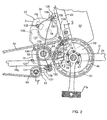
- FIGS. 1 to 14 show a first working example when the present invention is applied to a motor-assist bicycle.
- the present motor-assist bicycle includes a body frame 21 having a substantially U-shape which is open upwardly in side elevation, and the body frame 21 includes a head pipe 22 provided at a front end thereof, a main frame 23 extending rearwardly downwards from the head pipe 22, a support pipe 24 securely mounted at a rear end of the main frame 23 and extending leftwardly and rightwardly, and a seat post 25 extending upwardly from the support pipe 24.
- a front fork 26 is supported for steering operation on the head pipe 22, and a front wheel W F is supported for rotation at a lower end of the front fork 26 while a steering handle bar 27 is provided at an upper end of the front fork 26.
- a rear wheel W R serving as a driving wheel is supported for rotation between rear ends of a pair of left and right rear forks 28 L, 28 R which extend to the rear side from the support pipe 24 at the rear portion of the body frame 21, and a pair of left and right stays 29 ... are provided between an upper portion of the seat post 25 and the two rear forks 28 L , 28 R .
- a support shaft 31 having a seat 30 provided at an upper end thereof is mounted on the seat post 25 such that the vertical position of the seat 30 can be adjusted, and a battery accommodating box 32 for removably accommodating a battery not shown therein is provided at a front portion of the seat post 25 below the seat 30.
- a power unit 35 having an electric motor 34 to which power is supplied from the battery accommodated in the battery accommodating box 32 is arranged, and the power unit 35 is supported on the seat post 25 and the right-hand side rear fork 28 R .
- crank pedals 37 L , 37 R each serving as an input operation member are securely connected to the left end and the right end of a crankshaft 36 which coaxially extends through the support pipe 24 of the body frame 21, and a pair of ball bearings 39, 39 are provided between the crankshaft 36 and a pair of lid plates 38 L , 38 R through which the crankshaft 36 extends for rotation and which close up the left end and the right end of the support pipe 24, respectively.
- the crankshaft 36 is supported for rotation on the body frame 21.
- Treadling force by the crank pedals 37 L , 37 R at the opposite left and right ends of the crankshaft 36 is transmitted in synchronism with rotation of the crank pedals 37 L , 37 R to a first rotary disk 40 serving as a first rotation member, and a first one-way clutch 41 for interrupting torque transmission from the first rotary disk 40 to the right-hand side crank pedal 37 R is provided between the crank pedal 37 R and the first rotary disk 40.
- the first one-way clutch 41 includes a clutch inner race 42 securely mounted at a base end portion of the right-hand side crank pedal 37 R by a plurality of bolts 47 and coaxially surrounding the crankshaft 36, a clutch outer race 43 coaxially surrounding the clutch inner race 42, and a plurality of, for example, three, ratchet pawls 44 ... supported for pivotal motion on an outer periphery of the clutch inner race 42 and each biased in an expanding direction by an annular spring 45, and ratchet teeth 46 for engaging the ratchet pawls 44 ... are formed on an inner periphery of the clutch outer race 43 while an inner periphery of the first rotary disk 40 is securely mounted on an outer periphery of the clutch outer race 43 by soldering or the like.
- the first one-way clutch 41 having such a construction as described above, if the crank pedals 37 L , 37 R are treadled to rotate the crankshaft 36 forwardly, then the treadling force of the crank pedals 37 L , 37 R is transmitted to the first rotary disk 40. However, if the crank pedals 37 L , 37 R are treadled to rotate the crankshaft 36 reversely, then the first one-way clutch 41 slips to allow reverse rotation of the crankshaft 36 and no torque is transmitted from the first rotary disk 40 to the crank pedal 37 R side.
- a second rotary disk 48 serving as a second rotation member which is formed with a larger diameter than the first rotary disk 40 is arranged such that it coaxially surrounds the crankshaft 36, and an inner peripheral portion of the second rotary disk 48 is held for relative rotation between the clutch inner race 42 of the first one-way clutch 41 and a flange portion 50a provided on a cylindrical support member 50 while the support member 50 surrounds the crankshaft 36 for relative rotation and is coupled to the inner periphery of the clutch inner race 42, for example, by screw coupling.
- a ring-shaped holding plate 49 is disposed on the outer side of the first rotary disk 40 along the axial line of the crankshaft 36 such that the outer peripheral portion of the first rotary disk 40 is held between the holding plate 49 and the second rotary disk 48.
- guide holes 51, 51 ... which extend arcuately along an imaginary circle centered at the axis of the crankshaft 36 are provided, and cylindrical collars 52, 52 ... individually fitted in the guide holes 51, 51 ... are arranged between the second rotary disk 48 and the holding plate 49 while the second rotary disk 48 and the holding plate 49 are connected to each other by rivets 53, 53 ... which individually extend through the collars 52, 52 ....
- the second rotary disk 48 and the holding plate 49 can make relative rotation to the first rotary disk 40 within a range which they can move in the guide holes 51, 51 ... .
- a rustproof film (not shown) for preventing rust is adhered to each of opposing faces of the first rotary disk 40 and the second rotary disk 48 and holding plate 49.
- a plurality of accommodating holes 54, 54 ... extending comparatively long in a circumferential direction are provided in the first rotary disk 40 such that two such accommodating holes 54, 54 are arranged between each adjacent ones of the guide holes 51, 51 ..., and also the second rotary disk 48 and the holding plate 49 have provided therein control holes 55, 55 ..., 56, 56 ... which correspond to the accommodating holes 54, 54 ... of the first rotary disk 40, respectively.
- Coil springs 57, 57 ... serving as resilient members are accommodated in the accommodating holes 54, 54 ... and the control holes 55, 55 ..., 56, 56 ..., and when the first rotary disk 40 and the second rotary disk 48 and holding plate 49 do not make relative rotation, the opposite ends of the coil springs 57, 57 ...
- the first rotary disk 40 makes relative rotation to the second rotary disk 48 and the holding plate 49, then while one end of each of the coil springs 57, 57... remains in contact with one end of a corresponding one of the accommodating holes 54, 54 ..., the other end is pushed by the other end of a corresponding one of the control holes 55, 55 ..., 56, 56 ... so that it is spaced from the other end of the corresponding one of the accommodating holes 54, 54 ....
- the first rotary disk 40 makes relative rotation to the second rotary disk 48 and the holding plate 49 while compressing each of the coil springs 57, 57 ... .
- the second rotary disk 48 has wall portions 55a, 55a ... provided thereon which extend obliquely substantially along outer peripheries of the coil springs 57, 57 ... from the opposite side edges of the control holes 55, 55, ..., and the holding plate 49 has holding wall portions 56a, 56a ... provided thereon which extend obliquely substantially along the outer peripheries of the coil springs 57, 57 ... from the opposite side edges of the control holes 56, 56 ... .
- the first rotary disk 40 and the holding plate 49 are covered with a cover 58 mounted on an outer periphery of the first rotary disk 40, and a lip portion 59a provided on the outer periphery side of an annular resilient seal member 59 mounted on the clutch outer race 43 of the first one-way clutch 41 is resiliently held in contact with an inner face of an inner peripheral portion of the cover 58 while another lip portion 59b provided on an inner periphery side of the resilient seal member 59 is resiliently held in contact with the clutch inner race 42. Further, grease 60 is filled between the clutch inner race 42 and the clutch outer race 43 of the first one-way clutch 41 in such a manner that it is enclosed by the lip portion 59b.
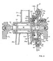
- a pedal sprocket wheel 61 is provided on an outer periphery of the second rotary disk 48 which projects outwardly sidewardly from the cover 58, and an endless chain 64 extends between and around the pedal sprocket wheel 61, a driving sprocket wheel 62 driven by the power unit 35 and a driven sprocket wheel 63 provided on an axle of the rear wheel W R while a sprocket wheel 66 provided on a tensioner 65 for applying tension to the chain 64 is meshed with the chain 64 between the driving sprocket wheel 62 and the driven sprocket wheel 63.
- the treadling force of the crank pedals 37 L , 37 R transmitted to the first rotary disk 40 through the first one-way clutch 41 is transmitted to the second rotary disk 48, that is, to the pedal sprocket wheel 61 while compressing the coil springs 57, 57 ..., and is further transmitted to the rear wheel W R through the endless chain 64 and the driven sprocket wheel 63.
- assisting power applied from the power unit 35 to the driving sprocket wheel 62 is transmitted to the rear wheel W R through the chain 64 and the driven sprocket wheel 63, but torque by the assisting power from the power unit 35 is not transmitted to the crank pedals 37 L , 37 R side due to an action of the first one-way clutch 41.
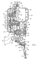
- a casing 70 of the power unit 35 includes a left casing half 71, a right casing half 72 coupled to the left casing half 71 such that it cooperates with the left casing half 71 to form a first accommodation chamber 74 therebetween, and a cover 73 coupled to the left casing half 71 such that it cooperates with the left casing half 71 to form a second accommodation chamber 75 therebetween, and a gasket 76 made of rubber is mounted on a coupling face of the cover 73 to the left casing half 71.
- the electric motor 34 having an axis of rotation parallel to the axis of rotation of the crankshaft 36 is mounted on the casing 70, and output power of the electric motor 34 is transmitted to the driving sprocket wheel 62 through a reduction gear train 77 in order to assist the treadling force by the crank pedals 37 L , 37 R .
- the reduction gear train 77 for transmitting power of the electric motor 34 to the driving sprocket wheel 62 includes a driving gear 79 securely mounted on a motor shaft 78 of the electric motor 34 in the second accommodation chamber 75, a first intermediate gear 81 securely mounted on one end of an idle shaft 80 in the second accommodation chamber 75 and held in meshing engagement with the driving gear 79, a second intermediate gear 82 provided integrally with the idle shaft 80 in the first accommodation chamber 74, a driven gear 83 held in meshing engagement with the second intermediate gear 82, a rotary shaft 84 arranged coaxially with the driven gear 83, and a second one-way clutch 85 provided between the driven gear 83 and the rotary shaft 84, and the driving sprocket wheel 62 is secured to an end portion of the rotary shaft 84 which projects from the right casing half 72.
- the idle shaft 80 has an axis parallel to the motor shaft 78 of the electric motor 34, and a ball bearing 86 is interposed between the right casing half 72 and the idle shaft 80 while another ball bearing 87 is interposed between the left casing half 71 and the idle shaft 80.
- the rotary shaft 84 has an axis parallel to the idle shaft 80, and a ball bearing 88 is interposed between the right casing half 72 and the rotary shaft 84 while another ball bearing 89 is interposed between the left casing half 71 and the rotary shaft 84.
- a fitting tubular portion 90 which projects to the side opposite to the cover 73 is provided integrally on the left casing half 71 of the casing 70, and a bottomed cylindrical motor housing 91 provided on the electric motor 34 is fastened to the left casing half 71 by a plurality of, for example, two, bolts 92, 92 in a condition wherein it is fitted with the fitting tubular portion 90.
- a positioning pin 93 implanted on the left casing half 71 is engaged with an opening of the motor housing 91 so that the motor housing 91 is positioned around the axis in the fitting tubular portion 90.
- stepped portions for holding an annular seal member 94 therebetween are formed in a corresponding relationship to each other on an outer face near to the opening end of the motor housing 91 and an inner face of the fitting tubular portion 90, and the seal member 94 is held between the motor housing 91 and the fitting tubular portion 90 by fitting and securing the motor housing 91 in the fitting tubular portion 90.
- the electric motor 34 has the motor shaft 78 having an axis parallel to the crankshaft 36, and a plurality of brushes 96 ... are held in sliding contact with a commutator 95 provided on the motor shaft 78.
- a support wall portion 100 which opposes the opening of the motor housing 91 is provided integrally on the left casing half 71 such that it closes up an inner end of the fitting tubular portion 90, and the brushes 96 ... are held between a support plate 9 ⁇ 7 made of a nonconducting material and fastened to the support wall portion 100 and holders 98 ... mounted on the support plate 97 while the brushes 96 ... are biased in a direction to slidably engage with the commutator 95 by springs 99 ... received between the holders 98 ... and the brushes 96 ... .
- the motor shaft 78 extends for rotation through the support wall portion 100 and projects to the second accommodation chamber 75 side, and a ball bearing 101 is provided between the support wall portion 100 and the motor shaft 78 such that it is force fitted in the support wall portion 100 and a snap ring 102 for preventing an inner race of the ball bearing 101 from moving to the commutator 95 side is mounted on the motor shaft 78.
- the casing 70 is supported on the seat post 25 of the body frame 21 and the right-hand side rear fork 28 R such that the electric motor 34 is arranged at an upper location on the rear side with respect to the crankshaft 36, and a hanger portion 106 provided integrally-at an upper portion of the left casing half 71 such that it swells upwardly is fastened to a bracket 105 securely mounted on the seat post 25 by a bolt 107 and a nut 108 while another hanger portion 110 provided integrally on the left, right casing halves 71, 72 such that it extends forwardly is fastened to a bracket 109 securely mounted on the right-hand side rear fork 28 R by a bolt 111 and a nut 112.
- the driving gear 79 is spline fitted at an end portion of the motor shaft 78 which projects into the second accommodation chamber 75, and a bolt 113 coaxial with the motor shaft 78 is screwed into the end portion of the motor shaft 78 such that it cooperates with the inner race of the ball bearing 101 to hold the driving gear 79 and a reluctor 114 therebetween so that movement of the driving gear 79 along the axis of the motor shaft 78 is stopped and the driving gear 79 is secured to the motor shaft 78.
- a rotational speed sensor 116 of the electromagnetic pickup coil type for cooperating with the reluctor 114 to detect the speed of rotation of the motor shaft 78 is secured to the left casing half 71 of the casing 70 such that it is arranged in an opposing relationship to the reluctor 114 in the second accommodation chamber 75 as shown in FIG. 2.
- the first intermediate gear 81 which meshes with the driving gear 79 is formed, at an outer peripheral portion, that is, a portion at which it meshes with the driving gear 79, from a synthetic resin, and a ring member 119 formed in a ring-shape from a synthetic resin and having a teethed portion 118 on an outer periphery thereof is fastened to a boss 117 made of a metal and coupled to the idle shaft 80 by means of a plurality of bolts 120 ... .
- the boss 117 is spline fitted with the idle shaft 80 such that it contacts at one end thereof with the inner race of the ball bearing 87 supported on the idle shaft 80.
- a snap ring 121 is mounted on an outer face of an end portion of the idle shaft 80, and a receiving member 122 is mounted on the idle shaft 80 such that its movement in a direction away from the boss 117 is prevented by the snap ring 121 while a disk spring 123 is provided between the other end of the boss 117 and the receiving member 122 .
- the first intermediate gear 81 is pressed toward the inner race side of the ball bearing 87 so that the first intermediate gear 81 is fixed to the idle shaft 80.
- a reinforcing plate 124 made of a metal is held in contact with the ring member 119, and the reinforcing plate 124 is fastened together with the ring member 119 by the bolts 120 ... .
- the rotary shaft 84 is supported for rotation on the casing 70 such that a lower portion of the driven gear 83 mounted on the rotary shaft 84 with the second one-way clutch 85 interposed therebetween is arranged between the left, right rear forks 28 L , 28 R , and lower portions of the left, right casing halves 71, 72 fastened to each other by a plurality of bolts 125 ... are formed such that they extend downwardly between the two rear forks 28 L , 28 R in such a manner that they cover over a lower portion of the driven gear 83.
- the center of gravity of the power unit 35 is arranged at a lower location to the utmost, which can contribute to arrangement of the center of gravity to a lower location of the motor-assist bicycle.
- An arm portion 126 is provided integrally at a lower end of the left casing half 71, and the tensioner 65 for tensioning the chain 64 is mounted on the arm portion 126.
- the tensioner 65 includes a lever 127 supported at a base end portion thereof on the arm portion 126 for rocking motion around an axis parallel to the rotary shaft 84, the sprocket wheel 66 supported for rotation at an end of the lever 127, and a spring 128 for biasing the lever 127 in a direction to tension the chain 64 meshing with the sprocket wheel 66.
- the lever 127 has a cylindrical portion 127a provided at a base end portion thereof, and a cylindrical support shaft 129 inserted in the cylindrical portion 127a is fastened to the arm portion 126 by a bolt 130 such that it has an axis parallel to the rotary shaft 84.
- the spring 128 is a torsion spring which surrounds the cylindrical portion 127a, and the opposite ends of the spring 128 are engaged with the arm portion 126 and the lever 127.
- a shaft 131 having an axis parallel to the support shaft 129 is securely mounted at an end portion of the lever 127, and the sprocket wheel 66 is mounted at an end portion of the lever 127 such that a ball bearing 132 is interposed between the sprocket wheel 66 and the shaft 131.
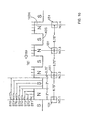
- a recessed portion 135 is provided on the outer face side of the left casing half 71 between the rotary shaft 84 and the electric motor 34, and a cover 137 which covers over the recessed portion 135 and part of the electric motor 34 is fastened to the left casing half 71 by a plurality of bolts 138 ... and a control unit 140 is accommodated in an accommodation chamber 136 formed by the cover 137 and the recessed portion 135.
- Operation of the electric motor 34 is controlled by the control unit 140, and the control unit 140 controls operation of the electric motor 34 based on a speed of rotation of the electric motor 34 detected by the rotational speed sensor 116 and an input torque from the crank pedals 37 L, 37 R .
- a guide projection 139 which guides circulation of the chain 64 such that a portion of the chain 64 wound on the driving sprocket wheel 62 and another portion of the chain 64 which extends from the driven sprocket wheel 63 to the pedal sprocket wheel 61 may be prevented from contacting with each other.
- a first magnetic ring 141 which rotates together with the first rotary disk 40 is arranged on the side opposite to the first rotary disk 40 with respect to the second rotary disk 48, and a second magnetic ring 142 which rotates together with the second rotary disk 48 is arranged at a position at which it cooperates with the first magnetic ring 141 to hold the second rotary disk 48 therebetween.
- the first and second magnetic rings 141, 142 are arranged in a juxtaposed relationship in an axial direction on one side of the axial direction of the first and second rotary disks 40, 48.
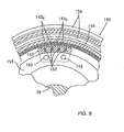
- the first magnetic ring 141 is constructed such that a plurality of N poles 143 N ... and a plurality of S poles 143 S ... arranged in a ring-shaped configuration such that each two adjacent ones of them in a circumferential direction have different polarities from each other are provided on an inner periphery of a cylindrical first housing 144 which is made of a non-magnetic material such as a synthetic resin, and, for example, 60 such N poles 143 N ... and 60 such S poles 143 S ... are provided on the inner periphery of the first housing 144 such that each of them has a central angle of, for example, 3 degrees.
- insertion holes 145 ... are provided at a plurality of, for example, four, locations in a circumerential direction of the second rotary disk 48 adjacent the first magnetic ring 141, and engaging holes 146 ... corresponding to the insertion holes 145 ... are provided on the first rotary disk 40.
- contacting leg portions 144a ... which extend through the insertion holes 145 ... and contact with the first rotary disk 40 and engaging pawl portions 144b ... which extend through the insertion holes 145 ... and resiliently engage with the engaging holes 146 ... are provided integrally on the first housing 144 of the first magnetic ring 141, and the first magnetic ring 141 is resiliently engaged with the first rotary disk 40.
- the insertion holes 145 ... are formed comparatively long along a circumferential direction of the second rotary disk 48 so that, also when the first and second rotary disks 40, 48 rotate relative to each other, the contacting leg portions 144a ... and the engaging pawl portions 144b ... may not contact with the opposite sides of the insertion holes 145 ... in the circumferential direction.
- the second magnetic ring 142 is constructed such that a plurality of N poles 147 N ... and a plurality of S poles 147 S arranged in a ring-shaped configuration such that each adjacent ones of them in a circumferential direction may have different polarities from each other are provided on an inner periphery of a cylindrical second housing 148 made of a non-magnetic material such as a synthetic resin, and the N poles 147 N ... and the S poles 147 S are provided on the inner periphery of the second housing 148 such that they have an equal angle to that of the N poles 143 N ... and the S poles 143 S ... of the first magnetic ring 141.
- Engaging holes 149 ... are provided at a plurality of locations, for example, at four locations, in a circumferential direction of the second rotary disk 48, and a plurality of, for example, four, contacting leg portions 148a ... which contact with the second rotary disk 48 and engaging pawl portions 148b ... which resiliently engage with the engaging holes 149 ... are provided integrally on the second housing 148 of the second magnetic ring 142 and the second magnetic ring 142 is resiliently engaged with the second rotary disk 48. Further, since openings 150 ... in which the engaging pawl portions 148b ... engaged with the engaging holes 149 ...
- the openings 150 ... are formed comparatively long along a circumferential direction of the first rotary disk 40 so that, also when the first and second rotary disks 40, 48 rotate relative to each other, the pawl portions 148b ... are not contacted with the opposite sides of the openings 150 ... in the circumferential direction.
- a cover portion 148c extending outwardly in a radial direction from the entire periphery at positions at which the contacting leg portions 148a are provided is provided integrally on the second housing 148 of the second magnetic ring 142, and portions corresponding to the control holes 55 ... of the second rotary disk 48 on the opposite side to the first rotary disk 40 are covered with the cover portion 148c.
- first sensors 151 ... for detecting the N poles 143 N ... and the S poles 143 S provided on the inner periphery of the first magnetic ring 141 are arranged in an equally spaced relationship from each other in the circumferential direction
- second sensors 152 ... for detecting the N poles 147 N ... and the S poles 147 S ... provided on the inner periphery of the second magnetic ring 142 are arranged in an equally spaced relationship from each other in the circumferential direction.
- the first and second sensors 151..., 152 ... are required only that they can detect a magnetic pole, and, for example, a Hall effect element or an MR element is used preferably.
- the first sensors 151 ... and the second sensors 152 ... are embedded in a base member 153 made of a synthetic resin or the like, and the base member 153 is fastened to a support ring 154 held between the lid plate 38 R screwed to the right end of the support pipe 24 of the body frame 21 and the right end of the support pipe 24 by a plurality of, for example, two, screw members 155, 155.
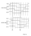
- the four first sensors 151 ... are embedded in the base member 153 in a spaced relationship from each other by 6.75 degrees while each of the N poles 143 N ... and the S poles 143 S has an angle of 3 degrees, and according to such an arrangement of the N poles 143 N ... and S poles 143 S ... and the first sensors 151 ... as just described, when the first magnetic ring 141 is angularly displaced in a direction indicated by an arrow mark in FIG. 10 with respect to the fixed first sensors 151 ..., the combination pattern of detection signals of the four first sensors 151 ... is different for different stages, ST1 to ST8 from the first stage ST13 to the eighth stage ST8 set for each 0.75 degrees.
- the four first sensors 151 ... are numbered to NO. 1 to NO. 4 in the order of the arrangement thereof, and if it is assumed that each of the first sensors 151 outputs a signal of the high level when an N pole 143 N is detected, then the first sensors 151 ... of NO.1 to NO. 4 output such signals as illustrated in FIG. 11 for each stages ST1 to ST8.
- the high level signal is represented by "1” and the low level signal is represented by "0”
- the combination of the output signals of the first sensors 151 ... is "1111" in binary number (0F in hexadecimal number); in the second stage ST2, the combination of the output signals of the first sensors 151 ...
- the combination of the output signals of the first sensors 151 ... is "1110” in binary number (0E in hexadecimal number); in the third stage ST3, the combination of the output signals of the first sensors 151 ... is “1100” in binary number (0C in hexadecimal number); in the fourth stage ST4, the combination of the output signals of the first sensors 151 ... is "1000" in binary number (08 in hexadecimal number); in the fifth stage ST5, the combination of the output signals of the first sensors 151 ... is "0000” in binary number (00 in hexadecimal number); in the sixth stage ST6, the combination of the output signals of the first sensors 151 ...
- the four second sensors 152 ... are embedded in the base member 153 such that they have a same relative positional relationship to the N poles 147 N and S poles 147 S of the second magnetic ring 142 as the relative positions between the first sensors 151 ... and the N poles 143 N and S poles 143 S of the first magnetic ring 141, and each time the second magnetic ring 142 is angularly displaced from the first stage ST13 to the eighth stage ST8 with respect to the fixed second sensors 152 ..., the combination pattern of detection signals by the four second sensors 152 ... is different similarly to that by the four first sensors 151 ... .
- the control unit 140 can discriminate the rotational phase difference between the two rotary disks 40, 48.
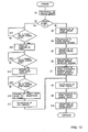
- Such detection signals of the first sensors 151 ... and the second sensors 152 ... as described above are inputted to the control unit 140, and the control unit 140 controls operation of the electric motor 34 in accordance with a control procedure illustrated in FIG. 12 in response to the detection signals of the first and second sensors 151 ..., 152 ...
- step S1 the vehicle speed is calculated, and in step S2, it is discriminated whether or not the vehicle speed is equal to or higher than a preset vehicle speed VS.
- the discrimination vehicle speed VS is set to a value close to "0", for example, to 0.5 to 1 km/h in advance in order to discriminate whether or not, upon starting of treadling of the crank pedals 37 L , 37 R , the motor-assist bicycle is in a substantially stopping state prior to starting of travelling, and if it is discriminated that the vehicle speed is lower than the preset vehicle speed VS, that is, when it is discriminated that treadling of the crank pedals 37 L , 37 R has been started, the control advances to step S3.
- step S3 the outputs of the four first sensors 151 ... are read in, and in next step S4, a detection pattern of the four first sensors 151 ... is detected. Further, in step S5, the outputs of the four second sensors 152 ... are read in, and in next step S6, a detection pattern of the four second sensors 152 ... is calculated. Furthermore, in step S7, the phase difference between the first and second magnetic rings 141, 142, that is, the rotational phase difference between the first and second rotary disks 40, 48, is calculated based on the combination of the detection patterns of the first sensors 151 ... and the second sensors 152 ....
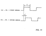
- the detection timing T1 the detection pattern of the f irst sensors 151 ... is "0E" (hexadecimal number) while the detection pattern of the second sensors 152 ... is "07" (hexadecimal number). Accordingly, while the detection pattern based on the first sensors 151 ... indicates the second stage ST2, the detection pattern based on the second sensors 152 ...
- a rotational phase difference corresponding to 1 stage or 2 stages is obtained as a digital value in step S7 based on the combinations of the detection patterns of the first sensors 151 ... and the second sensors 152 ..., and in step S8, an input torque can be obtained by multiplying the rotational phase difference by a spring constant of the coil springs 57 provided between the first and second rotary disks 40, 48.
- step S9 a motor control amount corresponding to the input torque obtained in step S8 is determined, operation of the electric motor 34 is duty controlled, and in step S9, a duty control amount of the electric motor 34 is calculated. In step S10, the control amount is outputted.
- step S2 it is discriminated whether or not the output of the first sensor 151 of NO. 1 of the four first sensors 151 has changed to the high level. If the output of the first sensor 151 has changed to the high level, then counting by a timer is started in step S12.
- step S13 it is discriminated whether the output of the second sensor 152 of NO. 1 of the four second sensors 152 ... has changed to the high level, and if the output of the second sensor 152 has changed to the high level, then the count time t of the timer is stored in step S14 when a change to the high level is detected. Further in step S15, it is discriminated whether or not the output of the first sensor 151 of NO. 1 of the four first sensors 151 ... has changed to the high level again, and when the output of the first sensor 151 changes to the high level, the count time T by the timer is stored and the timer is reset in step S16.
- the count value t represents a time difference between the outputs of the first and second sensors 151, 152, and the count value T represents a detection period of the first sensor 151 of NO. 1.
- step S17 t/T is calculated, and the phase difference between the first and second magnetic rings 141, 142, that is, the phase difference between the first and second rotary disks 40, 48, can be obtained as t/T, which is an analog value, in step S17, and thereafter, steps S8 to S10 are successively passed, thereby executing operation control of the electric motor 34 in an ordinary travelling condition of the motor-assist bicycle.
- a protective cover 158 is fastened to the support ring 154 by a plurality of screw members 159 ..., and the first and second magnetic rings 141, 142 and the base member 153 in which the f irst and second sensors 151, 152 are embedded are covered with a protective cover 158 from the side opposite to the first and second rotary disks 40, 48.
- a labyrinth structure 160 is formed between a circumferential edge portion of the protective cover 158 which is in a fixed condition and the second housing 148 of the second magnetic ring 142 which rotates around the axis of the crankshaft 36. Accordingly, pollution to the first and second sensors 151 ..., 152 ... and the two magnetic rings 141, 142 by water, mud or the like is prevented to the utmost.
- a rotational phase difference is produced between the first rotary disk 40 and the second rotary disk 48 in accordance with the treadling force by the crank pedals 37 L , 37 R then while compressing the coil springs 57 ..., and the control unit 140 calculates an input torque in accordance with the detection signals of the plurality of first sensors 151 ... which detect the N poles 143 N and S poles 143 S of the first magnetic ring 141 which rotates together with the first rotary disk 40 and the detection signals of the plurality of second sensors 152 ... which detect the N poles 147 N and S poles 147 S of the second magnetic ring 142 which rotates together with the second rotary disk 48. Then, as the control unit 140 controls the electric motor 34 so that assisting power corresponding to the input torque may be exhibited by the electric motor 34, the rotational assisting power of the driving sprocket wheel 62 is controlled and the load to the driver can be reduced.
- the first rotary disk 40 exhibits a rotational phase difference from the second rotary disk 48. Accordingly, since also the first magnetic ring 141 exhibits a rotational phase difference from the second magnetic ring 142, the combination pattern of the detection signals of the first sensors 151 ... and the second sensors 152 ...
- an input torque can be detected immediately to apply assisting power by the electric motor 34 to the rear wheel W R .
- an input torque is calculated based on a rotational phase difference obtained as a digital value
- an input torque can be calculated linearly based on a rotational phase difference obtained as an analog value, and assisting power corresponding linearly to the input torque can be obtained such that the assisting power corresponding to the linear input torque may be exhibited by the electric motor 34.
- the input torque can be detected with certainty and the assisting power by the electric motor 34 can be applied to the rear wheel W R .
- first rotary disk 40 is connected to the right-hand side crank pedal 37 R through the first one-way clutch 41 and the second rotary disk 48 between which and the first rotary disk 40 the coil springs 57 ... are provided is disposed for rotation around the same axis at a position adjacent the first rotary disk 40 while the first and second magnetic rings 141, 142 are arranged on one side of the first and second rotary disks 40, 48 in the axial direction, a space in which the first and second sensors 151, 152 are to be arranged is assured on one side of the first and second rotary disks 40, 48, and not only it becomes unnecessary to assure a surplus space in which both of the sensors 151 ..., 152 ... are to be arranged, but also the mounting operation can be facilitated by mounting the first and second magnetic rings 141, 142 and the first and second sensors 151 ..., 152 ... collectively on one side of the first and second rotary disks 40, 48.
- first and second magnetic rings 141, 142 are resiliently engaged with the first and second rotary disks 40, 48, respectively, and maintenance and mounting operations of the first and second magnetic rings 141, 142 are easy.
- both of the sensors 151 ..., 152 ... can be arranged inwardly of the cylindrical first and second magnetic rings 141, 142 to achieve further reduction in space, and further, both of the sensors 151 ..., 152 ... can be covered with the first and second housings 144, 148 to protect them.
- FIG. 15 shows a second working example of the present invention, and a base member 153 1 in which the plurality of first sensors 151 ... for detecting the N poles 143 N and S poles 143 S of the first magnetic ring 141 are built and another base member 153 2 in which the plurality of second sensors 152 ... for detecting the N poles 147 N and S poles 147 S of the second magnetic ring 142 are built may be arranged fixedly at positions spaced by 180 degrees in a circumferential direction of the crankshaft 36.
- the present invention can be applied not only to a motor-assist vehicle, but also to a motor-assist wheelchair.
- the invention makes it possible, in a motor-assist vehicle wherein assisting power corresponding to an input torque can be applied from an electric motor to a driving wheel, to detect the input torque in order to apply assisting power rapidly to the driving wheel upon starting of an operation input from a stopping condition of the vehicle.
Description
- This invention relates to an input torque detection apparatus for a motor-assist vehicle, which includes an input operation member manually operated for driving a rear wheel to rotate and an electric motor capable of providing assisting power corresponding to an input torque provided to the input operation member to the driving wheel, for detecting an input torque applied to the input operation member.
- DE-U-29608085 discloses an input torque detection apparatus according to the preamble of
claim 1. - Conventionally, an input torque detection apparatus for detecting an input torque of a motor-assist bicycle is known already by the official gazette of, for example, Japanese Patent Laid-Open Application No. Heisei 8313376 and so forth.
- However, the conventional apparatus described above is constructed such that rotation of a crank pedal is detected by a first rotation sensor while rotation of a pedal sprocket wheel is detected by a second rotation sensor, and a phase difference based on a time difference between rotation pulses which are detection signals of the two rotation sensors is recognized as an input torque. Consequently, unless pulse signals are outputted from the two rotation sensors, the time difference cannot be detected, and accordingly, in a condition of the vehicle speed = 0 wherein the pedal sprocket wheel is not rotating, it is impossible to detect an input torque and power assistance by an electric motor cannot be performed upon starting of treadling of the crank pedal from a stopping condition of the vehicle.
- The present invention has been made in view of such a situation as described above, and it is an object of the present invention to provide an input torque detection apparatus for a motor-assist vehicle which allows detection of an input torque in order to apply assisting power to a driving wheel rapidly upon starting of operation inputting from a stopping condition of the vehicle.
- In order to attain the object described above, according to the invention as set forth in
claim 1, there is provided an input torque detection apparatus for a motor-assist vehicle, which vehicle includes an input operation member manually operated for driving a rear wheel to rotate and an electric motor capable of providing assisting power corresponding to an input torque provided to the input operation member to the driving wheel wherein the apparatus comprises a first rotary member adapted to rotate in synchronism with the rotation of the input operation member, a second rotary member adapted to rotate in synchronism with the rotation of the driving wheel while allowing a phase difference in the direction of rotation from the first rotary member to be produced, a first magnetic ring which has a plurality of N poles and S poles arranged in a ring-like configuration and having different polarities adjacent each other in a circumferential direction and rotates together with the first rotary member, a second magnetic ring which has a plurality of N poles and S poles arranged in a ring-like configuration with an equal angle to that of the N poles and S poles of the first magnetic ring and rotates together with the second rotary member, a plurality of first sensors arranged at fixed positions in an opposing relationship to the first magnetic ring for detecting the N poles and S poles of the first magnetic ring, a plurality of second sensors arranged at fixed positions in an opposing relationship to the second magnetic ring for detecting the N poles and S poles of the second magnetic ring, and a control unit for discriminating a rotational phase difference between the first and second rotary members based on a combination pattern of detection signals of the first and second sensors and recognizing the rotational phase difference as an information representing said input torque applied to the input operation member to control operation of the electric motor. - With such a construction as described above, since, even in a condition wherein the driving wheel is not rotating in an initial stage of operation of the input operation member, the first rotary member provides a rotational phase difference from the second rotary member and also the first magnetic ring provides a rotational phase difference from the second magnetic ring, the combination pattern of the detection signals of the plurality of first sensors and the plurality of second sensors varies comparing with that prior to the operation of the input operation member, and in an initial stage of starting of the inputting operation in a stopping condition of the vehicle, the input torque can be detected and assisting power by the electric motor can be provided to the driving wheel immediately.
- Meanwhile, according to the invention as set forth in
claim 2, the input torque detection apparatus for a motor-assist vehicle is constructed, in addition to the construction of the invention as set forth inclaim 1 described above, such that the first rotary member is connectable the input operation member through a one-way clutch which interrupts torque transmission from the first rotary member side to the input operation member side, and the second rotary member between which and the f irst rotary member a coil spring is interposed is arranged at a position adjacent the first rotary member in such a manner as to allow rotation thereof around a same axis as that of the first rotary member while the first and second magnetic rings juxtaposed in the axial direction of the first and second rotary members are arranged on one side in the axial direction of the first and second rotary members . Consequently, not only a space in which the first and second sensors should be arranged is assured on one side of the first and second rotary members, thereby eliminating the necessity to assure a surplus space for arrangement of the two sensors, but also the first and second magnetic rings and the first and second sensors can be mounted collectively on one side of the two rotary members, thereby facilitating the mounting operation for them. The space for arrangement of the two sensors is reduced to the utmost. - According to the invention as set forth in
claim 3, the input torque detection apparatus for a motor-assist vehicle is constructed, in addition to the construction of the invention as set forth inclaim 2 described above, such that the first and second magnetic rings are resiliently engaged with the first and second rotary members, respectively. Consequently, maintenance and mounting operations of the first and second magnetic rings are facilitated. - According to the invention as set forth in claim 4, the input torque detection apparatus for a motor-assist vehicle is constructed, in addition to the construction of the invention as set forth in
claim - According to the invention as set forth in
claim 5, the input torque detection apparatus for a motor-assist vehicle is constructed, in addition to the construction of the invention as set forth inclaim 2 described above, such that the first and second magnetic rings and first and second sensors are covered with a protective cover from the opposite side to the first and second rotary members. Consequently, pollution to the two sensors and the two magnetic rings by water, mud or the like can be prevented. - In the following, an embodiment of the present invention is described in connection with working examples of the present invention shown in the accompanying drawings.
- FIG. 1 is a side elevational view of a motor-assist bicycle of a first working example.
- FIG. 2 is an enlarged view of essential part of FIG. 1.
- FIG. 3 is a sectional view taken along line 3-3 of FIG. 2.
- FIG. 4 is an enlarged view of essential part of FIG. 3.
- FIG. 5 is a sectional view taken along line 5-5 of FIG.4.
- FIG. 6 is a sectional view taken along line 6-6 of FIG. 4.
- FIG. 7 is an enlarged sectional view taken along line 7-7 of FIG. 2.
- FIG. 8 is a sectional view taken along line 8-8 of FIG. 4.
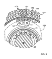
- FIG. 9 is a sectional view taken along line 9-9 of FIG.4.
- FIG. 10 is a view showing a relative arrangement of first sensors and magnetic poles of a first magnetic ring.
- FIG. 11 is a view for explaining a detection pattern of the first sensors with respect to a variation of the relative position with the first magnetic ring in a circumferential direction.
- FIG. 12 is a flow chart illustrating a control procedure of an electric motor of a control unit.
- FIG. 13 is a view for explaining detection patterns of the first and second sensors with respect to relative rotation of the first and second magnetic rings.
- FIG. 14 is a view for explaining phase difference detection in an ordinary travelling condition.
- FIG. 15 is a sectional view of a second working example corresponding to FIGS. 8 and 9.
-
- FIGS. 1 to 14 show a first working example when the present invention is applied to a motor-assist bicycle.
- Referring first to FIGS. 1 to 3, the present motor-assist bicycle includes a
body frame 21 having a substantially U-shape which is open upwardly in side elevation, and thebody frame 21 includes ahead pipe 22 provided at a front end thereof, amain frame 23 extending rearwardly downwards from thehead pipe 22, asupport pipe 24 securely mounted at a rear end of themain frame 23 and extending leftwardly and rightwardly, and aseat post 25 extending upwardly from thesupport pipe 24. - A
front fork 26 is supported for steering operation on thehead pipe 22, and a front wheel WF is supported for rotation at a lower end of thefront fork 26 while asteering handle bar 27 is provided at an upper end of thefront fork 26. Meanwhile, a rear wheel WR serving as a driving wheel is supported for rotation between rear ends of a pair of left and right rear forks 28L, 28R which extend to the rear side from thesupport pipe 24 at the rear portion of thebody frame 21, and a pair of left andright stays 29 ... are provided between an upper portion of theseat post 25 and the two rear forks 28L, 28R. - A
support shaft 31 having aseat 30 provided at an upper end thereof is mounted on theseat post 25 such that the vertical position of theseat 30 can be adjusted, and abattery accommodating box 32 for removably accommodating a battery not shown therein is provided at a front portion of theseat post 25 below theseat 30. - On the rear side of the
battery accommodating box 32, apower unit 35 having anelectric motor 34 to which power is supplied from the battery accommodated in thebattery accommodating box 32 is arranged, and thepower unit 35 is supported on theseat post 25 and the right-hand side rear fork 28R. - A pair of crank pedals 37L, 37R each serving as an input operation member are securely connected to the left end and the right end of a
crankshaft 36 which coaxially extends through thesupport pipe 24 of thebody frame 21, and a pair ofball bearings crankshaft 36 and a pair of lid plates 38L, 38R through which thecrankshaft 36 extends for rotation and which close up the left end and the right end of thesupport pipe 24, respectively. In other words, thecrankshaft 36 is supported for rotation on thebody frame 21. - Treadling force by the crank pedals 37L, 37R at the opposite left and right ends of the
crankshaft 36 is transmitted in synchronism with rotation of the crank pedals 37L, 37R to a firstrotary disk 40 serving as a first rotation member, and a first one-way clutch 41 for interrupting torque transmission from the firstrotary disk 40 to the right-hand side crank pedal 37R is provided between the crank pedal 37R and the firstrotary disk 40. - Referring also to FIGS. 4 to 6, the first one-
way clutch 41 includes a clutchinner race 42 securely mounted at a base end portion of the right-hand side crank pedal 37R by a plurality ofbolts 47 and coaxially surrounding thecrankshaft 36, a clutchouter race 43 coaxially surrounding the clutchinner race 42, and a plurality of, for example, three,ratchet pawls 44 ... supported for pivotal motion on an outer periphery of the clutchinner race 42 and each biased in an expanding direction by anannular spring 45, andratchet teeth 46 for engaging theratchet pawls 44 ... are formed on an inner periphery of the clutchouter race 43 while an inner periphery of the firstrotary disk 40 is securely mounted on an outer periphery of the clutchouter race 43 by soldering or the like. - With the first one-
way clutch 41 having such a construction as described above, if the crank pedals 37L, 37R are treadled to rotate thecrankshaft 36 forwardly, then the treadling force of the crank pedals 37L, 37R is transmitted to the firstrotary disk 40. However, if the crank pedals 37L, 37R are treadled to rotate thecrankshaft 36 reversely, then the first one-way clutch 41 slips to allow reverse rotation of thecrankshaft 36 and no torque is transmitted from the firstrotary disk 40 to the crank pedal 37R side. - At a position on the inner side adjacent the first
rotary disk 40 along the axis of thecrankshaft 36, a secondrotary disk 48 serving as a second rotation member which is formed with a larger diameter than the firstrotary disk 40 is arranged such that it coaxially surrounds thecrankshaft 36, and an inner peripheral portion of the secondrotary disk 48 is held for relative rotation between the clutchinner race 42 of the first one-way clutch 41 and a flange portion 50a provided on acylindrical support member 50 while thesupport member 50 surrounds thecrankshaft 36 for relative rotation and is coupled to the inner periphery of the clutchinner race 42, for example, by screw coupling. Meanwhile, a ring-shaped holding plate 49 is disposed on the outer side of the firstrotary disk 40 along the axial line of thecrankshaft 36 such that the outer peripheral portion of the firstrotary disk 40 is held between theholding plate 49 and the secondrotary disk 48. - At a plurality of locations, for example, at four locations, spaced equally from each other along a circumferential direction at a portion near to the outer periphery of the first
rotary disk 40,guide holes crankshaft 36 are provided, andcylindrical collars guide holes rotary disk 48 and theholding plate 49 while the secondrotary disk 48 and theholding plate 49 are connected to each other byrivets collars rotary disk 48 and theholding plate 49 can make relative rotation to the firstrotary disk 40 within a range which they can move in theguide holes rotary disk 40 and the secondrotary disk 48 and holdingplate 49. - A plurality of
accommodating holes rotary disk 40 such that two suchaccommodating holes guide holes rotary disk 48 and theholding plate 49 have providedtherein control holes accommodating holes rotary disk 40, respectively.Coil springs holes control holes rotary disk 40 and the secondrotary disk 48 and holdingplate 49 do not make relative rotation, the opposite ends of thecoil springs holes control holes rotary disk 40 makes relative rotation to the secondrotary disk 48 and theholding plate 49, then while one end of each of thecoil springs accommodating holes control holes accommodating holes rotary disk 40 makes relative rotation to the secondrotary disk 48 and theholding plate 49 while compressing each of thecoil springs - In order to keep the accommodated condition of the
coil springs holes control holes rotary disk 48 haswall portions coil springs control holes holding plate 49 has holdingwall portions coil springs control holes - The first
rotary disk 40 and theholding plate 49 are covered with acover 58 mounted on an outer periphery of the firstrotary disk 40, and alip portion 59a provided on the outer periphery side of an annularresilient seal member 59 mounted on the clutchouter race 43 of the first one-way clutch 41 is resiliently held in contact with an inner face of an inner peripheral portion of thecover 58 while anotherlip portion 59b provided on an inner periphery side of theresilient seal member 59 is resiliently held in contact with the clutchinner race 42. Further, grease 60 is filled between the clutchinner race 42 and the clutchouter race 43 of the first one-way clutch 41 in such a manner that it is enclosed by thelip portion 59b. - A
pedal sprocket wheel 61 is provided on an outer periphery of the secondrotary disk 48 which projects outwardly sidewardly from thecover 58, and anendless chain 64 extends between and around thepedal sprocket wheel 61, a drivingsprocket wheel 62 driven by thepower unit 35 and a drivensprocket wheel 63 provided on an axle of the rear wheel WR while asprocket wheel 66 provided on atensioner 65 for applying tension to thechain 64 is meshed with thechain 64 between the drivingsprocket wheel 62 and the drivensprocket wheel 63. - Accordingly, the treadling force of the crank pedals 37L, 37R transmitted to the first
rotary disk 40 through the first one-way clutch 41 is transmitted to the secondrotary disk 48, that is, to thepedal sprocket wheel 61 while compressing thecoil springs endless chain 64 and the drivensprocket wheel 63. Meanwhile, assisting power applied from thepower unit 35 to the drivingsprocket wheel 62 is transmitted to the rear wheel WR through thechain 64 and the drivensprocket wheel 63, but torque by the assisting power from thepower unit 35 is not transmitted to the crank pedals 37L, 37R side due to an action of the first one-way clutch 41. - Referring to FIG. 7, a
casing 70 of thepower unit 35 includes aleft casing half 71, aright casing half 72 coupled to theleft casing half 71 such that it cooperates with theleft casing half 71 to form afirst accommodation chamber 74 therebetween, and a cover 73 coupled to theleft casing half 71 such that it cooperates with theleft casing half 71 to form asecond accommodation chamber 75 therebetween, and agasket 76 made of rubber is mounted on a coupling face of the cover 73 to theleft casing half 71. - The
electric motor 34 having an axis of rotation parallel to the axis of rotation of thecrankshaft 36 is mounted on thecasing 70, and output power of theelectric motor 34 is transmitted to the drivingsprocket wheel 62 through areduction gear train 77 in order to assist the treadling force by the crank pedals 37L, 37R. - The
reduction gear train 77 for transmitting power of theelectric motor 34 to the drivingsprocket wheel 62 includes adriving gear 79 securely mounted on amotor shaft 78 of theelectric motor 34 in thesecond accommodation chamber 75, a firstintermediate gear 81 securely mounted on one end of anidle shaft 80 in thesecond accommodation chamber 75 and held in meshing engagement with thedriving gear 79, a secondintermediate gear 82 provided integrally with theidle shaft 80 in thefirst accommodation chamber 74, a drivengear 83 held in meshing engagement with the secondintermediate gear 82, arotary shaft 84 arranged coaxially with the drivengear 83, and a second one-way clutch 85 provided between the drivengear 83 and therotary shaft 84, and the drivingsprocket wheel 62 is secured to an end portion of therotary shaft 84 which projects from theright casing half 72. - The
idle shaft 80 has an axis parallel to themotor shaft 78 of theelectric motor 34, and a ball bearing 86 is interposed between theright casing half 72 and theidle shaft 80 while another ball bearing 87 is interposed between theleft casing half 71 and theidle shaft 80. Therotary shaft 84 has an axis parallel to theidle shaft 80, and aball bearing 88 is interposed between theright casing half 72 and therotary shaft 84 while anotherball bearing 89 is interposed between theleft casing half 71 and therotary shaft 84. - In the
reduction gear train 77 having such a construction as described above, torque produced upon operation of theelectric motor 34 is transmitted in a reduced speed to the drivingsprocket wheel 62, but when the operation of theelectric motor 34 stops, idle rotation of therotary shaft 84 is allowed because of an action of the second one-way clutch 85, and rotation of the drivingsprocket wheel 62 by the treadling force of the crank pedals 37L, 37R is not disturbed. - A
fitting tubular portion 90 which projects to the side opposite to the cover 73 is provided integrally on theleft casing half 71 of thecasing 70, and a bottomedcylindrical motor housing 91 provided on theelectric motor 34 is fastened to theleft casing half 71 by a plurality of, for example, two,bolts fitting tubular portion 90. Besides, apositioning pin 93 implanted on theleft casing half 71 is engaged with an opening of themotor housing 91 so that themotor housing 91 is positioned around the axis in thefitting tubular portion 90. Further, stepped portions for holding anannular seal member 94 therebetween are formed in a corresponding relationship to each other on an outer face near to the opening end of themotor housing 91 and an inner face of thefitting tubular portion 90, and theseal member 94 is held between themotor housing 91 and thefitting tubular portion 90 by fitting and securing themotor housing 91 in thefitting tubular portion 90. - The
electric motor 34 has themotor shaft 78 having an axis parallel to thecrankshaft 36, and a plurality ofbrushes 96 ... are held in sliding contact with acommutator 95 provided on themotor shaft 78. Further, asupport wall portion 100 which opposes the opening of themotor housing 91 is provided integrally on theleft casing half 71 such that it closes up an inner end of thefitting tubular portion 90, and thebrushes 96 ... are held between asupport plate 9·7 made of a nonconducting material and fastened to thesupport wall portion 100 andholders 98 ... mounted on thesupport plate 97 while thebrushes 96 ... are biased in a direction to slidably engage with thecommutator 95 bysprings 99 ... received between theholders 98 ... and thebrushes 96 ... . - The
motor shaft 78 extends for rotation through thesupport wall portion 100 and projects to thesecond accommodation chamber 75 side, and aball bearing 101 is provided between thesupport wall portion 100 and themotor shaft 78 such that it is force fitted in thesupport wall portion 100 and asnap ring 102 for preventing an inner race of theball bearing 101 from moving to thecommutator 95 side is mounted on themotor shaft 78. - By the way, the
casing 70 is supported on theseat post 25 of thebody frame 21 and the right-hand side rear fork 28R such that theelectric motor 34 is arranged at an upper location on the rear side with respect to thecrankshaft 36, and ahanger portion 106 provided integrally-at an upper portion of theleft casing half 71 such that it swells upwardly is fastened to abracket 105 securely mounted on theseat post 25 by abolt 107 and anut 108 while anotherhanger portion 110 provided integrally on the left, right casing halves 71, 72 such that it extends forwardly is fastened to a bracket 109 securely mounted on the right-hand side rear fork 28R by abolt 111 and anut 112. - The
driving gear 79 is spline fitted at an end portion of themotor shaft 78 which projects into thesecond accommodation chamber 75, and abolt 113 coaxial with themotor shaft 78 is screwed into the end portion of themotor shaft 78 such that it cooperates with the inner race of theball bearing 101 to hold thedriving gear 79 and areluctor 114 therebetween so that movement of thedriving gear 79 along the axis of themotor shaft 78 is stopped and thedriving gear 79 is secured to themotor shaft 78. - A
rotational speed sensor 116 of the electromagnetic pickup coil type for cooperating with thereluctor 114 to detect the speed of rotation of themotor shaft 78 is secured to theleft casing half 71 of thecasing 70 such that it is arranged in an opposing relationship to thereluctor 114 in thesecond accommodation chamber 75 as shown in FIG. 2. - The first
intermediate gear 81 which meshes with thedriving gear 79 is formed, at an outer peripheral portion, that is, a portion at which it meshes with thedriving gear 79, from a synthetic resin, and aring member 119 formed in a ring-shape from a synthetic resin and having a teethedportion 118 on an outer periphery thereof is fastened to aboss 117 made of a metal and coupled to theidle shaft 80 by means of a plurality ofbolts 120 ... . - The
boss 117 is spline fitted with theidle shaft 80 such that it contacts at one end thereof with the inner race of theball bearing 87 supported on theidle shaft 80. Meanwhile, asnap ring 121 is mounted on an outer face of an end portion of theidle shaft 80, and a receivingmember 122 is mounted on theidle shaft 80 such that its movement in a direction away from theboss 117 is prevented by thesnap ring 121 while adisk spring 123 is provided between the other end of theboss 117 and the receivingmember 122 . By a spring force exerted by thedisk spring 123, the firstintermediate gear 81 is pressed toward the inner race side of theball bearing 87 so that the firstintermediate gear 81 is fixed to theidle shaft 80. Meanwhile, a reinforcingplate 124 made of a metal is held in contact with thering member 119, and the reinforcingplate 124 is fastened together with thering member 119 by thebolts 120 ... . - The
rotary shaft 84 is supported for rotation on thecasing 70 such that a lower portion of the drivengear 83 mounted on therotary shaft 84 with the second one-way clutch 85 interposed therebetween is arranged between the left, right rear forks 28L, 28R, and lower portions of the left, right casing halves 71, 72 fastened to each other by a plurality ofbolts 125 ... are formed such that they extend downwardly between the two rear forks 28L, 28R in such a manner that they cover over a lower portion of the drivengear 83. Since the lower portions of the left, right casing halves 71, 72, that is, the lower portions of thecasing 70, are arranged lower than the two rear forks 28L, 28R in this manner, the center of gravity of thepower unit 35 is arranged at a lower location to the utmost, which can contribute to arrangement of the center of gravity to a lower location of the motor-assist bicycle. - An
arm portion 126 is provided integrally at a lower end of theleft casing half 71, and thetensioner 65 for tensioning thechain 64 is mounted on thearm portion 126. Thetensioner 65 includes alever 127 supported at a base end portion thereof on thearm portion 126 for rocking motion around an axis parallel to therotary shaft 84, thesprocket wheel 66 supported for rotation at an end of thelever 127, and aspring 128 for biasing thelever 127 in a direction to tension thechain 64 meshing with thesprocket wheel 66. - The
lever 127 has acylindrical portion 127a provided at a base end portion thereof, and acylindrical support shaft 129 inserted in thecylindrical portion 127a is fastened to thearm portion 126 by a bolt 130 such that it has an axis parallel to therotary shaft 84. Thespring 128 is a torsion spring which surrounds thecylindrical portion 127a, and the opposite ends of thespring 128 are engaged with thearm portion 126 and thelever 127. - A
shaft 131 having an axis parallel to thesupport shaft 129 is securely mounted at an end portion of thelever 127, and thesprocket wheel 66 is mounted at an end portion of thelever 127 such that aball bearing 132 is interposed between thesprocket wheel 66 and theshaft 131. - A recessed
portion 135 is provided on the outer face side of theleft casing half 71 between therotary shaft 84 and theelectric motor 34, and acover 137 which covers over the recessedportion 135 and part of theelectric motor 34 is fastened to theleft casing half 71 by a plurality ofbolts 138 ... and acontrol unit 140 is accommodated in anaccommodation chamber 136 formed by thecover 137 and the recessedportion 135. - Operation of the
electric motor 34 is controlled by thecontrol unit 140, and thecontrol unit 140 controls operation of theelectric motor 34 based on a speed of rotation of theelectric motor 34 detected by therotational speed sensor 116 and an input torque from the crank pedals 37L, 37R. - Provided integrally in a projecting condition on an outer face of the
cover 137 is aguide projection 139 which guides circulation of thechain 64 such that a portion of thechain 64 wound on the drivingsprocket wheel 62 and another portion of thechain 64 which extends from the drivensprocket wheel 63 to thepedal sprocket wheel 61 may be prevented from contacting with each other. - Referring back to FIG. 4, a first
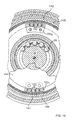
magnetic ring 141 which rotates together with thefirst rotary disk 40 is arranged on the side opposite to thefirst rotary disk 40 with respect to thesecond rotary disk 48, and a secondmagnetic ring 142 which rotates together with thesecond rotary disk 48 is arranged at a position at which it cooperates with the firstmagnetic ring 141 to hold thesecond rotary disk 48 therebetween. In particular, the first and secondmagnetic rings rotary disks - Referring also to FIG. 8, the first
magnetic ring 141 is constructed such that a plurality of N poles 143N ... and a plurality of S poles 143S ... arranged in a ring-shaped configuration such that each two adjacent ones of them in a circumferential direction have different polarities from each other are provided on an inner periphery of a cylindricalfirst housing 144 which is made of a non-magnetic material such as a synthetic resin, and, for example, 60 such N poles 143N ... and 60 such S poles 143S ... are provided on the inner periphery of thefirst housing 144 such that each of them has a central angle of, for example, 3 degrees. - By the way, insertion holes 145 ... are provided at a plurality of, for example, four, locations in a circumerential direction of the
second rotary disk 48 adjacent the firstmagnetic ring 141, and engagingholes 146 ... corresponding to the insertion holes 145 ... are provided on thefirst rotary disk 40. Meanwhile, contactingleg portions 144a ... which extend through the insertion holes 145 ... and contact with thefirst rotary disk 40 and engagingpawl portions 144b ... which extend through the insertion holes 145 ... and resiliently engage with the engagingholes 146 ... are provided integrally on thefirst housing 144 of the firstmagnetic ring 141, and the firstmagnetic ring 141 is resiliently engaged with thefirst rotary disk 40. Thus, since the first and secondrotary disks second rotary disk 48 so that, also when the first and secondrotary disks leg portions 144a ... and the engagingpawl portions 144b ... may not contact with the opposite sides of the insertion holes 145 ... in the circumferential direction. - Referring also to FIG. 9, the second
magnetic ring 142 is constructed such that a plurality of N poles 147N ... and a plurality of S poles 147S arranged in a ring-shaped configuration such that each adjacent ones of them in a circumferential direction may have different polarities from each other are provided on an inner periphery of a cylindricalsecond housing 148 made of a non-magnetic material such as a synthetic resin, and the N poles 147N ... and the S poles 147S are provided on the inner periphery of thesecond housing 148 such that they have an equal angle to that of the N poles 143N ... and the S poles 143S ... of the firstmagnetic ring 141. - Engaging
holes 149 ... are provided at a plurality of locations, for example, at four locations, in a circumferential direction of thesecond rotary disk 48, and a plurality of, for example, four, contactingleg portions 148a ... which contact with thesecond rotary disk 48 and engagingpawl portions 148b ... which resiliently engage with the engagingholes 149 ... are provided integrally on thesecond housing 148 of the secondmagnetic ring 142 and the secondmagnetic ring 142 is resiliently engaged with thesecond rotary disk 48. Further, sinceopenings 150 ... in which the engagingpawl portions 148b ... engaged with the engagingholes 149 ... are arranged are provided on thefirst rotary disk 40 and the first and secondrotary disks openings 150 ... are formed comparatively long along a circumferential direction of thefirst rotary disk 40 so that, also when the first and secondrotary disks pawl portions 148b ... are not contacted with the opposite sides of theopenings 150 ... in the circumferential direction. - Further, a
cover portion 148c extending outwardly in a radial direction from the entire periphery at positions at which the contactingleg portions 148a are provided is provided integrally on thesecond housing 148 of the secondmagnetic ring 142, and portions corresponding to the control holes 55 ... of thesecond rotary disk 48 on the opposite side to thefirst rotary disk 40 are covered with thecover portion 148c. - Inwardly of the first
magnetic ring 141, for example, fourfirst sensors 151 ... for detecting the N poles 143N ... and the S poles 143S provided on the inner periphery of the firstmagnetic ring 141 are arranged in an equally spaced relationship from each other in the circumferential direction, and inwardly of the secondmagnetic ring 142, for example, foursecond sensors 152 ... for detecting the N poles 147N ... and the S poles 147S ... provided on the inner periphery of the secondmagnetic ring 142 are arranged in an equally spaced relationship from each other in the circumferential direction. The first andsecond sensors 151..., 152 ... are required only that they can detect a magnetic pole, and, for example, a Hall effect element or an MR element is used preferably. - The
first sensors 151 ... and thesecond sensors 152 ... are embedded in abase member 153 made of a synthetic resin or the like, and thebase member 153 is fastened to asupport ring 154 held between the lid plate 38R screwed to the right end of thesupport pipe 24 of thebody frame 21 and the right end of thesupport pipe 24 by a plurality of, for example, two,screw members - Referring to FIG. 10, the four
first sensors 151 ... are embedded in thebase member 153 in a spaced relationship from each other by 6.75 degrees while each of the N poles 143N ... and the S poles 143S has an angle of 3 degrees, and according to such an arrangement of the N poles 143N ... and S poles 143S ... and thefirst sensors 151 ... as just described, when the firstmagnetic ring 141 is angularly displaced in a direction indicated by an arrow mark in FIG. 10 with respect to the fixedfirst sensors 151 ..., the combination pattern of detection signals of the fourfirst sensors 151 ... is different for different stages, ST1 to ST8 from the first stage ST13 to the eighth stage ST8 set for each 0.75 degrees. - Here, the four
first sensors 151 ... are numbered to NO. 1 to NO. 4 in the order of the arrangement thereof, and if it is assumed that each of thefirst sensors 151 outputs a signal of the high level when an N pole 143N is detected, then thefirst sensors 151 ... of NO.1 to NO. 4 output such signals as illustrated in FIG. 11 for each stages ST1 to ST8. In other words, when the high level signal is represented by "1" and the low level signal is represented by "0", in the first stage ST1, the combination of the output signals of the first sensors 151 ... is "1111" in binary number (0F in hexadecimal number); in the second stage ST2, the combination of the output signals of the first sensors 151 ... is "1110" in binary number (0E in hexadecimal number); in the third stage ST3, the combination of the output signals of the first sensors 151 ... is "1100" in binary number (0C in hexadecimal number); in the fourth stage ST4, the combination of the output signals of the first sensors 151 ... is "1000" in binary number (08 in hexadecimal number); in the fifth stage ST5, the combination of the output signals of the first sensors 151 ... is "0000" in binary number (00 in hexadecimal number); in the sixth stage ST6, the combination of the output signals of the first sensors 151 ... is "0001" in binary number (01 in hexadecimal number); in the seventh stage ST7, the combination of the output signals of the first sensors 151 ... is "0011" in binary number ( 03 in hexadecimal number); and in the eighth stage ST8, the combination of the output signals of the first sensors 151 ... is "0111" in binary number (07 in hexadecimal number). - The four
second sensors 152 ... are embedded in thebase member 153 such that they have a same relative positional relationship to the N poles 147N and S poles 147S of the secondmagnetic ring 142 as the relative positions between thefirst sensors 151 ... and the N poles 143N and S poles 143S of the firstmagnetic ring 141, and each time the secondmagnetic ring 142 is angularly displaced from the first stage ST13 to the eighth stage ST8 with respect to the fixedsecond sensors 152 ..., the combination pattern of detection signals by the foursecond sensors 152 ... is different similarly to that by the fourfirst sensors 151 ... . - Accordingly, if the maximum value of the rotational phase difference between the first and second
rotary disks second sensors 151 ..., 152 ... varies in accordance with the rotational phase difference which is produced as an input torque is applied to the crank pedals 37L, 37R, and thecontrol unit 140 can discriminate the rotational phase difference between the tworotary disks - Such detection signals of the
first sensors 151 ... and thesecond sensors 152 ... as described above are inputted to thecontrol unit 140, and thecontrol unit 140 controls operation of theelectric motor 34 in accordance with a control procedure illustrated in FIG. 12 in response to the detection signals of the first andsecond sensors 151 ..., 152 .... - Referring to FIG . 12 , in step S1, the vehicle speed is calculated, and in step S2, it is discriminated whether or not the vehicle speed is equal to or higher than a preset vehicle speed VS. The discrimination vehicle speed VS is set to a value close to "0", for example, to 0.5 to 1 km/h in advance in order to discriminate whether or not, upon starting of treadling of the crank pedals 37L, 37R, the motor-assist bicycle is in a substantially stopping state prior to starting of travelling, and if it is discriminated that the vehicle speed is lower than the preset vehicle speed VS, that is, when it is discriminated that treadling of the crank pedals 37L, 37R has been started, the control advances to step S3.
- In step S3, the outputs of the four
first sensors 151 ... are read in, and in next step S4, a detection pattern of the fourfirst sensors 151 ... is detected. Further, in step S5, the outputs of the foursecond sensors 152 ... are read in, and in next step S6, a detection pattern of the foursecond sensors 152 ... is calculated. Furthermore, in step S7, the phase difference between the first and secondmagnetic rings rotary disks first sensors 151 ... and thesecond sensors 152 .... - Here, if a case wherein, when a rotational phase difference between the two
rotary disks first sensors 151 ... of NO. 1 to NO. 4 and the output signals of thesecond sensors 152 ... of NO. 1 to NO. 4 are such as illustrated in FIG. 13 is presumed, then at the detection timing T1, the detection pattern of thef irst sensors 151 ... is "0E" (hexadecimal number) while the detection pattern of thesecond sensors 152 ... is "07" (hexadecimal number). Accordingly, while the detection pattern based on thefirst sensors 151 ... indicates the second stage ST2, the detection pattern based on thesecond sensors 152 ... indicates the eighth stage ST8, and the rotational phase difference between the tworotary disks first sensors 151 ... is "00" (hexadecimal number), the detection pattern of thesecond sensors 152 ... is "08" (hexadecimal number). Accordingly, while the detection pattern based on thefirst sensors 151 ... indicates the fourth stage ST5, the detection pattern based on thesecond sensors 152 ... indicates the fourth stage ST4, and the rotational phase difference between the tworotary disks - In this manner, when a torque which is equal to 1/8 to 2/8 the detectable maximum torque is inputted, depending upon the detection timing, a rotational phase difference corresponding to 1 stage or 2 stages is obtained as a digital value in step S7 based on the combinations of the detection patterns of the
first sensors 151 ... and thesecond sensors 152 ..., and in step S8, an input torque can be obtained by multiplying the rotational phase difference by a spring constant of the coil springs 57 provided between the first and secondrotary disks - While, in step S9, a motor control amount corresponding to the input torque obtained in step S8 is determined, operation of the
electric motor 34 is duty controlled, and in step S9, a duty control amount of theelectric motor 34 is calculated. In step S10, the control amount is outputted. - The procedure of such steps S1 to S10 as described above is performed to effect detection of an input torque upon starting of treadling of the crank pedals 37L, 37R and operation control of the
electric motor 34 based on the detected input torque, and when the motor-assist bicycle enters an ordinary travelling condition, the procedure of steps S8 to S10 is executed subsequently to the procedure of steps S11 to S17. In particular, if it is discriminated in step S2 that the vehicle speed is equal to or higher than the preset vehicle speed VS, then the control advances from step S2 to step S11, and in this step S11, it is discriminated whether or not the output of thefirst sensor 151 of NO. 1 of the fourfirst sensors 151 has changed to the high level. If the output of thefirst sensor 151 has changed to the high level, then counting by a timer is started in step S12. - In step S13, it is discriminated whether the output of the
second sensor 152 of NO. 1 of the foursecond sensors 152 ... has changed to the high level, and if the output of thesecond sensor 152 has changed to the high level, then the count time t of the timer is stored in step S14 when a change to the high level is detected. Further in step S15, it is discriminated whether or not the output of thefirst sensor 151 of NO. 1 of the fourfirst sensors 151 ... has changed to the high level again, and when the output of thefirst sensor 151 changes to the high level, the count time T by the timer is stored and the timer is reset in step S16. - According to the procedure of such steps S11 to S16 as described above, when the output of the
first sensor 151 of NO. 1 is such as illustrated in (a) of FIG. 14 and the output of thesecond sensor 152 of NO. 1 is such as illustrated in (b) of FIG. 14, the count value t represents a time difference between the outputs of the first andsecond sensors first sensor 151 of NO. 1. - In step S17, t/T is calculated, and the phase difference between the first and second
magnetic rings rotary disks electric motor 34 in an ordinary travelling condition of the motor-assist bicycle. - A
protective cover 158 is fastened to thesupport ring 154 by a plurality ofscrew members 159 ..., and the first and secondmagnetic rings base member 153 in which the f irst andsecond sensors protective cover 158 from the side opposite to the first and secondrotary disks labyrinth structure 160 is formed between a circumferential edge portion of theprotective cover 158 which is in a fixed condition and thesecond housing 148 of the secondmagnetic ring 142 which rotates around the axis of thecrankshaft 36. Accordingly, pollution to the first andsecond sensors 151 ..., 152 ... and the twomagnetic rings - Subsequently, operation of the first working example is described above. If a driver treadles the crank pedals 37L, 37R in order to cause the motor-assist bicycle to run, then the treadling force of the crank pedals 37L, 37R is transmitted to the
pedal sprocket wheel 61 through the first one-way clutch 41,first rotary disk 40, coil springs 57 ... andsecond rotary disk 48, and the power is further transmitted to the rear wheel WR through thechain 64 and drivensprocket wheel 63. - A rotational phase difference is produced between the
first rotary disk 40 and thesecond rotary disk 48 in accordance with the treadling force by the crank pedals 37L, 37R then while compressing the coil springs 57 ..., and thecontrol unit 140 calculates an input torque in accordance with the detection signals of the plurality offirst sensors 151 ... which detect the N poles 143N and S poles 143S of the firstmagnetic ring 141 which rotates together with thefirst rotary disk 40 and the detection signals of the plurality ofsecond sensors 152 ... which detect the N poles 147N and S poles 147S of the secondmagnetic ring 142 which rotates together with thesecond rotary disk 48. Then, as thecontrol unit 140 controls theelectric motor 34 so that assisting power corresponding to the input torque may be exhibited by theelectric motor 34, the rotational assisting power of the drivingsprocket wheel 62 is controlled and the load to the driver can be reduced. - In the motor-assist bicycle having such a construction as described above, even in a condition wherein the rear wheel WR is not rotating in an initial stage of operation of the crank pedals 37L, 37R, the
first rotary disk 40 exhibits a rotational phase difference from thesecond rotary disk 48. Accordingly, since also the firstmagnetic ring 141 exhibits a rotational phase difference from the secondmagnetic ring 142, the combination pattern of the detection signals of thefirst sensors 151 ... and thesecond sensors 152 ... varies comparing with that prior to the operation of the crank pedals 37L, 37R, and in an initial stage of starting of inputting operation in a stopping condition of the vehicle, an input torque can be detected immediately to apply assisting power by theelectric motor 34 to the rear wheel WR. - Besides, while, in a condition wherein the rear wheel WR is not rotating in an initial stage of operation of the crank pedals 37L, 37R, an input torque is calculated based on a rotational phase difference obtained as a digital value, after the motor-assist bicycle enters an ordinary travelling condition, an input torque can be calculated linearly based on a rotational phase difference obtained as an analog value, and assisting power corresponding linearly to the input torque can be obtained such that the assisting power corresponding to the linear input torque may be exhibited by the
electric motor 34. Thus, in all regions from an initial stage of operation of the crank pedals 37L, 37R to an ordinary travelling condition, the input torque can be detected with certainty and the assisting power by theelectric motor 34 can be applied to the rear wheel WR. - Further, since the
first rotary disk 40 is connected to the right-hand side crank pedal 37R through the first one-way clutch 41 and thesecond rotary disk 48 between which and thefirst rotary disk 40 the coil springs 57 ... are provided is disposed for rotation around the same axis at a position adjacent thefirst rotary disk 40 while the first and secondmagnetic rings rotary disks second sensors rotary disks sensors 151 ..., 152 ... are to be arranged, but also the mounting operation can be facilitated by mounting the first and secondmagnetic rings second sensors 151 ..., 152 ... collectively on one side of the first and secondrotary disks - Further, the first and second
magnetic rings rotary disks magnetic rings - Besides, since the first
magnetic ring 141 has the plurality of N poles 143N and S poles 143S provided on the inner periphery of the ring-shapedfirst housing 144 while the secondmagnetic ring 142 has the plurality of N poles 147N and S poles 147S provided on the inner periphery of the ring-shapedsecond housing 148 and the first andsecond sensors magnetic rings common base member 153, both of thesensors 151 ..., 152 ... can be arranged inwardly of the cylindrical first and secondmagnetic rings sensors 151 ..., 152 ... can be covered with the first andsecond housings - FIG. 15 shows a second working example of the present invention, and a
base member 1531 in which the plurality offirst sensors 151 ... for detecting the N poles 143N and S poles 143S of the firstmagnetic ring 141 are built and anotherbase member 1532 in which the plurality ofsecond sensors 152 ... for detecting the N poles 147N and S poles 147S of the secondmagnetic ring 142 are built may be arranged fixedly at positions spaced by 180 degrees in a circumferential direction of thecrankshaft 36. - For example, the present invention can be applied not only to a motor-assist vehicle, but also to a motor-assist wheelchair.
- The invention makes it possible, in a motor-assist vehicle wherein assisting power corresponding to an input torque can be applied from an electric motor to a driving wheel, to detect the input torque in order to apply assisting power rapidly to the driving wheel upon starting of an operation input from a stopping condition of the vehicle.
Claims (5)
- An input torque detection apparatus for a motor-assist vehicle which vehicle includes an input operation member (37L, 37R) manually operated for driving a rear wheel (WR) to rotate, and an electric motor (34) capable of providing assisting power corresponding to an input torque provided to said input operation member (37L, 37R) to said driving wheel (WR), wherein the input torque detection apparatus comprises a first rotary member (40) adapted to rotate in synchronism with the rotation of said input operation member (37L, 37R), a second rotary member (48) adapted to rotate in synchronism with the rotation of said driving wheel (WR) white allowing a phase difference in the direction of rotation from said first rotary member (40) to be produced, characterized in that the input torque detection apparatus comprises a first magnetic ring (141) which has a plurality of N poles and S poles (143N, 143S) arranged in a ring-like configuration and having different polarities adjacent each other in a circumferential direction and rotates together with said first rotary member (40), a second magnetic ring (142) which has a plurality of N poles and S poles ( 147N, 147S) arranged in a ring-like configuration with an equal angle to that of said N poles and S poles (143N, 143S) of said first magnetic ring (141) and rotates together with said second rotary member (48), a plurality of first sensors (151) arranged at fixed positions in an opposing relationship to said first magnetic ring (141) for detecting said N poles and S poles (143N, 143S) of said first magnetic ring (141), a plurality of second sensors (152) arranged at fixed positions in an opposing relationship to said second magnetic ring (142) for detecting said N poles and S poles (147N, 147S) of said second magnetic ring (142), and a control unit (140) for discriminating a rotational phase difference between said first and second rotary members (40, 48) based on a combination pattern of detection signals of said first and second sensors (151, 152) and recognizing the rotational phase difference as an information representing said input torque to be applied to said input operation member (37L, 37R) to control operation of said electric motor (34).
- An input torque detection apparatus for a motor-assist vehicle according to claim 1, characterized in that said first rotary member (40) is connectable to said input operation member (37L, 37R) through a one-way clutch (41) which interrupts torque transmission from said first rotary member (40) side to said input operation member (37L, 37R) side, and said second rotary member (48) between which and said first rotary member (40) a coil spring 57 is interposed is arranged at a position adjacent said first rotary member (40) in such a manner as to allow rotation thereof around a same axis as that of said first rotary member (40) while said first and second magnetic rings (141, 142) juxtaposed in the axial direction of said first and second rotary members (40, 48) are arranged on one side in the axial direction of said first and second rotary members (40, 48).
- An input torque detection apparatus for a motor-assist vehicle according to claim 2, characterized in that said first and second magnetic rings (141, 142) are resiliently engaged with said first and second rotary members (40, 48), respectively.
- An input torque detection apparatus for a motor-assist vehicle according to claim 2 or 3, characterized in that said first and second magnetic rings (141, 142) have a plurality of N poles and S poles (143N, 143S, 147N, 147S) provided on inner peripheries of ring-shaped first and second housings (144, 148), respectively, and said first and second sensors (151, 152) are arranged on the inner sides of both of said magnetic rings (141, 142), respectively.
- An input torque detection apparatus for a motor-assist vehicle according to claim 2, characterized in that said first and second magnetic rings (141, 142) and first and second sensors (151, 152) are covered with a protective cover (158) from the opposite side to said first and second rotary members (40, 48).
Applications Claiming Priority (3)
| Application Number | Priority Date | Filing Date | Title |
|---|---|---|---|
| JP18855697 | 1997-07-14 | ||
| JP18855697A JP3954693B2 (en) | 1997-07-14 | 1997-07-14 | Input torque detection device for an electric auxiliary vehicle |
| JP188556/97 | 1997-07-14 |
Publications (3)
| Publication Number | Publication Date |
|---|---|
| EP0891923A2 EP0891923A2 (en) | 1999-01-20 |
| EP0891923A3 EP0891923A3 (en) | 2000-08-30 |
| EP0891923B1 true EP0891923B1 (en) | 2003-12-17 |
Family
ID=16225768
Family Applications (1)
| Application Number | Title | Priority Date | Filing Date |
|---|---|---|---|
| EP19980110935 Expired - Lifetime EP0891923B1 (en) | 1997-07-14 | 1998-06-15 | Input torque detection apparatus for motor-assist vehicle |
Country Status (6)
| Country | Link |
|---|---|
| EP (1) | EP0891923B1 (en) |
| JP (1) | JP3954693B2 (en) |
| CN (1) | CN1135374C (en) |
| DE (1) | DE69820541T2 (en) |
| ES (1) | ES2213240T3 (en) |
| TW (1) | TW436616B (en) |
Families Citing this family (28)
| Publication number | Priority date | Publication date | Assignee | Title |
|---|---|---|---|---|
| EP1216184B1 (en) * | 1999-08-31 | 2013-01-02 | Deltaglide, Inc. | Power-assist vehicle |
| JP4763298B2 (en) * | 2005-01-25 | 2011-08-31 | 株式会社中央物産 | Electric assist bicycle pedal force detection device |
| CN101258390B (en) * | 2005-09-07 | 2010-05-19 | 雅马哈发动机株式会社 | Rotation detector and torque sensor |
| JP2007212198A (en) * | 2006-02-07 | 2007-08-23 | Jtekt Corp | Torque detector and its manufacturing method |
| JP2009292412A (en) * | 2008-06-09 | 2009-12-17 | Omron Corp | Side stand state detector |
| JP5650423B2 (en) * | 2010-03-30 | 2015-01-07 | 本田技研工業株式会社 | Motor fixing structure in assist unit |
| DE102010028643A1 (en) | 2010-05-06 | 2011-11-10 | Robert Bosch Gmbh | Electric bicycle transmission for detecting torque and associated method for electric bicycles for detecting torque |
| JP5571482B2 (en) * | 2010-07-02 | 2014-08-13 | 太陽誘電株式会社 | Treading force sensor and electric assist vehicle using the same |
| CN101907501B (en) * | 2010-07-02 | 2012-06-06 | 同济大学 | Non-contact phase-difference type torque sensor |
| CN101973357B (en) * | 2010-10-28 | 2012-08-15 | 苏州工业园区同盛车业有限公司 | Moment and speed sensor of electric bicycle |
| JP4864166B1 (en) * | 2011-03-09 | 2012-02-01 | Mywayプラス株式会社 | Torque detection device, torque detection device unit, and electrically assisted bicycle |
| CN102514677A (en) * | 2011-12-29 | 2012-06-27 | 苏州博菲利电动科技有限公司 | Magnetic control type torque inductive transmission system |
| TWI546224B (en) * | 2012-05-02 | 2016-08-21 | 榮輪科技股份有限公司 | Device for detecting treadle force of motor-assisted bicycle |
| CN102785747A (en) * | 2012-07-28 | 2012-11-21 | 成都宽和科技有限责任公司 | Sensing element with non-uniform distribution of multiple magnetic block positions and magnetic flux in casing |
| CN103625598A (en) * | 2012-08-24 | 2014-03-12 | 王建海 | Load signal generator for electric bicycle |
| CN103625599A (en) * | 2012-08-24 | 2014-03-12 | 王建海 | Centrally-installed power distribution actuator of electric bicycle |
| TWI499759B (en) * | 2012-09-14 | 2015-09-11 | Yamaha Motor Co Ltd | Relative rotational angular displacement detection device, torque detection device, torque control device, and vehicle |
| US9771096B2 (en) | 2012-09-14 | 2017-09-26 | Yamaha Hatsudoki Kabushiki Kaisha | Relative rotational angular displacement detection device having a magnetic detection unit that detects a magnetic flux of an annular plane portion from a surface of a ring body |
| US20140076656A1 (en) * | 2012-09-14 | 2014-03-20 | Yamaha Hatsudoki Kabushiki Kaisha | Relative rotational angular displacement detection device, torque detection device, torque control device, and vehicle |
| JP6211190B2 (en) * | 2014-06-18 | 2017-10-11 | サンスター技研株式会社 | Sensor for use in electrically assisted moving body, electrically assisted unit, electrically assisted moving body, and torque detection method |
| CN104670411B (en) * | 2015-02-02 | 2017-02-22 | 苏州达方电子有限公司 | Bicycle rotation speed detector with waterproof function |
| JP6729135B2 (en) | 2016-07-27 | 2020-07-22 | 株式会社ジェイテクト | Torque detection device and electric power steering device |
| JP6899290B2 (en) * | 2017-09-08 | 2021-07-07 | 小倉クラッチ株式会社 | Torque detector |
| JP6830423B2 (en) * | 2017-09-22 | 2021-02-17 | Ntn株式会社 | Torque detector |
| IT201800005122A1 (en) * | 2018-05-07 | 2019-11-07 | Device for measuring the torque applied to a rotating element | |
| CN108454773B (en) * | 2018-05-31 | 2023-12-22 | 张国平 | Booster bicycle with middle-drive hydraulic coupling torque converter |
| CN110763385B (en) * | 2019-11-19 | 2021-02-12 | 重庆前卫科技集团有限公司 | Torque detection mechanism of direct transmission set |
| FR3135957A1 (en) * | 2022-05-30 | 2023-12-01 | Nova Ride | Training device for electrically assisted bicycle |
Family Cites Families (3)
| Publication number | Priority date | Publication date | Assignee | Title |
|---|---|---|---|---|
| DE2951148C2 (en) * | 1979-12-19 | 1984-04-19 | Robert Bosch Gmbh, 7000 Stuttgart | Measuring device for an angle of rotation and / or a torque |
| JPH08313376A (en) * | 1995-05-22 | 1996-11-29 | Shisurabo:Kk | Torque detecting device and bicycle |
| DE29608085U1 (en) * | 1996-05-06 | 1996-07-04 | Mayer Werner K Dipl Ing | Device for recording the pedaling force on a bicycle |
-
1997
- 1997-07-14 JP JP18855697A patent/JP3954693B2/en not_active Expired - Fee Related
-
1998
- 1998-06-15 ES ES98110935T patent/ES2213240T3/en not_active Expired - Lifetime
- 1998-06-15 DE DE1998620541 patent/DE69820541T2/en not_active Expired - Fee Related
- 1998-06-15 EP EP19980110935 patent/EP0891923B1/en not_active Expired - Lifetime
- 1998-07-01 TW TW87110635A patent/TW436616B/en active
- 1998-07-13 CN CNB981160166A patent/CN1135374C/en not_active Expired - Fee Related
Also Published As
| Publication number | Publication date |
|---|---|
| DE69820541T2 (en) | 2004-06-09 |
| EP0891923A2 (en) | 1999-01-20 |
| CN1205432A (en) | 1999-01-20 |
| JP3954693B2 (en) | 2007-08-08 |
| TW436616B (en) | 2001-05-28 |
| CN1135374C (en) | 2004-01-21 |
| JPH1130555A (en) | 1999-02-02 |
| EP0891923A3 (en) | 2000-08-30 |
| ES2213240T3 (en) | 2004-08-16 |
| DE69820541D1 (en) | 2004-01-29 |
Similar Documents
| Publication | Publication Date | Title |
|---|---|---|
| EP0891923B1 (en) | Input torque detection apparatus for motor-assist vehicle | |
| US7001294B2 (en) | Method of using a motion sensor with a bicycle sprocket assembly | |
| JP4750796B2 (en) | Rotation detector and torque sensor | |
| EP1010613A1 (en) | Motor-driven derailleur | |
| EP0941918B1 (en) | Pedal depression force detecting device and method for bicycle | |
| EP0965828B1 (en) | Input torque detecting apparatus for power assist vehicle | |
| EP2743169A1 (en) | Driving unit and electric assist bicycle | |
| EP0818386B1 (en) | Motor-assisted bicycle | |
| JPH09301262A (en) | Motor assisted bicycle | |
| JP3980716B2 (en) | Bicycle with auxiliary power | |
| EP0965519B1 (en) | Assist power transmission apparatus for power assist vehicle | |
| JPH11258079A (en) | Pedaling force detecting device and method for bicycle | |
| EP0847914B1 (en) | Power unit for motor-assisted bicycle | |
| JPH11258080A (en) | Pedaling force detecting method for bicycle | |
| JP3645977B2 (en) | Power assisted bicycle power unit | |
| CN114683765B (en) | Hub assembly for a human powered vehicle | |
| US11858292B2 (en) | Hub assembly for human-powered vehicle | |
| JPH10167160A (en) | Power unit for motor assisted bicycle | |
| CN114683766A (en) | Wheel hub for a human powered vehicle | |
| JP3578432B2 (en) | Motor control device for electric assist bicycle | |
| CN114670972A (en) | Hub assembly for a human powered vehicle | |
| JPH1024888A (en) | Motor-assisted bicycle |
Legal Events
| Date | Code | Title | Description |
|---|---|---|---|
| PUAI | Public reference made under article 153(3) epc to a published international application that has entered the european phase |
Free format text: ORIGINAL CODE: 0009012 |
|
| AK | Designated contracting states |
Kind code of ref document: A2 Designated state(s): DE ES FR IT NL |
|
| AX | Request for extension of the european patent |
Free format text: AL;LT;LV;MK;RO;SI |
|
| PUAL | Search report despatched |
Free format text: ORIGINAL CODE: 0009013 |
|
| AK | Designated contracting states |
Kind code of ref document: A3 Designated state(s): AT BE CH CY DE DK ES FI FR GB GR IE IT LI LU MC NL PT SE |
|
| AX | Request for extension of the european patent |
Free format text: AL;LT;LV;MK;RO;SI |
|
| 17P | Request for examination filed |
Effective date: 20001229 |
|
| AKX | Designation fees paid |
Free format text: DE ES FR IT NL |
|
| 17Q | First examination report despatched |
Effective date: 20020117 |
|
| GRAP | Despatch of communication of intention to grant a patent |
Free format text: ORIGINAL CODE: EPIDOSNIGR1 |
|
| GRAS | Grant fee paid |
Free format text: ORIGINAL CODE: EPIDOSNIGR3 |
|
| GRAA | (expected) grant |
Free format text: ORIGINAL CODE: 0009210 |
|
| AK | Designated contracting states |
Kind code of ref document: B1 Designated state(s): DE ES FR IT NL |
|
| REF | Corresponds to: |
Ref document number: 69820541 Country of ref document: DE Date of ref document: 20040129 Kind code of ref document: P |
|
| PGFP | Annual fee paid to national office [announced via postgrant information from national office to epo] |
Ref country code: DE Payment date: 20040430 Year of fee payment: 7 |
|
| PG25 | Lapsed in a contracting state [announced via postgrant information from national office to epo] |
Ref country code: ES Free format text: LAPSE BECAUSE OF NON-PAYMENT OF DUE FEES Effective date: 20040616 |
|
| REG | Reference to a national code |
Ref country code: ES Ref legal event code: FG2A Ref document number: 2213240 Country of ref document: ES Kind code of ref document: T3 |
|
| ET | Fr: translation filed | ||
| PLBE | No opposition filed within time limit |
Free format text: ORIGINAL CODE: 0009261 |
|
| STAA | Information on the status of an ep patent application or granted ep patent |
Free format text: STATUS: NO OPPOSITION FILED WITHIN TIME LIMIT |
|
| 26N | No opposition filed |
Effective date: 20040920 |
|
| PG25 | Lapsed in a contracting state [announced via postgrant information from national office to epo] |
Ref country code: IT Free format text: LAPSE BECAUSE OF NON-PAYMENT OF DUE FEES;WARNING: LAPSES OF ITALIAN PATENTS WITH EFFECTIVE DATE BEFORE 2007 MAY HAVE OCCURRED AT ANY TIME BEFORE 2007. THE CORRECT EFFECTIVE DATE MAY BE DIFFERENT FROM THE ONE RECORDED. Effective date: 20050615 |
|
| PGFP | Annual fee paid to national office [announced via postgrant information from national office to epo] |
Ref country code: NL Payment date: 20050630 Year of fee payment: 8 |
|
| REG | Reference to a national code |
Ref country code: ES Ref legal event code: FD2A Effective date: 20040616 |
|
| PG25 | Lapsed in a contracting state [announced via postgrant information from national office to epo] |
Ref country code: DE Free format text: LAPSE BECAUSE OF NON-PAYMENT OF DUE FEES Effective date: 20060103 |
|
| PG25 | Lapsed in a contracting state [announced via postgrant information from national office to epo] |
Ref country code: NL Free format text: LAPSE BECAUSE OF NON-PAYMENT OF DUE FEES Effective date: 20070101 |
|
| NLV4 | Nl: lapsed or anulled due to non-payment of the annual fee |
Effective date: 20070101 |
|
| REG | Reference to a national code |
Ref country code: FR Ref legal event code: ST Effective date: 20080229 |
|
| PG25 | Lapsed in a contracting state [announced via postgrant information from national office to epo] |
Ref country code: FR Free format text: LAPSE BECAUSE OF NON-PAYMENT OF DUE FEES Effective date: 20040630 |