EP0965053B1 - Method and device for determining distances - Google Patents
Method and device for determining distances Download PDFInfo
- Publication number
- EP0965053B1 EP0965053B1 EP98908388A EP98908388A EP0965053B1 EP 0965053 B1 EP0965053 B1 EP 0965053B1 EP 98908388 A EP98908388 A EP 98908388A EP 98908388 A EP98908388 A EP 98908388A EP 0965053 B1 EP0965053 B1 EP 0965053B1
- Authority
- EP
- European Patent Office
- Prior art keywords
- signal
- signals
- frequencies
- frequency
- modulation frequency
- Prior art date
- Legal status (The legal status is an assumption and is not a legal conclusion. Google has not performed a legal analysis and makes no representation as to the accuracy of the status listed.)
- Expired - Lifetime
Links
- 238000000034 method Methods 0.000 title claims description 36
- 238000001514 detection method Methods 0.000 claims description 27
- 230000001427 coherent effect Effects 0.000 claims description 25
- 238000012545 processing Methods 0.000 claims description 22
- 238000001228 spectrum Methods 0.000 claims description 15
- 230000000737 periodic effect Effects 0.000 claims description 10
- 238000011156 evaluation Methods 0.000 claims 5
- 230000000875 corresponding effect Effects 0.000 description 28
- 238000009434 installation Methods 0.000 description 25
- 238000010586 diagram Methods 0.000 description 24
- 239000000047 product Substances 0.000 description 13
- 230000002452 interceptive effect Effects 0.000 description 9
- 230000007423 decrease Effects 0.000 description 7
- 230000003247 decreasing effect Effects 0.000 description 6
- 230000008901 benefit Effects 0.000 description 5
- 238000001914 filtration Methods 0.000 description 5
- 230000006872 improvement Effects 0.000 description 5
- 230000001629 suppression Effects 0.000 description 5
- 230000001419 dependent effect Effects 0.000 description 4
- 230000001960 triggered effect Effects 0.000 description 4
- 230000000694 effects Effects 0.000 description 3
- 238000010276 construction Methods 0.000 description 2
- 238000007689 inspection Methods 0.000 description 2
- 230000003321 amplification Effects 0.000 description 1
- 238000013459 approach Methods 0.000 description 1
- 230000005540 biological transmission Effects 0.000 description 1
- 239000006227 byproduct Substances 0.000 description 1
- 230000008859 change Effects 0.000 description 1
- 230000003111 delayed effect Effects 0.000 description 1
- 238000013461 design Methods 0.000 description 1
- 238000011161 development Methods 0.000 description 1
- 230000007274 generation of a signal involved in cell-cell signaling Effects 0.000 description 1
- 238000004519 manufacturing process Methods 0.000 description 1
- 238000005259 measurement Methods 0.000 description 1
- 230000004048 modification Effects 0.000 description 1
- 238000012986 modification Methods 0.000 description 1
- 238000003199 nucleic acid amplification method Methods 0.000 description 1
- 238000005457 optimization Methods 0.000 description 1
- 230000008520 organization Effects 0.000 description 1
- 230000008569 process Effects 0.000 description 1
- 230000004044 response Effects 0.000 description 1
- 230000003595 spectral effect Effects 0.000 description 1
- XLYOFNOQVPJJNP-UHFFFAOYSA-N water Substances O XLYOFNOQVPJJNP-UHFFFAOYSA-N 0.000 description 1
Images





Classifications
-
- G—PHYSICS
- G01—MEASURING; TESTING
- G01S—RADIO DIRECTION-FINDING; RADIO NAVIGATION; DETERMINING DISTANCE OR VELOCITY BY USE OF RADIO WAVES; LOCATING OR PRESENCE-DETECTING BY USE OF THE REFLECTION OR RERADIATION OF RADIO WAVES; ANALOGOUS ARRANGEMENTS USING OTHER WAVES
- G01S13/00—Systems using the reflection or reradiation of radio waves, e.g. radar systems; Analogous systems using reflection or reradiation of waves whose nature or wavelength is irrelevant or unspecified
- G01S13/02—Systems using reflection of radio waves, e.g. primary radar systems; Analogous systems
- G01S13/06—Systems determining position data of a target
- G01S13/08—Systems for measuring distance only
- G01S13/32—Systems for measuring distance only using transmission of continuous waves, whether amplitude-, frequency-, or phase-modulated, or unmodulated
- G01S13/34—Systems for measuring distance only using transmission of continuous waves, whether amplitude-, frequency-, or phase-modulated, or unmodulated using transmission of continuous, frequency-modulated waves while heterodyning the received signal, or a signal derived therefrom, with a locally-generated signal related to the contemporaneously transmitted signal
- G01S13/342—Systems for measuring distance only using transmission of continuous waves, whether amplitude-, frequency-, or phase-modulated, or unmodulated using transmission of continuous, frequency-modulated waves while heterodyning the received signal, or a signal derived therefrom, with a locally-generated signal related to the contemporaneously transmitted signal using sinusoidal modulation
-
- G—PHYSICS
- G01—MEASURING; TESTING
- G01S—RADIO DIRECTION-FINDING; RADIO NAVIGATION; DETERMINING DISTANCE OR VELOCITY BY USE OF RADIO WAVES; LOCATING OR PRESENCE-DETECTING BY USE OF THE REFLECTION OR RERADIATION OF RADIO WAVES; ANALOGOUS ARRANGEMENTS USING OTHER WAVES
- G01S13/00—Systems using the reflection or reradiation of radio waves, e.g. radar systems; Analogous systems using reflection or reradiation of waves whose nature or wavelength is irrelevant or unspecified
- G01S13/02—Systems using reflection of radio waves, e.g. primary radar systems; Analogous systems
- G01S13/06—Systems determining position data of a target
- G01S13/08—Systems for measuring distance only
- G01S13/32—Systems for measuring distance only using transmission of continuous waves, whether amplitude-, frequency-, or phase-modulated, or unmodulated
- G01S13/34—Systems for measuring distance only using transmission of continuous waves, whether amplitude-, frequency-, or phase-modulated, or unmodulated using transmission of continuous, frequency-modulated waves while heterodyning the received signal, or a signal derived therefrom, with a locally-generated signal related to the contemporaneously transmitted signal
- G01S13/345—Systems for measuring distance only using transmission of continuous waves, whether amplitude-, frequency-, or phase-modulated, or unmodulated using transmission of continuous, frequency-modulated waves while heterodyning the received signal, or a signal derived therefrom, with a locally-generated signal related to the contemporaneously transmitted signal using triangular modulation
Definitions
- the present invention relates to a device and a method for determining distances, such as in a radar installation, by means of issued and reflected electromagnetic waves, in particular in determining short distances s to a reflecting surface.
- Radar is concerned with detecting and determining distances to objects and for this purpose microwaves within suitable frequency ranges are used, which are also called radar waves.
- microwaves within suitable frequency ranges are used, which are also called radar waves.
- FMCW-radar is used, which is generally described in the book "Introduction to radar systems", M.I. Skolnik, 2nd ed., McGraw-Hill Book Company 1981, pp. 81 - 98.
- a radar installation which can be used for determining distances from a movable body.
- This radar installation employs a continuous transmitter signal, which is sinusoidally frequency modulated and which is mixed with the received echo signal, which has been reflected by a surface.
- the signal spectrum then obtained comprises among other things a plurality of tones related to the modulation frequency, i.e. signal components having frequencies equal to integer multiples of the modulation frequency.
- the amplitudes of the tones vary, when the rapid dependency on the distance has been removed, with the distance as Bessel functions J n of the first kind.
- the absolute values of the functions appear from the diagram in Fig. 3b and a difference weighted in a suitable way is shown in the diagram in Fig. 3c, as above as functions of the quantity X.
- the weight factor d 1.5 is used, and thus the shown function is:
- the function should be selected, so that the maximum values in the mentioned regions having positive values in turn are as small as possible, i.e. very near zero, and so that the regions furthermore are so short as possible, maintaining the general shape of the difference signal.
- proximity sensors In determining short distances proximity sensors are used, which can be designed to provide a signal when the sensors are closer to the target than some predetermined distance.
- a proximity sensor comprising a radar based distance sensing means of the type as described above and called a proximity fuse is used.
- the task of the proximity fuse is to ignite, at a predetermined suitable distance from the target, the charge which is carried by the robot or the projectile. It is obvious that the distance, at which the proximity fuse provides its ignition pulse, must be correctly set and also correctly measured which is most important, since an erroneous such setting or an erroneous such measurement completely or partly cancels the intended effect of the robot or the projectile to the target.
- the signal is filtered in bandpass filters having pass bands around the Doppler frequency and having upper limit frequencies lower than half the modulation frequency. Then no tuned filters are required, since the corresponding effect is obtained by means of the control signal, which is used in the coherent detection.
- the object is to prevent that a signal, which indicates that the installation is closer to a target than a predetermined distance, is triggered at an incorrect distance, or to prevent, that a large, non-desired signal from another reflector than the desired one or generally from a reflecting surface outside the target suppresses, dominates or hides the signal originating from the target, i.e. the object is generally to achieve that a small, desired signal, which indicates a distance to a considered target area, can be distinguished in a secure way.
- a further object of the present invention is to provide radar installations and measuring methods carried out by means of such radar installations, by means of which a signal is generated indicating the distance to an intended target, in which the influence of interfering contributions to the signal from repeating interfering transmitters can be removed or in any case efficiently reduced.
- a radar installation is thus provided in which reduced distance side lobes outside the detection area of a radar installation are obtained, in regard of the distances of different targets/surfaces.
- the desired shape of the signal which is to be formed in a radar installation and which indicates the distance of an intended target corresponds, according to the discussion of the prior art above, ideally to a function, which has values equal to zero for distances larger than some minimum distance and which has substantially infinite, positive values for distances smaller than the minimum distance, i.e. for distances decreasing below the minimum distance the values of the function increase very strongly.
- a suitable threshold value for such a function one can determine a suitable threshold value according to the discussion above, so that precisely when the function exceeds this value, one has with a large security come closer to a considered target than a minimum distance, so that the real distance then has not had time to decrease to a value too far below the minimum distance for commonly used approaching velocities.
- the value zero for larger distances which in the known procedures corresponds to the repeated zeroes according to the discussion above, can furthermore be used for determining the zero level, from which the threshold value is to be counted or referred.
- the known functions of Bessel type or the corresponding type for triangular modulation are modified, so that the obtained signal still more resembles the ideal signal shape.
- the maximum values in said regions having positive values are made as small as possible and these regions are made as short as possible.
- the desired modification is achieved by using in principle the same procedure as in the above cited Swedish patent application for Saab-Scania AB and by forming in at least one of the channels a suitably chosen linear combination of Bessel functions or corresponding functions for other modulation cases.
- the linear combination is a combination of either only even or only odd Bessel functions or corresponding functions, most frequently of Bessel functions and corresponding functions of low order according to the discussion above.
- a triangular modulation shape can be used instead of a sinusoid shape, which results in that the amplitude of the overtones of the modulation frequency after the mixer of the receiver will not longer follow Bessel functions of the first kind but instead other functions, which in their appearance resemble the Bessel functions of the first kind but which has regions decreasing more rapidly with the distance, i.e. the envelopes of the obtained functions increase more rapidly with the distance than the envelopes of the corresponding simple Bessel functions.
- the transmitted signal can be modulated by a modulation signal having a frequency varying in time, such as that the frequency or phase of the modulation signal is controlled by a noise signal.
- the modulation frequency can be changed with time according to some predetermined, more or less complicated pattern, which is hard to predict.
- a radar device for determining the distance of a target is shown as a block diagram.
- a transmitter 1 is generated, in an oscillator 2 included therein, a periodic signal having a base or carrier frequency f 0 suitably within the microwave range (typically 1 - 3 GHz) and this signal is frequency modulated by means of a signal from a function generator 3, such as by making the signal directly control the frequency of the oscillator 2, which can be the type VCO.
- an antenna 5 is included in the transmitter part 4 of the radar device, the antenna being connected to the transmitter 1. On the antenna 5 the frequency modulated signal is issued as an electromagnetic wave in order to be reflected against an intended target indicated at 6.
- the same signal, which is issued, is also directly transferred as a leak signal on a line 7 as a first input signal to a mixer 9, which is arranged in the receiver part 11 of the radar installation.
- Electromagnetic waves including that wave, which is constituted by the wave which is issued and then is reflected by some target 6, together with various other waves such as noise and similar things are received by an antenna 13 in the receiver part 11.
- the electric signal received by the antenna 13 is conducted as a second input signal to the mixer 9.
- the output signal of the mixer 9 is then transferred to a bandpass filter 15 and thereupon to an amplifier 17.
- the further signal processing in the receiver part 11 is executed in two parallel channels, illustrated at a and b.
- These channels comprise each a coherent detector 19a and 19b, which each are followed by a bandpass filter 21a and 21b. After them amplifiers 23a and 23b and envelope detectors 25a and 25b are arranged.
- the respective signals output from the two envelope detectors 25a and 25b are then both conducted to a difference forming device 27 in which the difference of the two output signals is produced in a predetermined, weighted way.
- the difference forming device 27 provides an output signal on a line 29, which output signal is used, such as after suitable processing, for example after filtering in a filter 30 or after passing a discriminator, not shown, in the further signal processing, such as for determining the time, when the radar device, if it is used as a proximity fuse, is to provide its ignition pulse.
- the transmitter 1 is assumed to be frequency modulated by a sinusoid signal wave.
- the function generator 3 is assumed to provide a sinusoid output signal having a frequency f m , with which the signal having the carrier frequency f 0 is modulated, which is to be transmitted on the antenna 5.
- the transmitted electromagnetic wave is reflected by some reflecting surface of an intended target 6, which is located at a distance R, which one wants to find, from the antennas 5 and 13.
- the transmitted and reflected signal is after a period of time corresponding to the propagation time of the wave received by the receiving antenna 13, which, if desired, can be identical to the transmitter antenna 5.
- This condition can also be termed in the way that some delay T exists between the corresponding electric signals, which are fed to the mixer 9.
- the frequency of the signal is offset by an amount equal to the Doppler frequency.
- the signal received on the antenna 13 and the signal, which has been transferred directly from the frequency modulated transmitter 1 through the line 7 to the receiver 11, are thus both conducted to the mixer 9 in order to be mixed in a suitable way therein.
- the signal output from the mixer 9 is then conducted to the bandpass filter 15, which is designed to filter away interfering signals and other, non desired signal components, such as the carrier frequency.
- the bandpass filter 15 is then designed to let frequencies through up to and including the highest desired overtone of the modulation frequency, e.g. up to and including the sixth overtone, i.e. the upper limit frequency of the filter can be located at 6.5 f m , but suppresses signals above this frequency.
- the lower limit frequency is selected, so that frequencies corresponding to the lowest calculated Doppler frequency do not vanish.
- From the bandpass filter 15 the filtered signal is conducted to an amplifier 17 and is amplified therein to a level suited for the continued processing.
- the signal processing is then made in parallel in the parallel channels a and b respectively.
- a coherent detection is made in the blocks 19a and 19b.
- the coherent detectors in these blocks 19a and 19b use as reference signals v ref,a and v ref,b , which arrive on lines 31 and 33 respectively from the function generator 3 in the transmitter part 4 of the radar installation.
- the control signals v ref,a and v ref,b respectively consist of a sum of sine tones, which have predetermined phase positions and amplitudes. These sine tones have frequencies, which are multiples of the modulation frequency f m . In the simplest case they consist only of a single sine tone. Examples of sums of sine tones are given by Eq. (12c) hereinbelow.
- bandpass filtering of the coherently detected signals is made in the two filters 21a and 21b.
- the pass bands of the filters are adapted to the variation of the relative velocity v, which exists when one desires to detect the distance. For small relative velocities lowpass filters can be used.
- the modulation frequency f m is selected, so that the upper limit frequency of the Doppler filters of 21a and 21b is smaller than half the modulation frequency, i.e ⁇ 1/2 ⁇ f m .
- the modulation frequency f m can thus be one hundred to several hundreds of kHz, e.g. 150 kHz, whereas the Doppler frequency can be located in the range of about some kHz to several tens of kHz for the proximity fuse application, when a projectile moves towards a target.
- the filtered signals are amplified in the amplifiers 23a and 23b respectively. Thereupon the amplified signals are conducted to the envelope detector 25a and 25b respectively, in which a rapidly periodically varying dependency on the distance is removed, which originates from the fact that the antenna rapidly approaches the reflecting surface.
- the signals output from these two envelope detectors 25a and 25b i.e. the envelopes of the signals, which exist on the outputs of the bandpass filters 21a and 21b respectively, are then provided as input signals to the summing device 27.
- the summing device 27 is arranged, so that the signal from the channel b is given an inverted sign, whereby the output signal from the summing device 27 actually becomes a difference of the two input signals.
- the output signal obtains a well confined distance range, in which it has a positive sign, which is called the target detection range. Outside this range the different signals have a negative sign or very small positive values and a target detection can therefore effectively be suppressed outside this range, as will be demonstrated hereinbelow.
- an amplifying of the two input signals can be made, which can be different for the respective input signal.
- an arbitrary weighted difference of the two input signals can be produced.
- a weighting can also be obtained by the fact that the components in each branch, for example the amplifiers 23a and 23b, are designed to have different amplifications or attenuation, but it is naturally advantageous to the accuracy of the result, if the two channels can be constructed to comprise exactly identical components.
- the relatively delicate signal processing in the channels then provides directly comparable resulting signals and an optimization can be made by only changing the weighting balance in the difference forming device 27.
- the amplitudes of the tones in the signal spectrum do not any more follow the Bessel functions of the first kind, J n .
- the amplitudes are functions of another type, which in their appearance resemble the Bessel functions but among other things, which in this application is of great importance, differ from them by the fact that their side lobes in relation to the main lobe decrease more rapidly with the distance than in the corresponding case for usual Bessel functions.
- FIG. 2 another preferred embodiment is illustrated. This embodiment agrees in its general construction with the embodiment illustrated in Fig. 1 except that a product modulator 35 is arranged between the output of the amplifier 17, which is connected after the mixer 9, and the division into channels.
- the individual included components can however be different in the two embodiments.
- the product modulator 35 is introduced in the purpose of concentrating the power spectrum of the obtained signal. It is made in such a way that the output signal of the mixer, the power spectrum of which consists of peaks around the modulation frequency and multiples thereof, by product modulation with a suitable signal, e.g. a tone having a frequency equal to the modulation frequency f m , is modulated in order that thereby a signal will be obtained having a power spectrum, which has a larger portion of its energy around those frequencies which are to be filtered out in the following signal processing. To the spectrum of the signal thus no new frequencies are added, but only a redistribution of the power of the frequencies included in the spectrum is made.
- a suitable signal e.g. a tone having a frequency equal to the modulation frequency f m
- the product modulator 35 can be implemented as a coherent detector, the reference signal v ref,p of which is related to the modulation frequency f m and the overtones thereof.
- the signal v ref,p is used, which in the same way as the signals v ref,a and v ref,b is generated by the function generator 3 in the transmitter part 4 of the installation and which is transferred to the product modulator 20 on a line 37.
- the signal v ref,p consists in the general case of a sum of different sine tones having predetermined phases and predetermined amplitudes, and these sine tones in the signal spectrum of the signal v ref,p have frequencies, which are multiples of the used modulation frequency f m , see also hereinbelow.
- the signal spectra of the control signals v ref,a and v ref,b which are used in the coherent detection in the detectors 19a and 19b, are more restricted, e.g. only one sine tone having a suitable phase position has to be used, than when using the corresponding detection in the embodiment, which has been described in conjunction with Fig. 1.
- These signal spectra each comprise in this embodiment preferably only one frequency, and these frequencies for the different control signals can be different multiples of the modulation frequency, so that the two control signals v ref,a and v ref,b are different overtones of the modulation signal.
- these control signals v ref,a and v ref,b represent the double and the fourfold modulation frequency f m respectively.
- control signals for the purpose which is here aimed at i.e. that the output signal of the summing device 27 for such distances d, which are longer than a distance somewhat exceeding the distance, at which the charge is to be triggered, shall have as small absolute values as possible or generally all the time be as near a constant value, the zero level, as possible, should be selected either, so that both are odd multiples of the modulation frequency f m or so that both of them are even multiples of the modulation frequency f m .
- the signal strengths around more than two signals in the signal spectrum and then to form, by means of the summing device 27, a weighted difference thereof.
- more channel branches than two can be used in order to produce more tones in the spectrum.
- the most interesting linear combination of the tones of the output signal of the mixer is as above produced by means of the product modulation and the coherent detection and the choice of control signals thereto.
- the function generator 3 is controlled by an auxiliary unit 37 for a suitably rapid, random variation of the frequency of the modulation signal, however the magnitude of the modulation being maintained constant.
- the auxiliary unit 37 can as an essential element comprise a noise generator 39. It can consist of an analogous noise source, the signal of which is filtered in a suitable bandpass filter, or of a pseudo-random generator, e.g. in the shape of a shift register which is connected to use feedback in a suitable way and which is clocked by a suitable frequency.
- the output signal from the noise generator 39 controls a voltage controlled oscillator 41, VCO ("Voltage Controlled Oscillator").
- the output signal then obtained is divided by a factor N in a block 43 and in the function generator 3 the complete modulation signal is generated.
- the multiples of the modulation frequency are generated, which are required for the control signals v ref,a , v ref,b and v ref,p respectively.
- the advantage of this embodiment is, that the modulation is not any longer totally periodic, as seen over time intervals having a relatively large length in the considered situation, and thus changes its period time or equivalently thereto its frequency all the time, so that it however at each instant can be assumed to have a definite frequency f m (t), which is a function of the time t. It results in that for example a repeating interfering transmitter cannot any longer produce false ignition pulses.
- the issued signal and the overtones thereof are all the time used as reference signals in the coherent detectors 19a and 19b and in the product modulator 20 respectively the receiver part 11 will all the time work in the same rate as the transmitter part 4.
- the signal issued from the transmitter 5 of the radar installation is assumed to be frequency modulated by a periodic or near-periodic signal f(t).
- phase modulation is periodic
- v m (t) is periodic and can be developed in a Fourier series.
- the corresponding expansion can be approximately made for near-periodic modulation provided that the deviations from the periodic modulation have a time constant, which is much larger than the period time of the frequency modulation.
- the deviation from a completely periodic phase modulation can be included in Eq. (1), if ⁇ 0 is replaced with ⁇ b (t) in Eqs. (1) and (2).
- ⁇ b (t) in some suitable way it is obtained that ⁇ b (t,T) ⁇ 0 or ⁇ 0, when the measuring distance R is short. This condition is satisfied in the proximity fuse application. At long measuring distances or for repeating interfering transmission at longer distances the phase noise modulation ⁇ b (t) will in contrast have a full effect. A purpose of the radar installation is thus to achieve a neglectable influence of the noise modulation within a proximity region of the target, the noise modulation at the same time strongly distorting the response from repeating interfering transmitters at longer distances.
- v m t C ⁇ cos ⁇ 0 ⁇ T ⁇ A 0 X + 2 ⁇ cos ( ⁇ 0 ⁇ T ) ⁇ ⁇ ⁇ A 2 ⁇ k X ⁇ cos 2 ⁇ ⁇ ⁇ f m ⁇ t - ⁇ m - 2 ⁇ sin ( ⁇ 0 ⁇ T ) ⁇ ⁇ ⁇ A 2 ⁇ k - 1 X ⁇ cos 2 ⁇ k - 1 ⁇ 2 ⁇ ⁇ ⁇ f m ⁇ t - ⁇ m
- a n X 2 ⁇ X ⁇ sin ⁇ ⁇ X - n / 2 / ⁇ ⁇ X 2 - n 2
- the modulation frequency f m is selected to be so low, that the phase angle ⁇ m ⁇ 0 in the distance interval of interest.
- Fig. 4c a weighted difference having the same weighting factor d as in Fig. 3c of the functions
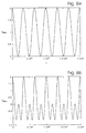
- Fig. 8a and 8b the control signals v ref,a and v ref,b are shown, which are to be used in this case for extracting B 1 and B 3 , when the embodiment according to Fig. 1 not employing product modulation is used.
- Figs. 5a and 5c is shown in a way analogous to Figs. 3a and 3b the absolute values
- a somewhat better confined main lobe is obtained and considerably lower side lobes are obtained in the difference signal compared to the curve in Fig. 3c.
- the control signal v ref , a , b t 2 ⁇ a 0 + a 1 ⁇ cos ( ⁇ m ⁇ t ) + a 2 ⁇ cos ( 2 ⁇ ⁇ m ⁇ t ) ⁇ cos 2 ⁇ k ⁇ ⁇ m ⁇ t
- k is an integer, so that 2k corresponds to k in Eq. (12c)
- ⁇ m is the angular frequency, which corresponds to the modulation frequency f m and where different values of k are selected for each detector.
- the distance dependency of the signal is here represented by both X and T.
- the dependency on T is then filtered away in the envelope detectors 23a, 23b, since for usual approaching velocities v the time dependency of ⁇ 0 T is much more rapid compared to X.
- the detected voltage v kohdet,a,b in (13b) will be more indefinite, when ⁇ 0 T varies. This becomes still more apparent for the case, when several simultaneous reflections exist. If the difference of two envelopes formed from functions of type (13b) is taken, where both sin( ⁇ 0 T) and cos( ⁇ 0 T) are included, these functions do not obtain zeroes for the same values of ⁇ 0 T, which becomes embarrassing for e.g.
- control signals mentioned above to the coherent detector 19a, 19b are only examples of the large extent to which one can influence the appearance of the distance functions in the demodulation by using a linear combination of odd or even overtones of the modulation frequency as a control signal.
- the method as described above comprising that at least two frequency components are detected in each channel can also be used in other radar applications in order to synthesize, using Eq. (10), output signals having completely different properties in regard of a desired distance dependency.
- the signal processing can also be performed digitally, wherein the actual signals are first A/D-converted.
- v ref,a,b (t) and v p (t) in the general case are linear combinations of signals having frequencies corresponding to the modulation frequency f m and overtones thereof one can also implement the algorithm as a procedure consisting of three steps:
- the discrete fourier transforms (DFT), which are calculated in conjunction with the spectral detection in the step (a), can advantageously, in particular in the case where many tones are used in the steps b) and c), be performed by means of some suitable algorithm such as of the type Fast Fourier Transform (FFT).
- FFT Fast Fourier Transform
Landscapes
- Engineering & Computer Science (AREA)
- Radar, Positioning & Navigation (AREA)
- Remote Sensing (AREA)
- Computer Networks & Wireless Communication (AREA)
- Physics & Mathematics (AREA)
- General Physics & Mathematics (AREA)
- Signal Processing (AREA)
- Radar Systems Or Details Thereof (AREA)
Description
- The present invention relates to a device and a method for determining distances, such as in a radar installation, by means of issued and reflected electromagnetic waves, in particular in determining short distances s to a reflecting surface.
- Radar is concerned with detecting and determining distances to objects and for this purpose microwaves within suitable frequency ranges are used, which are also called radar waves. For accurate determination of distances, for example determining short distances to an object, advantageously frequency modulated radar having a continuously issued wave, FMCW-radar is used, which is generally described in the book "Introduction to radar systems", M.I. Skolnik, 2nd ed., McGraw-Hill Book Company 1981, pp. 81 - 98.
- Such a device, which can be both used for determining long or short distances, is disclosed in U.S. Patent US-A 2,907,023 for Skinner. A frequency modulated radar wave is issued having a triangular or sawtooth modulation. Suitable frequency components of the received signal is filtered out at frequencies equal to multiples of the modulation frequency and the amplitudes of these components are compared, which are obtained after removing a rapid sinusoidal dependency on the distance. For equality a control signal can be obtained. However, the comparison has to be made only for amplitude values about some threshold level, which can be difficult to determine. This prior design should be apt to erroneous indication owing to the fact that an issued signal can be reflected against for example a large surface located behind a target, so that a relatively strong received signal reflected from this surface will be detected. When filtering out suitable frequency components amplitudes having a complicated dependency on the distance are obtained, and thus the equality condition used provides little information on the distance. Furthermore, filters which are fixedly tuned to frequencies related to the modulation frequency must be used, what makes it difficult to modify or vary the modulation frequency.
- In Swedish patent application published with No. 435874 for public inspection for Saab-Scama AB, furthermore a radar installation is described, which can be used for determining distances from a movable body. This radar installation employs a continuous transmitter signal, which is sinusoidally frequency modulated and which is mixed with the received echo signal, which has been reflected by a surface. The signal spectrum then obtained comprises among other things a plurality of tones related to the modulation frequency, i.e. signal components having frequencies equal to integer multiples of the modulation frequency. The amplitudes of the tones vary, when the rapid dependency on the distance has been removed, with the distance as Bessel functions Jn of the first kind.
- From this signal spectrum two bands are extracted, both around a predetermined Doppler frequency fd given by the relative velocity v of the radar installation in relation to the target and the wave length (λ) of the radar signal according to fd = 2v/λ, and around the double modulation frequency. The signal strengths in these two frequency bands vary as the absolute value of the Bessel functions J0 and J2 respectively in addition to the rapid periodic dependency on distance as indicated above. Finally a difference signal is formed by taking the difference of these two signals, and this difference signal will then have a rather steeply increasing characteristic, i.e. the level of the output signal will be strongly changed, when the installation is closer to the reflecting target than a predetermined short distance. The difference signal can be further improved by amplifying the signals before forming the difference, so that a weighted difference is produced.
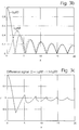
- This prior method is illustrated by Figs. 3a - 3c, where in the diagram in Fig. 3a the Bessel functions J0(X) and J2(X) are shown as depending on a dimensionless quantity X, which is proportional to a distance R, according to

where Δf is the frequency swing in the modulation, for example 10 MHz, and c is the velocity of light. The absolute values of the functions appear from the diagram in Fig. 3b and a difference weighted in a suitable way is shown in the diagram in Fig. 3c, as above as functions of the quantity X. In Fig. 3c the weight factor d = 1.5 is used, and thus the shown function is:
- The figures do not show completely correct pictures since the amplitude of a reflected signal also has a dependency on the distance caused by the signal propagation and also depending on the antenna used and further on the magnitude of the reflecting area. The dependency of the distance can be of different kinds, so that the amplitude of the echo signal can for example be proportional to R-1 or R-2. This means that actually the absolute value of the difference signal decreases more rapidly for large values of X and thus large distances R than what is shown in Fig. 3c. Thus in Figs. 3 and 4 in the cited Swedish patent application curves are shown corresponding to Figs. 3e and 3c, in which the signals have been divided by R, but in the Fig. 3c appended hereto a pure difference is shown without considering any such dependency on the distance.
- According to the above-cited U.S. patent for Skinner it is considered that a desired distance has been achieved, when two amplitudes filtered out agree with each other, i.e. that their difference is equal to zero. A dependent condition could however be that for equality the amplitudes should not be near zero, since else equality is obtained for all common zeroes. Furthermore, rather high multiples of the modulation frequencies are used - the
multiples - In the Swedish patent application published with No. 430537 for public inspection for Svenska Philipsföretagen AB a proximity fuse is disclosed of a kind similar to that disclosed in the cited Swedish patent application for Saab-Scania AB. In the comparison of the results of two branches of a detector assembly a combination of "Doppler components" Da1 - 1/2·Da2 can be used as one signal in the comparison whereas the other signal is Da2 - 1/2·Da3. Here Da1, Da2, Da3 are apparently the functions obtained for sawtooth modulation which correspond to J1, J2, J3 respectively for sinusoidal modulation.
- In U.S. patent 4,660,040 for Grandos target sensing apparatus is disclosed in which a carrier frequency is frequency modulated with a triangular wave and transmitted from a sensor to a target. The signal received from the target is mixed with a portion of the transmitted signal. At least two harmonics of the modulating frequency are filtered from the output of the mixer and they are synchronously detected with an harmonic of the same frequency to obtain a doppler signal that is detected and fed to a comparator.
- As has been indicated above, when the intended target is located in front of a large, strongly reflecting area, from this area a reflected strong signal can be obtained, which is detected simultaneously being superposed on the desired signal. For this large reflecting area the regions in the difference signal derived from the reflected signal thereof, where positive values exist, can obtain so large maximum values that the threshold value is achieved. Then apparently erroneous detection is obtained. The derived amplitudes for a case comprising a plurality of reflected signals received at the same time is in a complicated way dependent on each of the signals.
- An increased security against erroneous detection could be obtained by setting the threshold value at a higher value, such a setting however resulting in an insecure determination of the distance, since the reflected signal is strongly dependent of the target area, see Fig. 3 in the cited Swedish patent application for Svenska Philipsföretagen AB. Actually, one would like to detect on the zero at the lowest distance value, compare the accompanying Fig. 3c. Naturally this is not possible, since there is a plurality of zeroes. A compromise is to set the threshold value at a low value, so that the corresponding distance value always, for target areas or echo surfaces of different magnitudes, is near the intended zero. Then it must be arranged that the function used for a selected threshold value gives a sufficient security against erroneous detection. When selecting function and signal parameters one must consider allowed frequency values and possible signal powers. The function should be selected, so that the maximum values in the mentioned regions having positive values in turn are as small as possible, i.e. very near zero, and so that the regions furthermore are so short as possible, maintaining the general shape of the difference signal.
- In order to obtain functions having the same general appearance as that of the function in Fig. 3c, in particular for small arguments, primarily Bessel functions of low orders and corresponding functions for triangular modulation are to be used, since functions having higher orders have regions comprising maximum absolute values for large arguments, generally in regions, where the argument X approximately is equal to the order of the function, compare Fig. 5 in the cited U.S. patent 2,907,023. This in turn means that the detection of signal components in the received echo signal is to be made at low multiples of the modulation frequency. This gives the additional advantage, that the dependency on R-1 or R-2 assists in reducing the values within the mentioned regions having positive values compared to the values within the region near the argument zero or zero distance, in which the detection is intended to be made. In order to maintain the appearance according to Fig. 3c also the difference signal or one of the signals, from which it is formed, must have a value different from zero at a zero distance, also in the case where the dependency of R-1 and R-2 is omitted.
- In determining short distances proximity sensors are used, which can be designed to provide a signal when the sensors are closer to the target than some predetermined distance. In determining distances from a robot or a similar projectile usually a proximity sensor comprising a radar based distance sensing means of the type as described above and called a proximity fuse is used. The task of the proximity fuse is to ignite, at a predetermined suitable distance from the target, the charge which is carried by the robot or the projectile. It is obvious that the distance, at which the proximity fuse provides its ignition pulse, must be correctly set and also correctly measured which is most important, since an erroneous such setting or an erroneous such measurement completely or partly cancels the intended effect of the robot or the projectile to the target.
- The prior methods as described above have thus significant apparent limitations for example for determination of the distance from a position located elevated in the air to a surface located at low height over the surface of the earth. When a proximity fuse is used at low heights, thus reflections from the underlying ground or an underlying water surface can strongly interfere with the desired signal, i.e. the signal which has been reflected by the intended target. In the worst case it can result in that the signal reflected by the target is completely suppressed or that the proximity fuse is made to trigger an ignition pulse at an erroneous distance.
- When detecting around selected frequencies in principle according to the prior methods first a mixing of the received signal with a leak signal from the transmitter is used. Then band pass filters tuned to suitable frequencies are used, which are multiples of the modulated frequency, and thereupon an envelope detection. The bandpass filters have pass bands having a width corresponding to approximately the Doppler frequency. There a disadvantage exists, in that for a large change of the modulation frequency also the pass band of the tuned filters must be displaced, in particular in the case where higher multiples are to be detected. However, according to the cited Swedish patent application for Saab-Scania AB in one channel, a coherent detection can be made after the filtering around the desired multiple of the modulation frequency. Thereupon the signal is filtered in bandpass filters having pass bands around the Doppler frequency and having upper limit frequencies lower than half the modulation frequency. Then no tuned filters are required, since the corresponding effect is obtained by means of the control signal, which is used in the coherent detection.
- It is an object of the invention to provide radar installations and measuring methods carried out by means of such installations, by means of which determinations of distances can be executed with improved performance compared to what has been possible in the prior art. In particular the object is to prevent that a signal, which indicates that the installation is closer to a target than a predetermined distance, is triggered at an incorrect distance, or to prevent, that a large, non-desired signal from another reflector than the desired one or generally from a reflecting surface outside the target suppresses, dominates or hides the signal originating from the target, i.e. the object is generally to achieve that a small, desired signal, which indicates a distance to a considered target area, can be distinguished in a secure way.
- Thus it is a further object of the present invention to provide radar installations and measuring methods carried out by such installations, by means of which a signal is generated indicating the distance of an intended target, wherein in the signal generation interfering contributions to the signal from sea or ground surfaces located in the vicinity of the target are reduced, such as surfaces located below or behind the target as seen from the radar installation.
- A further object of the present invention is to provide radar installations and measuring methods carried out by means of such radar installations, by means of which a signal is generated indicating the distance to an intended target, in which the influence of interfering contributions to the signal from repeating interfering transmitters can be removed or in any case efficiently reduced.
- A radar installation is thus provided in which reduced distance side lobes outside the detection area of a radar installation are obtained, in regard of the distances of different targets/surfaces.
- The desired shape of the signal which is to be formed in a radar installation and which indicates the distance of an intended target, corresponds, according to the discussion of the prior art above, ideally to a function, which has values equal to zero for distances larger than some minimum distance and which has substantially infinite, positive values for distances smaller than the minimum distance, i.e. for distances decreasing below the minimum distance the values of the function increase very strongly. For such a function one can determine a suitable threshold value according to the discussion above, so that precisely when the function exceeds this value, one has with a large security come closer to a considered target than a minimum distance, so that the real distance then has not had time to decrease to a value too far below the minimum distance for commonly used approaching velocities. The value zero for larger distances, which in the known procedures corresponds to the repeated zeroes according to the discussion above, can furthermore be used for determining the zero level, from which the threshold value is to be counted or referred. The known functions of Bessel type or the corresponding type for triangular modulation are modified, so that the obtained signal still more resembles the ideal signal shape. The maximum values in said regions having positive values are made as small as possible and these regions are made as short as possible. The desired modification is achieved by using in principle the same procedure as in the above cited Swedish patent application for Saab-Scania AB and by forming in at least one of the channels a suitably chosen linear combination of Bessel functions or corresponding functions for other modulation cases. The linear combination is a combination of either only even or only odd Bessel functions or corresponding functions, most frequently of Bessel functions and corresponding functions of low order according to the discussion above.
- Generally thus, for example signals having amplitudes corresponding to suitable chosen linear combinations of Bessel functions can be detected, which for distances larger than the minimum distance, i.e. for distances larger than the smaller zero, increases more rapidly with the distance then the combination of J0 and J2, which is described in the above cited patent application SE 6713687-9. This results in that the threshold value can be determined with larger security, so that it will be more difficult for interfering signals and noise to affect the signal and so that the detection that the sensing installation is closer to a target than the minimum distance becomes more secure.
- Furthermore, in the frequency modulation in the known way a triangular modulation shape can be used instead of a sinusoid shape, which results in that the amplitude of the overtones of the modulation frequency after the mixer of the receiver will not longer follow Bessel functions of the first kind but instead other functions, which in their appearance resemble the Bessel functions of the first kind but which has regions decreasing more rapidly with the distance, i.e. the envelopes of the obtained functions increase more rapidly with the distance than the envelopes of the corresponding simple Bessel functions. If according to the discussion above linear combinations of different tones of the functions are created in the receiver, which functions arise when the transmitted frequency modulated signal for triangular modulation is mixed with the received reflected signal, further improvements as to the dependency on the distance can be obtained.
- In the purpose of even more safeguard, that in the proximity fuse application ignition pulses are triggered at incorrect distances in the case where interferences in the shape of repeating interfering transmitters exist, the transmitted signal can be modulated by a modulation signal having a frequency varying in time, such as that the frequency or phase of the modulation signal is controlled by a noise signal. As an alternative thereto the modulation frequency can be changed with time according to some predetermined, more or less complicated pattern, which is hard to predict.
- Additional objects and advantages of the invention will be set forth in the description which follows, and in part will be obvious from the description, or may be learned by practice of the invention. The objects and advantages of the invention may be realized and obtained by means of the methods, processes, instrumentalities and combinations particularly pointed out in the appended claims.
- While the novel features of the invention are set forth with particularly in the appended claims, a complete understanding of the invention, both as to organization and content, and of the above and other features thereof may be gained from and the invention will be better appreciated from a consideration of the following detailed description of nonlimiting embodiments presented hereinbelow with reference to the accompanying drawings, in which:
- Fig. 1 is a block diagram of a radar device in a proximity fuse,
- Fig. 2 is a block diagram of an alternative radar device in a proximity fuse,
- Fig. 3a is a diagram showing two Bessel functions of the first kind,
- Fig. 3b is a diagram showing curves of the absolute value of the Bessel functions in Fig. 3a,
- Fig. 3c is a diagram showing a weighted difference of the two curves in Fig. 3b,
- Fig. 4a is a diagram showing two other functions, which are another kind and resemble Bessel functions,
- Fig. 4b is a diagram showing curves of the absolute value of the functions in Fig. 4a,
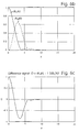
- Fig. 4c is a diagram showing a weighted difference of the two curves in Fig. 4b,
- Fig. 5a is a diagram showing two linear combinations of Bessel functions,
- Fig. 5b is a diagram showing curves of the absolute value of the functions in Fig. 5a,
- Fig. 5c is a diagram showing a weighted difference of the two curves in Fig. 5b,
- Fig. 6a is a diagram showing two linear combinations of functions which are the kind illustrated in Fig. 4a,
- Fig. 6b is a diagram showing curves of the absolute value of the functions in Fig. 6a,
- Fig. 6c is a diagram showing a weighted difference of the curves in Fig. 6b,
- Figs. 7a is a diagram showing examples of wave forms, which can be used in triangular and saw tooth shaped modulation respectively, and
- Figs. 8a and 8b are diagrams showing examples of control signals to coherent detectors.
- In Fig. 1 a radar device for determining the distance of a target is shown as a block diagram. In a
transmitter 1 is generated, in anoscillator 2 included therein, a periodic signal having a base or carrier frequency f0 suitably within the microwave range (typically 1 - 3 GHz) and this signal is frequency modulated by means of a signal from afunction generator 3, such as by making the signal directly control the frequency of theoscillator 2, which can be the type VCO. Furthermore, anantenna 5 is included in thetransmitter part 4 of the radar device, the antenna being connected to thetransmitter 1. On theantenna 5 the frequency modulated signal is issued as an electromagnetic wave in order to be reflected against an intended target indicated at 6. - The same signal, which is issued, is also directly transferred as a leak signal on a
line 7 as a first input signal to amixer 9, which is arranged in thereceiver part 11 of the radar installation. Electromagnetic waves including that wave, which is constituted by the wave which is issued and then is reflected by sometarget 6, together with various other waves such as noise and similar things are received by anantenna 13 in thereceiver part 11. The electric signal received by theantenna 13 is conducted as a second input signal to themixer 9. The output signal of themixer 9 is then transferred to abandpass filter 15 and thereupon to anamplifier 17. - Thereupon the further signal processing in the
receiver part 11 is executed in two parallel channels, illustrated at a and b. These channels comprise each acoherent detector bandpass filter amplifiers envelope detectors - The respective signals output from the two
envelope detectors difference forming device 27 in which the difference of the two output signals is produced in a predetermined, weighted way. Thedifference forming device 27 provides an output signal on aline 29, which output signal is used, such as after suitable processing, for example after filtering in afilter 30 or after passing a discriminator, not shown, in the further signal processing, such as for determining the time, when the radar device, if it is used as a proximity fuse, is to provide its ignition pulse. - In this first preferred embodiment, which is illustrated by the block diagram in Fig. 1, in a first case the
transmitter 1 is assumed to be frequency modulated by a sinusoid signal wave. Thus thefunction generator 3 is assumed to provide a sinusoid output signal having a frequency fm, with which the signal having the carrier frequency f0 is modulated, which is to be transmitted on theantenna 5. The transmitted electromagnetic wave is reflected by some reflecting surface of an intendedtarget 6, which is located at a distance R, which one wants to find, from theantennas antenna 13, which, if desired, can be identical to thetransmitter antenna 5. This condition can also be termed in the way that some delay T exists between the corresponding electric signals, which are fed to themixer 9. This delay T is proportional to the distance R from theantennas target 6 according to the relation T = 2R/c, where c is the velocity of light. Furthermore, if theantennas target 6, the frequency of the signal is offset by an amount equal to the Doppler frequency. - The signal received on the
antenna 13 and the signal, which has been transferred directly from the frequency modulatedtransmitter 1 through theline 7 to thereceiver 11, are thus both conducted to themixer 9 in order to be mixed in a suitable way therein. The signal output from themixer 9 is then conducted to thebandpass filter 15, which is designed to filter away interfering signals and other, non desired signal components, such as the carrier frequency. Thebandpass filter 15 is then designed to let frequencies through up to and including the highest desired overtone of the modulation frequency, e.g. up to and including the sixth overtone, i.e. the upper limit frequency of the filter can be located at 6.5 fm, but suppresses signals above this frequency. The lower limit frequency is selected, so that frequencies corresponding to the lowest calculated Doppler frequency do not vanish. From thebandpass filter 15 the filtered signal is conducted to anamplifier 17 and is amplified therein to a level suited for the continued processing. The signal processing is then made in parallel in the parallel channels a and b respectively. - First in these parallel channels a coherent detection is made in the
blocks blocks lines function generator 3 in thetransmitter part 4 of the radar installation. The control signals vref,a and vref,b respectively consist of a sum of sine tones, which have predetermined phase positions and amplitudes. These sine tones have frequencies, which are multiples of the modulation frequency fm. In the simplest case they consist only of a single sine tone. Examples of sums of sine tones are given by Eq. (12c) hereinbelow. - Thereupon bandpass filtering of the coherently detected signals is made in the two
filters Doppler filters - The filtered signals are amplified in the
amplifiers envelope detector envelope detectors bandpass filters device 27. The summingdevice 27 is arranged, so that the signal from the channel b is given an inverted sign, whereby the output signal from the summingdevice 27 actually becomes a difference of the two input signals. By means of this generation of a difference, using suitable control signals and weights it can be obtained, that the output signal obtains a well confined distance range, in which it has a positive sign, which is called the target detection range. Outside this range the different signals have a negative sign or very small positive values and a target detection can therefore effectively be suppressed outside this range, as will be demonstrated hereinbelow. - Furthermore, in the summing
device 27, as has been indicated above, an amplifying of the two input signals can be made, which can be different for the respective input signal. Thereby an arbitrary weighted difference of the two input signals can be produced. A weighting can also be obtained by the fact that the components in each branch, for example theamplifiers difference forming device 27. - Using this construction it is obtained, that functions which do not only use J0 and J2, can be used for forming a linear combination in a channel. In a channel an arbitrary linear combination of tones corresponding to amplitudes of different Bessel functions can be detected. This results in, possibly together with the fact that more than two channels are used, what of course requires a more complicated production of a difference or a sum of the resulting signals, that a signal having a steep characteristic, i.e. having monotonously, strongly increasing positive values for decreasing distances from the target and including very small positive peaks outside the proximity region of the target can be obtained at the output terminal of the summing device, so that the risk that a charge is triggered owing to the fact that an incorrect distance has been measured is made considerably smaller. Using suitable control signals to the coherent detectors only a simple difference has to be formed in the summing
device 27. - In the purpose of further improving the suppression of the side lobes of the obtained functions, which are constituted by Bessel functions according to the discussion above, which side lobes increase with distance, i.e. in order to achieve, that the peaks of the obtained functions beside the main lobe are kept as small as possible, one can instead of modulating the transmitter signals sinusoidally use triangular modulation, as is proposed in e.g. the U.S. patent cited above. An example of the signal shape used in triangular modulation is illustrated by the curve in the diagram in Fig. 7a, in which a somewhat asymmetric triangular shape is shown, which has decreasing rectilinear portions, which are somewhat steeper than the increasing rectilinear portions.
- In the case where this form of modulation is used, the amplitudes of the tones in the signal spectrum, which the signal after the
mixer 9 has, do not any more follow the Bessel functions of the first kind, Jn. Instead the amplitudes are functions of another type, which in their appearance resemble the Bessel functions but among other things, which in this application is of great importance, differ from them by the fact that their side lobes in relation to the main lobe decrease more rapidly with the distance than in the corresponding case for usual Bessel functions. - Furthermore, it turns out, see also in this case e.g. the above-cited U.S. patent, that also sawtooth modulation results in functions, the side lobes of which in relation to the main lobe decrease more rapidly than the side lobes of the corresponding Bessel functions in relation to the respective main lobe. Thus also sawtooth modulation could advantageously be used. An example of the modulation function used in sawtooth modulation is illustrated by the curve in Fig. 7b, which has rectilinear decreasing portions, which are practically perpendicular to the time axis.
- In Fig. 2 another preferred embodiment is illustrated. This embodiment agrees in its general construction with the embodiment illustrated in Fig. 1 except that a
product modulator 35 is arranged between the output of theamplifier 17, which is connected after themixer 9, and the division into channels. The individual included components can however be different in the two embodiments. - The
product modulator 35 is introduced in the purpose of concentrating the power spectrum of the obtained signal. It is made in such a way that the output signal of the mixer, the power spectrum of which consists of peaks around the modulation frequency and multiples thereof, by product modulation with a suitable signal, e.g. a tone having a frequency equal to the modulation frequency fm, is modulated in order that thereby a signal will be obtained having a power spectrum, which has a larger portion of its energy around those frequencies which are to be filtered out in the following signal processing. To the spectrum of the signal thus no new frequencies are added, but only a redistribution of the power of the frequencies included in the spectrum is made. - The
product modulator 35 can be implemented as a coherent detector, the reference signal vref,p of which is related to the modulation frequency fm and the overtones thereof. - As a reference signal to the
product modulator 35 in this embodiment the signal vref,p is used, which in the same way as the signals vref,a and vref,b is generated by thefunction generator 3 in thetransmitter part 4 of the installation and which is transferred to theproduct modulator 20 on aline 37. The signal vref,p consists in the general case of a sum of different sine tones having predetermined phases and predetermined amplitudes, and these sine tones in the signal spectrum of the signal vref,p have frequencies, which are multiples of the used modulation frequency fm, see also hereinbelow. - In this embodiment also the signal spectra of the control signals vref,a and vref,b, which are used in the coherent detection in the
detectors - Generally it can be said that the control signals for the purpose which is here aimed at, i.e. that the output signal of the summing
device 27 for such distances d, which are longer than a distance somewhat exceeding the distance, at which the charge is to be triggered, shall have as small absolute values as possible or generally all the time be as near a constant value, the zero level, as possible, should be selected either, so that both are odd multiples of the modulation frequency fm or so that both of them are even multiples of the modulation frequency fm. It can also be advantageous, in order to achieve that the positive values in the isolated regions for larger distances will be as small as possible, to use, as has been indicated above, the signal strengths around more than two signals in the signal spectrum and then to form, by means of the summingdevice 27, a weighted difference thereof. In this case more channel branches than two can be used in order to produce more tones in the spectrum. The most interesting linear combination of the tones of the output signal of the mixer is as above produced by means of the product modulation and the coherent detection and the choice of control signals thereto. - In a third preferred embodiment, which is a development of the two embodiments described in conjunction with Figs. 1 and 2, the
function generator 3 is controlled by anauxiliary unit 37 for a suitably rapid, random variation of the frequency of the modulation signal, however the magnitude of the modulation being maintained constant. Theauxiliary unit 37 can as an essential element comprise anoise generator 39. It can consist of an analogous noise source, the signal of which is filtered in a suitable bandpass filter, or of a pseudo-random generator, e.g. in the shape of a shift register which is connected to use feedback in a suitable way and which is clocked by a suitable frequency. The output signal from thenoise generator 39 controls a voltage controlledoscillator 41, VCO ("Voltage Controlled Oscillator"). The output signal then obtained is divided by a factor N in ablock 43 and in thefunction generator 3 the complete modulation signal is generated. In theblock 3 as above the multiples of the modulation frequency are generated, which are required for the control signals vref,a, vref,b and vref,p respectively. - The advantage of this embodiment is, that the modulation is not any longer totally periodic, as seen over time intervals having a relatively large length in the considered situation, and thus changes its period time or equivalently thereto its frequency all the time, so that it however at each instant can be assumed to have a definite frequency fm(t), which is a function of the time t. It results in that for example a repeating interfering transmitter cannot any longer produce false ignition pulses. By the fact that the issued signal and the overtones thereof are all the time used as reference signals in the
coherent detectors product modulator 20 respectively thereceiver part 11 will all the time work in the same rate as thetransmitter part 4. - In the purpose of providing a better understanding of the radar installation the operation thereof will now also be mathematically described.
- The signal issued from the
transmitter 5 of the radar installation is assumed to be frequency modulated by a periodic or near-periodic signal f(t). The signal issued by theantenna 5 can then be described by
where the phase modulation φ(t) is given by
- The signal received by the
antenna 13 from atarget reflector 6 at the distance R is delayed by the time T = 2R/c, and can then be written
- After having passed the
mixer 9 and thebandpass filter 15 the signal is
- If the phase modulation is periodic, also vm(t) is periodic and can be developed in a Fourier series. The corresponding expansion can be approximately made for near-periodic modulation provided that the deviations from the periodic modulation have a time constant, which is much larger than the period time of the frequency modulation.
- The deviation from a completely periodic phase modulation can be included in Eq. (1), if φ0 is replaced with φb(t) in Eqs. (1) and (2). The output signal of the mixer is in this case

where Δφb(t,T) = φb(t) - φb(t - T) - By selecting φb(t) in some suitable way it is obtained that Δφb(t,T) → 0 or ≈ 0, when the measuring distance R is short. This condition is satisfied in the proximity fuse application. At long measuring distances or for repeating interfering transmission at longer distances the phase noise modulation φb(t) will in contrast have a full effect. A purpose of the radar installation is thus to achieve a neglectable influence of the noise modulation within a proximity region of the target, the noise modulation at the same time strongly distorting the response from repeating interfering transmitters at longer distances.
- For symmetric triangular modulation using the modulation frequency fm and the frequency swing Δf for the bandpass filtered output signal of the mixer is obtained


- In the proximity fuse application the modulation frequency fm is selected to be so low, that the phase angle φm ≈ 0 in the distance interval of interest.
- The argument X is related to the distance R of the reflector and the frequency swing Δf according to

- For sinusoidal frequency modulation using

the coefficients A2k(X) are replaced by (-1)kJ2k(X) and
the coefficients A2k-1(X) are replaced by (-1)kJ2k-1(X),
where Jn denotes Bessel functions of the first kind and the argument X instead is given by
- The appearance of the functions Jn(X) and An(X) is seen in Figs. 3a and 4a respectively for the values n = 0 and n = 2, in which the curve for n = 0 is drawn in a solid line whereas the curve for n = 2 is drawn using a dashed line. A frequency swing Δf = 10 MHz is assumed. It should be observed that the unit X on the ordinate axis in different ways depends on the target distance R. As appears thereof, considering the different graduation on the ordinate axis, A0(X) and A2(X) have approximately as well confined main lobes as J0(X) and J2(X) respectively, i.e. their first lobe or region having the first extreme value, when X increases from zero to positive values, have approximately equally large extensions in the X-direction, as appears from the diagrams of the absolute values in Figs. 3b and 4b. In contrast, A0(X) and A2(X) have lower side lobes decreasing more rapidly with the distance than the Bessel functions Jn(X), i.e. the extremal values for A0(X) and A2(X) for higher X-values have smaller absolute values than the absolute values of the extremal values within the corresponding regions of J0(X) and J2(X) respectively. The corresponding is also true for other values of n, i.e. An(X) has generally an approximately equally well confined main lobe (the lobe closest to X = 0) and lower side lobes. For this reason triangular modulation is to be preferred to sinusoidal modulation and triangular modulation will produce a better result, if it for example is applied in the procedure described in the above-cited Swedish patent application for Saab-Scania AB. In Fig. 4c a weighted difference having the same weighting factor d as in Fig. 3c of the functions |A0(X)| and |A2(X)| is shown, i.e. |A0(X)| - 1,5·|A2(X)| is here shown, from which the advantage of triangular modulation clearly appears.
- Generally one can synthesize new functions having desired properties by detecting coherently individual tones in each channel for a number of different selected frequencies kfm, where k are selected as different non-negative integers, k = 0, 1, 2, ..., and then for sinusoidal modulation form a linear combination of the amplitudes of the detected tones

where the sum is taken over the selected k-values and the coefficients ak are selected in a suitable way. In the corresponding way for triangular modulation a suitably selected linear combination
- What is tempted at, when the radar installation is used as a proximity sensor, i.e. for detecting small short distances, is that the value of the signals will be large within a limited distance interval from the target and that the signal values outside this interval should be as small as possible. In the block diagram of the radar installation according to Fig. 1 one can primarily effect the selection of tones, which are combined, and then the distance dependency of the output signals of the channels by selecting different control signals vref,a, vref,b to the
coherent detectors - By studying Figs. 4a and 4b and the corresponding curves Ak(X) and |Ak(X)| for other integer values k it is realized, that a side lobe suppression better than for the individual functions An(X) can be obtained already by adding two functions Bk(X) = Ak-1(X) + Ak+1(X), i.e. using only two terms in the sum according to (10b), which are given the same weight. In that way the detection in a channel will approximately correspond to the total detection (observe that |J0| - |J2| = J0 + J2 within a limited interval near the distance of zero) according to the cited Swedish patent application for Saab-Scania AB, even if there a sinusoidal modulation is used. In Fig. 6a the obtained linear combination for k = 1, the curve B1 drawn in a solid line, and k = 3, the curve denoted by B3 drawn in a dashed line, is shown. In Figs. 6b and 6c the curves are illustrated, which are obtained from these in the same way as the curves in Figs. 4b and 4c have been obtained from Fig. 4a, i.e. in Figs. 6b and 6c the absolute values |B0(X)| and |B2(X)| and the weighted difference |B0(X)| - 1.5·|B2(X)| respectively are shown. A better confined main lobe is obtained and side lobes having reduced amplitudes are obtained in the difference signal compared to the curve in Fig. 3c.
- In Fig. 8a and 8b the control signals vref,a and vref,b are shown, which are to be used in this case for extracting B1 and B3, when the embodiment according to Fig. 1 not employing product modulation is used. The curves are drawn for the modulation frequency fm = 150 kHz. According to the discussion above then the following relation is true for the control signals (k = 1 and k = 3):


- In Fig. 5a curves are shown corresponding to those in Fig. 6a for sinusoidal modulation, i.e. curves which have been obtained by adding two Bessel functions, and there thus the curves Ck(X) = Jk-1(X) + Jk+1(X) for k = 1 for the curve denoted by C1 drawn in a solid line and for k = 3 for the curve C3 drawn in a dashed line. In Figs. 5a and 5c is shown in a way analogous to Figs. 3a and 3b the absolute values |C0(X)| and |C2(X)| and the weighted difference |C0(X)| - 1,5·|C2(X)|. A somewhat better confined main lobe is obtained and considerably lower side lobes are obtained in the difference signal compared to the curve in Fig. 3c.
- The obtained improvement in the selected example can also be demonstrated analytically for sinusoidal modulation, since the following mathematic relation is true

- When X increases, thus the sum decreases more rapidly than the individual Bessel functions, the envelope of which decreases asymptotically as X-1/2.
- Similar results can be derived for triangular modulation, if starting from Eq. (6).
- From Eq. (5) it is realized that one can also produce the function Bk(X) for the case of triangular modulation by multiplying the output signal from the
mixer 5 with the following signal, which can be performed in the product modulator 36 in the embodiment according to Fig. 2:

- In the case of triangular modulation of course directly from the output signal vm(t) of the
mixer 9 according to Eq. (5) Bk(X) can be extracted, if one instead of a single sinusoidal control signal vref,a, vref,b to thecoherent detector 
coherent detectors - The control signal

where k is an integer, so that 2k corresponds to k in Eq. (12c), can for example be used to each coherent detector, where ωm is the angular frequency, which corresponds to the modulation frequency fm and where different values of k are selected for each detector. From the relation (5) for φm = 0 for triangular modulation after aDoppler filter 
- The distance dependency of the signal is here represented by both X and T. The dependency on T is then filtered away in the
envelope detectors - If terms comprising sin(ω0T) and cos(ω0T) are included at the same time, the detected voltage vkohdet,a,b in (13b) will be more indefinite, when ω0T varies. This becomes still more apparent for the case, when several simultaneous reflections exist. If the difference of two envelopes formed from functions of type (13b) is taken, where both sin(ω0T) and cos(ω0T) are included, these functions do not obtain zeroes for the same values of ω0T, which becomes embarrassing for e.g. the desired appearance of the distance function for the application as a proximity sensor, when it is required, that the difference signal > 0 for X < X0, where X0 is a not too small distance value, and all values of ω0T are in the interval [0 - 2π].
- The control signals mentioned above to the
coherent detector - More generally the control signal of the
coherent detectors 
where the sum is taken for values of n, which are either a selection of only evenintegers odd integers - From Eqs. (12c), (13a) and (14) it is realized, that one can also execute the procedure in two steps according to the embodiment in Fig. 2:
- a) first a product modulation of the mixer signal using vref,p(t) = nΣancos(2πnfm) as a control signal and thereupon
- b) detecting the signal components which are then newly formed and which are dependent on the distance, at the overtone kfm by coherent detecting using cos(kωmt) as a control signal vref,a and vref,b to the
detector - From Fig. 5c (compare also Fig. 3c), for the case of sinusoidal modulation the improvement of the side lobe suppression is observed, which is obtained using the procedure described above comprising the reference signal vref,p = sin(2πfmt) fed to the
product modulator 35. The corresponding improvement appears from Fig. 6c compared to Fig. 4c for a case of triangular modulation and the reference signal vref,p according to Eq. (12a). - From Figs. 3c, 4c, 5c and 6c, in which a sinusoidal modulation is shown in Figs. 3c and 5c and triangular modulation is shown in Figs. 4c and 6c, it appears that a demodulation according to what has been proposed above including detecting at least two frequencies in each channel combined with triangular frequency modulation strongly improves the performance which has been previously obtained. Also, sawtooth modulation gives similar improvements of the side lobe suppression. The method described above furthermore gives a large freedom in influencing the appearance of the distance functions by means of the signal processing in the receiver by for example influencing the side lobe suppression as has been demonstrated above.
- The method as described above comprising that at least two frequency components are detected in each channel can also be used in other radar applications in order to synthesize, using Eq. (10), output signals having completely different properties in regard of a desired distance dependency.
- The signal processing can also be performed digitally, wherein the actual signals are first A/D-converted. In the digital signal processing, in the general case including product modulation for detecting the k:th overtone

- Since vref,a,b(t) and vp(t) in the general case are linear combinations of signals having frequencies corresponding to the modulation frequency fm and overtones thereof one can also implement the algorithm as a procedure consisting of three steps:
- a) First the different tones Ak(X) according to Eq. (5) are coherently detected in the frequency spectrum.
- b) Then a linear combination is formed, which has desired properties according to the discussion above, by:

- c) Finally a continued signal processing is executed, for example in the shape of envelope detection followed by producing a difference of two of the tones, as is illustrated by Figs. 5c and 6c, which according to the discussion above show the results of forming a difference of envelopes of the signals obtained in the two channels.
- The discrete fourier transforms (DFT), which are calculated in conjunction with the spectral detection in the step (a), can advantageously, in particular in the case where many tones are used in the steps b) and c), be performed by means of some suitable algorithm such as of the type Fast Fourier Transform (FFT).
Claims (31)
- A device for determining distances by means of electromagnetic waves, the device comprising:- a transmitting part (4) having a transmitter (1) arranged to provide a transmitter signal (vs), the frequency of which is modulated by a modulating signal having a modulation frequency (fm),- a receiving part (11) comprising a mixer (9) for mixing a portion of the transmitter signal directly transferred from the transmitting part to the receiving part with an echo signal (vr) received from a reflecting surface (6),- two parallel signal processing channels (a, b) connected to the mixer to receive signals from the mixer,- - a first one of the two parallel signal processing channels arranged to detect, in the signals received from the mixer, signals around first frequencies, and- - a second one of the two parallel signal processing channels arranged to detect, in the signals received from the mixer, signals around second frequencies,so that from each of the parallel signal processing channels a detected signal is obtained, and- an evaluation circuit (27, 31), inputs of which are connected to outputs of the two parallel signal processing channels to receive the detected signals, the evaluation circuit arranged to generate from the received signals an output signal, which is a measure of the extent to which the detected signals agree with each other,characterized in that the first frequencies comprise only frequencies around even multiples of the modulation frequency (fm) and the second frequencies comprise only signals having frequencies around odd multiples of the modulation frequency, so that one of the first and second parallel signal processing channels is arranged to detect only signals having frequencies around even multiples of the modulation frequency and the other of the first and second parallel signal processing channels is arranged to detect only signals having frequencies around odd multiples of the modulation frequency.
- A device according to claim 1, characterized in that the first frequencies and/or the second frequencies are arranged to comprise only a first multiple of the modulation frequency (fm), therein included the multiple 0, for the first frequencies and a second multiple of the modulation frequency, where the order numbers of the multiples has a difference equal to 2.
- A device according to any of claims 1 - 2, characterized by a product modulator (35) connected in series after the mixer (9) of the receiving part (11) to receive signals from the mixer, the two parallel processing channels (a, b) receiving the signals from the mixer after having passed the product modulator.
- A device according to claim 3, characterized by a reference signal line directly connecting the transmitting part (4) and the product modulator (35).
- A device according to claim 4, characterized by means (3) in the transmitting part (4) for providing via the reference signal line a reference signal (vref,p) comprising a weighted sum of sine signals to the product modulator (35).
- A device according to claim 5, characterized in that the means (3) are arranged to provide reference signals having frequencies, which are multiples of the modulation frequency (fm).
- A device according to any of claims 4 - 6, characterized in that each of the parallel signal processing channels (a, b) is arranged to detect, in the signals received from the product modulator (35), signals having only a single frequency.
- A device according to any of claims 1 - 7, characterized in that each of the parallel signal processing channels (a, b) comprise a coherent detector (19a, 19b).
- A device according to claim 8, characterized in that the coherent detectors (19a, 19b) are arranged to use reference signals (vref,a, vref,b), which originate from and are directly transferred from the transmitting part (4).
- A device according to claim 9, characterized in that the transmitting part (4) comprises means (3) for providing reference signals comprising a weighted sum of different sine signals.
- A device according to claim 10, characterized in that the means (3) are arranged to provide reference signals, which have frequencies, which are multiples of the modulation frequency (fm).
- A device according to any of claims 1 - 11, characterized in that the transmitting part (4) comprises means (3, 37) for producing a modulating signal, the modulation frequency (fm) and/or the phase of which is varying in time.
- A device according to claim 12, characterized in that the means (3, 37) for producing a modulating signal comprises a noise generator (39).
- A device according to any of claims 1 - 13, characterized in that the evaluation circuit comprises a summing device (27), inputs of which are connected to outputs of the parallel signal processing channels (a, b) and which is arranged to generate an output signal, which is a linear combination of the detected signals.
- A device according to any of claims 1 - 14, characterized in that the transmitter (1) comprises an oscillator (2) controlled by a function generator (3), which is arranged to provide a modulation signal having a triangular shape or sawtooth shape, so that in providing the frequency modulated transmitter signal (vs) this is triangularly or sawtooth modulated.
- A method of determining distances by issuing electro-magnetic waves having a carrier frequency (f0), the method comprising the steps of:- producing a modulating signal having a modulation frequency (fm),- modulating the frequency of a signal having the carrier frequency with the modulating signal to produce a frequency modulated signal (vs),- issuing the frequency modulated signal as electromagnetic waves,- receiving an echo-signal of the electromagnetic waves to produce a received signal (vr),- mixing (9) a leak-signal of the frequency modulated signal with the received signal to produce a mixed signal,- detecting (a, b) in the mixed signal first signals having frequencies around first frequencies and second signals having frequencies around second frequencies to produce detected signals, and- generating (27, 30) an evaluation signal from the detected signals,characterized in that in detecting the first and second signals in the mixed signal, the first frequencies are taken to comprise only signals having frequencies around even multiples of the modulation frequency (fm) and the second frequencies are taken to comprise only signals having frequencies around odd multiples of the modulation frequency.
- A method according to claim 16, characterized in that in detecting the first and second signals in the mixed signal, the first frequencies or the second frequencies are taken to comprise only a first multiple of the modulation frequency (fm), included therein the multiple 0, for the first frequencies and a second multiple of the modulation frequency, where the order numbers of the multiples have a difference equal to the number 2.
- A method according to any of claims 16-17, characterized by the additional steps of:- producing (3) a reference signal (vref,p), and- product modulating (35) the mixed signal with the reference signal in or before detecting (a, b) the first and second signals.
- A method according to claim 18, characterized in that in the step of producing (3) the modulating signal, the reference signal (vref,p) is also produced.
- A method according to any of claims 18 - 19, characterized in that in the step of producing (3) the reference signal (vref,p), the reference signal is produced to comprise a weighted sum of periodic signals.
- A method according to any of claims 18 - 20, characterized in that in the step of producing (3) the reference signal (vref,p) the periodic signals are selected to have frequencies, which are multiples of the modulation frequency (fm).
- A method according to any of claims 18 - 21, characterized in that in the step of detecting (a, b) the first signals and the second signals, the first signals and/or the second signals are detected by detecting only a single frequency in the signal that has been product modulated (35).
- A method according to any of claims 16 - 22, characterized in that in the step of detecting (a, b) the first signals and the second signals, the first signals and/or the second signals are detected by coherent detection (19a, 19b).
- A method according to claim 23, characterized in that in the coherent detection (19a, 19b), reference signals (vref,a, vref,b) are used, which are produced in the step of producing (3) the modulating signal.
- A method according to any of claims 23 - 24, characterized in that in the step of producing (3) the reference signals the reference signals are produced to comprise a weighted sum of different sine signals.
- A method according to claim 25, characterized in that in the step of producing (3) the reference signals the reference signals are produced to have frequencies which are multiples of the modulation frequency (fm).
- A method according to any of claims 25 - 26, characterized in that in the step of producing (3, 37) a modulating signal the modulation frequency (fm) is produced to be varying in time.
- A method according to claim 27, characterized in that in the step of producing (3, 37) a modulating signal, the modulation frequency is generated by converting (41, 43) a noise signal (39) to a signal having a suitable frequency and power spectrum.
- A method according to any of claims 16 - 28, characterized in that in the step of generating an evaluation signal a linear combination of the two detected signals is generated (27).
- A method according to claim 29, characterized in that the linear combination is a weighted difference.
- A method according to any of claims 16 - 30, characterized in that in the step of producing (3) a modulating signal the modulation signal is produced to have a triangular shape or sawtooth shape.
Applications Claiming Priority (3)
| Application Number | Priority Date | Filing Date | Title |
|---|---|---|---|
| SE9700724 | 1997-02-28 | ||
| SE9700724A SE519095C2 (en) | 1997-02-28 | 1997-02-28 | Method and apparatus for spacing by electromagnetic waves |
| PCT/SE1998/000362 WO1998038526A2 (en) | 1997-02-28 | 1998-02-27 | Method and device for determining distances |
Publications (2)
| Publication Number | Publication Date |
|---|---|
| EP0965053A2 EP0965053A2 (en) | 1999-12-22 |
| EP0965053B1 true EP0965053B1 (en) | 2007-01-24 |
Family
ID=20405972
Family Applications (1)
| Application Number | Title | Priority Date | Filing Date |
|---|---|---|---|
| EP98908388A Expired - Lifetime EP0965053B1 (en) | 1997-02-28 | 1998-02-27 | Method and device for determining distances |
Country Status (6)
| Country | Link |
|---|---|
| EP (1) | EP0965053B1 (en) |
| DE (1) | DE69836955T2 (en) |
| ES (1) | ES2280091T3 (en) |
| NO (1) | NO994152L (en) |
| SE (1) | SE519095C2 (en) |
| WO (1) | WO1998038526A2 (en) |
Families Citing this family (3)
| Publication number | Priority date | Publication date | Assignee | Title |
|---|---|---|---|---|
| DE19850749C1 (en) * | 1998-11-04 | 2000-03-30 | Eckart Hiss | Inductive proximity sensor for detecting metal objects; has signal from detector coil and generator coil input to mixer |
| EP2267477A1 (en) | 2009-06-17 | 2010-12-29 | Nederlandse Organisatie voor toegepast -natuurwetenschappelijk onderzoek TNO | A method for detecting a distance, a radar system and a computer program product |
| JP7069643B2 (en) * | 2017-11-06 | 2022-05-18 | 日本電気株式会社 | Signal processing equipment, signal processing methods and signal processing programs |
Family Cites Families (8)
| Publication number | Priority date | Publication date | Assignee | Title |
|---|---|---|---|---|
| US2907023A (en) * | 1955-04-27 | 1959-09-29 | Leo V Skinner | Ground clearance indicator |
| US4232314A (en) * | 1958-10-28 | 1980-11-04 | The United States Of America As Represented By The Secretary Of The Navy | FM Autocorrelation fuze system |
| US3913103A (en) * | 1959-01-27 | 1975-10-14 | Us Navy | Device for range cut-off by frequency selection in multiple modulation fuzes |
| SE435874B (en) * | 1967-10-06 | 1984-10-22 | Saab Scania Ab | ZONROR OR SIMILAR DEVICE INCLUDING A SINUS MODULATED FM-CW RADAR |
| US4389649A (en) * | 1980-10-14 | 1983-06-21 | The United States Army As Represented By The Secretary Of The Army | Dual channel correlator for an FM-CW ranging radar |
| SE430537B (en) * | 1982-04-06 | 1983-11-21 | Philips Svenska Ab | Frequency modulated Doppler proximity fuse for projectiles |
| FR2581765B1 (en) * | 1985-05-09 | 1987-06-19 | Snecma | ELECTROMAGNETIC SHORT DISTANCE MEASUREMENT SYSTEM |
| US4660040A (en) * | 1985-07-08 | 1987-04-21 | Magnavox Government And Industrial Electronics Company | Target range sensing apparatus |
-
1997
- 1997-02-28 SE SE9700724A patent/SE519095C2/en not_active IP Right Cessation
-
1998
- 1998-02-27 WO PCT/SE1998/000362 patent/WO1998038526A2/en not_active Ceased
- 1998-02-27 DE DE69836955T patent/DE69836955T2/en not_active Expired - Lifetime
- 1998-02-27 ES ES98908388T patent/ES2280091T3/en not_active Expired - Lifetime
- 1998-02-27 EP EP98908388A patent/EP0965053B1/en not_active Expired - Lifetime
-
1999
- 1999-08-27 NO NO19994152A patent/NO994152L/en not_active Application Discontinuation
Also Published As
| Publication number | Publication date |
|---|---|
| WO1998038526A2 (en) | 1998-09-03 |
| SE9700724L (en) | 1998-08-29 |
| NO994152D0 (en) | 1999-08-27 |
| NO994152L (en) | 1999-10-27 |
| ES2280091T3 (en) | 2007-09-01 |
| DE69836955T2 (en) | 2007-10-18 |
| EP0965053A2 (en) | 1999-12-22 |
| SE519095C2 (en) | 2003-01-14 |
| DE69836955D1 (en) | 2007-03-15 |
| WO1998038526A3 (en) | 1998-11-05 |
Similar Documents
| Publication | Publication Date | Title |
|---|---|---|
| JP4293194B2 (en) | Distance measuring device and distance measuring method | |
| CN1322335C (en) | Distance measuring method and device for said method | |
| US9310476B2 (en) | Method for detecting a distance, a radar system and a computer program product | |
| CN101828130B (en) | Distance measuring device and distance measuring method | |
| KR20070009388A (en) | Distance measuring device, distance measuring method and distance measuring program | |
| RU2117960C1 (en) | Method of target tracking by monopulse radar | |
| RU2553272C1 (en) | Method of measuring range and radial velocity in radar station with probing composite pseudorandom chirp pulse | |
| RU2410650C2 (en) | Method to measure level of material in reservoir | |
| RU2114444C1 (en) | Target tracking monopulse radar | |
| EP0965053A2 (en) | Method and device for determining distances | |
| RU2244268C2 (en) | Method of measuring level of material in reservoir | |
| RU2399888C1 (en) | Method of measuring level of material in reservoir | |
| CA2046952C (en) | Measuring device | |
| RU2058033C1 (en) | Method for selecting moving targets | |
| US20050151956A1 (en) | Apparatus for precise distance measurement | |
| Nicolas et al. | Precision of active sound intensity measurements in a progressive and a nonprogressive field | |
| RU90572U1 (en) | HYPERBOLIC TYPE RADAR SURVEILLANCE RECEIVER WITH QUASI-CONTINUOUS RADIATION | |
| Sorochan et al. | J-correlation direction finder with improved characteristics of a time delay meter | |
| RU2840790C1 (en) | Method of measuring distance and radial velocity | |
| RU2260814C1 (en) | Method for automatic inspection of radio-frequency emission sources | |
| RU2661488C1 (en) | Method of the distance measurement | |
| RU2506539C1 (en) | Device to determine distance to water surface | |
| RU2010260C1 (en) | Phase method of distance measurement | |
| RU2368916C2 (en) | Monopulse system with superregenerative transponder | |
| RU2393499C2 (en) | Method to determine object and range |
Legal Events
| Date | Code | Title | Description |
|---|---|---|---|
| PUAI | Public reference made under article 153(3) epc to a published international application that has entered the european phase |
Free format text: ORIGINAL CODE: 0009012 |
|
| 17P | Request for examination filed |
Effective date: 19990819 |
|
| AK | Designated contracting states |
Kind code of ref document: A2 Designated state(s): DE ES FR GB IT |
|
| RAP1 | Party data changed (applicant data changed or rights of an application transferred) |
Owner name: SAAB AB |
|
| 17Q | First examination report despatched |
Effective date: 20040617 |
|
| GRAP | Despatch of communication of intention to grant a patent |
Free format text: ORIGINAL CODE: EPIDOSNIGR1 |
|
| GRAS | Grant fee paid |
Free format text: ORIGINAL CODE: EPIDOSNIGR3 |
|
| GRAA | (expected) grant |
Free format text: ORIGINAL CODE: 0009210 |
|
| AK | Designated contracting states |
Kind code of ref document: B1 Designated state(s): DE ES FR GB IT |
|
| REG | Reference to a national code |
Ref country code: GB Ref legal event code: FG4D |
|
| REF | Corresponds to: |
Ref document number: 69836955 Country of ref document: DE Date of ref document: 20070315 Kind code of ref document: P |
|
| ET | Fr: translation filed | ||
| REG | Reference to a national code |
Ref country code: ES Ref legal event code: FG2A Ref document number: 2280091 Country of ref document: ES Kind code of ref document: T3 |
|
| PLBE | No opposition filed within time limit |
Free format text: ORIGINAL CODE: 0009261 |
|
| STAA | Information on the status of an ep patent application or granted ep patent |
Free format text: STATUS: NO OPPOSITION FILED WITHIN TIME LIMIT |
|
| 26N | No opposition filed |
Effective date: 20071025 |
|
| PGFP | Annual fee paid to national office [announced via postgrant information from national office to epo] |
Ref country code: FR Payment date: 20120316 Year of fee payment: 15 |
|
| PGFP | Annual fee paid to national office [announced via postgrant information from national office to epo] |
Ref country code: DE Payment date: 20120227 Year of fee payment: 15 |
|
| PGFP | Annual fee paid to national office [announced via postgrant information from national office to epo] |
Ref country code: IT Payment date: 20120223 Year of fee payment: 15 Ref country code: GB Payment date: 20120228 Year of fee payment: 15 |
|
| PGFP | Annual fee paid to national office [announced via postgrant information from national office to epo] |
Ref country code: ES Payment date: 20120221 Year of fee payment: 15 |
|
| GBPC | Gb: european patent ceased through non-payment of renewal fee |
Effective date: 20130227 |
|
| REG | Reference to a national code |
Ref country code: FR Ref legal event code: ST Effective date: 20131031 |
|
| REG | Reference to a national code |
Ref country code: DE Ref legal event code: R119 Ref document number: 69836955 Country of ref document: DE Effective date: 20130903 |
|
| PG25 | Lapsed in a contracting state [announced via postgrant information from national office to epo] |
Ref country code: IT Free format text: LAPSE BECAUSE OF NON-PAYMENT OF DUE FEES Effective date: 20130227 |
|
| PG25 | Lapsed in a contracting state [announced via postgrant information from national office to epo] |
Ref country code: FR Free format text: LAPSE BECAUSE OF NON-PAYMENT OF DUE FEES Effective date: 20130228 Ref country code: DE Free format text: LAPSE BECAUSE OF NON-PAYMENT OF DUE FEES Effective date: 20130903 Ref country code: GB Free format text: LAPSE BECAUSE OF NON-PAYMENT OF DUE FEES Effective date: 20130227 |
|
| REG | Reference to a national code |
Ref country code: ES Ref legal event code: FD2A Effective date: 20140409 |
|
| PG25 | Lapsed in a contracting state [announced via postgrant information from national office to epo] |
Ref country code: ES Free format text: LAPSE BECAUSE OF NON-PAYMENT OF DUE FEES Effective date: 20130228 |