EP0965004B1 - Butee de debrayage - Google Patents
Butee de debrayage Download PDFInfo
- Publication number
- EP0965004B1 EP0965004B1 EP98906985A EP98906985A EP0965004B1 EP 0965004 B1 EP0965004 B1 EP 0965004B1 EP 98906985 A EP98906985 A EP 98906985A EP 98906985 A EP98906985 A EP 98906985A EP 0965004 B1 EP0965004 B1 EP 0965004B1
- Authority
- EP
- European Patent Office
- Prior art keywords
- support
- bearing
- tongues
- rib
- circumference
- Prior art date
- Legal status (The legal status is an assumption and is not a legal conclusion. Google has not performed a legal analysis and makes no representation as to the accuracy of the status listed.)
- Expired - Lifetime
Links
- 238000005452 bending Methods 0.000 claims description 3
- 210000002105 tongue Anatomy 0.000 claims 8
- 210000000078 claw Anatomy 0.000 description 25
- 238000006073 displacement reaction Methods 0.000 description 3
- 230000002950 deficient Effects 0.000 description 2
- 230000005540 biological transmission Effects 0.000 description 1
- 230000000903 blocking effect Effects 0.000 description 1
- 230000006835 compression Effects 0.000 description 1
- 238000007906 compression Methods 0.000 description 1
- 230000007547 defect Effects 0.000 description 1
- 230000006866 deterioration Effects 0.000 description 1
- 239000002184 metal Substances 0.000 description 1
- 238000000034 method Methods 0.000 description 1
Images

Classifications
-
- F—MECHANICAL ENGINEERING; LIGHTING; HEATING; WEAPONS; BLASTING
- F16—ENGINEERING ELEMENTS AND UNITS; GENERAL MEASURES FOR PRODUCING AND MAINTAINING EFFECTIVE FUNCTIONING OF MACHINES OR INSTALLATIONS; THERMAL INSULATION IN GENERAL
- F16D—COUPLINGS FOR TRANSMITTING ROTATION; CLUTCHES; BRAKES
- F16D23/00—Details of mechanically-actuated clutches not specific for one distinct type
- F16D23/12—Mechanical clutch-actuating mechanisms arranged outside the clutch as such
- F16D23/14—Clutch-actuating sleeves or bearings; Actuating members directly connected to clutch-actuating sleeves or bearings
- F16D23/142—Clutch-actuating sleeves or bearings; Actuating members directly connected to clutch-actuating sleeves or bearings with a resilient member acting radially between the bearing and its guide means
-
- F—MECHANICAL ENGINEERING; LIGHTING; HEATING; WEAPONS; BLASTING
- F16—ENGINEERING ELEMENTS AND UNITS; GENERAL MEASURES FOR PRODUCING AND MAINTAINING EFFECTIVE FUNCTIONING OF MACHINES OR INSTALLATIONS; THERMAL INSULATION IN GENERAL
- F16D—COUPLINGS FOR TRANSMITTING ROTATION; CLUTCHES; BRAKES
- F16D23/00—Details of mechanically-actuated clutches not specific for one distinct type
- F16D23/12—Mechanical clutch-actuating mechanisms arranged outside the clutch as such
- F16D23/14—Clutch-actuating sleeves or bearings; Actuating members directly connected to clutch-actuating sleeves or bearings
-
- F—MECHANICAL ENGINEERING; LIGHTING; HEATING; WEAPONS; BLASTING
- F16—ENGINEERING ELEMENTS AND UNITS; GENERAL MEASURES FOR PRODUCING AND MAINTAINING EFFECTIVE FUNCTIONING OF MACHINES OR INSTALLATIONS; THERMAL INSULATION IN GENERAL
- F16D—COUPLINGS FOR TRANSMITTING ROTATION; CLUTCHES; BRAKES
- F16D2300/00—Special features for couplings or clutches
- F16D2300/12—Mounting or assembling
Definitions
- the invention relates to a clutch release bearing according to the preamble of claim 1.
- a clutch release bearing is known from document FR-A-2 611 009.
- the publication FR-A-2607885 describes a clutch release bearing in which the operating element and the actuating element are secured using an axial action spring washer, which has a service position in which the washer exerts a retaining force on both of the elements of the stop.
- the operating element is actuated by way of example non-limiting by a fork and moves an actuating element, such than a bearing.
- This procedure increases the risk of permanent deformation of the washer, cause of a defective bearing of the bearing on its support.
- the present invention therefore aims more particularly to improve the assembly of the bearing with its support by the implementation of a elastic washer with axial bearing action, mounted in compression between said bearing and support.
- the washer has a first series of elastic claws retainer, mounted in axial support on a circular rib of the support, and a second series of actuating claws directed in the opposite direction to the direction washer, and on which the ends of the claws of the first series are respectively arranged along a first circumference whose diameter is less than that of the circumference passing through the top of the rib, while the ends of the claws of the second series are arranged along a circumference whose diameter is greater than that of the circumference passing through the top of the rib.
- the stop thus produced authorizes the pressing of a pushing tool on the actuating claws, the axial displacement of which allows the claws to restraint to hang on the circular rib of the support.
- the stop according to the invention allows the operation of a tooling reduced-size mounting, which ensures rapid axial immobilization of the bearing on its support.
- the tools are supported on the different actuating claws of the washer and abuts on the rib, circular support, which allows to exert a significant effort without risk of damage to the washer.
- the circular fold line of the retaining claws and actuation extends along a circumference whose diameter is substantially equal to the diameter of the circumference passing through the top of the rib.
- This constructive measure also improves the support of the tools on the actuating claws and ensures better transmission of the force of thrust by reducing the risk of deterioration of said claws.
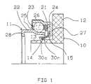
- the bearing 11 acts on the declutching device, constituted by way of example nonlimiting, by the ends of the fingers of a diaphragm which is part a clutch mechanism, also not shown.
- the support 10 is constituted, according to a known configuration, by a sleeve 13, the end of which carries the annular radial flange 12.
- the sleeve 13 is of cylindrical configuration and carries on its outer cylindrical surface, a circular rib 14, of locking of the assembly washer 15 of said support 10 and bearing 11.
- the bearing 11 has, in a manner known per se, an outer ring 21 and an inner ring 22, which carry the raceways of the bodies rollers 23, mounted in a cage 24.
- a seal 25 is integral of a sheet metal frame 26, crimped onto the outer ring 21.
- the outer ring 21 has a dropped edge 27, directed radially towards the axis of rotation of the bearing and mounted to bear on the flange 12 of the support 10.
- the ring 22 also carries in a known manner, a dropped edge 28, directed radially towards the axis of rotation of the bearing and adapted to act on the diaphragm of the clutch mechanism.
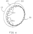
- Figure 4 shows the assembly washer 15. This has a radial support edge 29, intended to cooperate with the internal face "i" of the dropped edge 27 of the outer ring 21, facing the inner ring 22.
- the assembly washer 15 also has a termination constituted by a set of axial claws 30 distributed at the end opposite that of the radial support edge 29.
- a first series of elastic retaining claws 30r is intended to come in axial support on the circular rib 14 of the support 10.
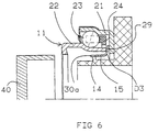
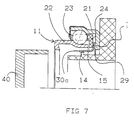
- a second series of actuating claws 30a is intended to form the support of a mounting tool 40 as shown in Figures 5 to 7.
- the ends of the claws 30r of the first series are elastic and exert a bending force in direction of the foot of the rib 14.
- the ends of the claws 30r are by elsewhere arranged along a first circumference D1 whose diameter is less than that of the circumference passing through the top of the rib 14.
- the ends of the claws 30a longitudinally alternating with the claws 30r along the periphery of the washer, extend axially and along a second circumference D2 whose diameter is greater than that of the circumference passing through the top of the rib 14.
- the claws 30a and 30r are directed in the opposite direction to the mounting direction of the washer and are of unequal lengths.
- the difference in claw length 30a and 30r is at least equal to the thickness of the rib 14 as is shown in Figures 5 to 7.
- This arrangement promotes contact of the washer 15 with the mounting tool. 40 and the temporary immobilization of the bearing 10 during the movement of the support 11.
- the end of the support 10 and the rib 14 are also move and radially deform all of the claws of deduction 30r.
- the claws 30r have a circular line D3 of folding together with the claws 30a and the diameter of this line of folding is substantially equal to the diameter of the circumference passing through the vertex of the rib 14. Such a configuration promotes the expansion of washer scratches during mounting of the bearing on its support.
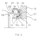
- FIG. 2 shows that the washer 15 can be immobilized as a result of the placing the end of the inner ring on the washer beforehand 22 of the bearing.
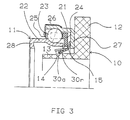
- FIG. 3 shows that the washer 15 can be immobilized as a result of the placing prior support on the washer of the cage 24 of the bearing 11.
Landscapes
- Engineering & Computer Science (AREA)
- General Engineering & Computer Science (AREA)
- Mechanical Engineering (AREA)
- Mechanical Operated Clutches (AREA)
Description
- La figure 1 est une demi-vue, en coupe axiale d'une butée assemblée, conforme à l'invention.
- La figure 2 est une demi-vue, en coupe axiale, d'une première variante de réalisation de la butée.
- La figure 3 est une demi-vue, en coupe axiale, d'une deuxième variante de réalisation de la butée.
- La figure 4 est une représentation perspective de la rondelle d'assemblage du roulement de butée sur son support.
- Les figures 5, 6, 7 sont des demi-vues en coupe axiale de la butée représentée aux figures 1, 2, 3, au cours de la phase d'assemblage du roulement de butée sur son support.
- un support de roulement 10 qui est destiné à être soumis à l'action d'un organe de manoeuvre, constitué à titre d'exemple non limitatif par une fourchette de commande, non représentée.
- un roulement de butée 11 directement en appui, à titre d'exemple contre un flasque radial 12 du support 10.
Claims (2)
- Butée de débrayage du type comportant un support de roulement (10) destiné à être soumis à l'action d'un organe de commande et un roulement de butée (11) assemblé et en appui axial contre ledit support de roulement (10) et qui sous l'action du support de roulement (10) agit sur le dispositif débrayeur d'un mécanisme d'embrayage, et dans laquelle une rondelle d'assemblage (15) desdits support (10) et roulement (11) possède une première série de griffes élastiques de retenue (30r) montées en appui axial sur une nervure circulaire (14) du support (10) et une deuxième série de griffes d'actionnement (30a) dirigées en sens inverse du sens de montage de la rondelle (15) dont les extrémités des griffes (30r) de la première série sont respectivement disposées le long d'une première circonférence (D1) dont le diamètre est inférieur à celui de la circonférence passant par le sommet de la nervure (14) tandisque les extrémités des griffes (30r) de la deuxième série sont disposées le long d'une deuxième circonférence (D2) dont le diamètre est supérieur à celui de la circonférence passant par le sommet de la nervure (14) et dans laquelle les griffes de retenue (30r) et les griffes d'actionnement (30a) sont de tailles inégales et leur différence de longueur est au moins égale à l'épaisseur de la nervure circulaire (14) du support (10), caractérisée par le fait que les griffes élastiques de retenue (30r) et d'actionnement (30a) sont longitudinalement alternées le long de la périphérie de la rondelle.
- Butée de débrayage selon la revendication 1, caractérisée par le fait qu'une ligne circulaire (D3) de pliage des griffes de retenue (30r) et d'actionnement (30a) de la rondelle d'assemblage (15) s'étend le long d'une circonférence de diamètre sensiblement égal au diamètre de la circonférence passant par le sommet de la nervure (14) du support.
Applications Claiming Priority (3)
| Application Number | Priority Date | Filing Date | Title |
|---|---|---|---|
| FR9702726 | 1997-03-07 | ||
| FR9702726A FR2760500B1 (fr) | 1997-03-07 | 1997-03-07 | Butee de debrayage |
| PCT/FR1998/000221 WO1998040637A1 (fr) | 1997-03-07 | 1998-02-06 | Butee de debrayage |
Publications (2)
| Publication Number | Publication Date |
|---|---|
| EP0965004A1 EP0965004A1 (fr) | 1999-12-22 |
| EP0965004B1 true EP0965004B1 (fr) | 2003-04-09 |
Family
ID=9504518
Family Applications (1)
| Application Number | Title | Priority Date | Filing Date |
|---|---|---|---|
| EP98906985A Expired - Lifetime EP0965004B1 (fr) | 1997-03-07 | 1998-02-06 | Butee de debrayage |
Country Status (5)
| Country | Link |
|---|---|
| EP (1) | EP0965004B1 (fr) |
| KR (1) | KR100516803B1 (fr) |
| DE (1) | DE69813192T2 (fr) |
| FR (1) | FR2760500B1 (fr) |
| WO (1) | WO1998040637A1 (fr) |
Families Citing this family (3)
| Publication number | Priority date | Publication date | Assignee | Title |
|---|---|---|---|---|
| DE102008054253A1 (de) * | 2008-10-31 | 2010-05-06 | Schaeffler Kg | Haltefederelement für ein Kupplungsbetätigungslager |
| FR2979678B1 (fr) * | 2011-09-06 | 2013-10-04 | Skf Ab | Butee d'embrayage-debrayage, de suspension ou de direction, procede de fabrication d'une telle butee et vehicule automobile equipe d'une telle butee |
| FR2979677B1 (fr) * | 2011-09-06 | 2014-04-25 | Skf Ab | Butee d'embrayage-debrayage de suspension ou de direction, procede de fabrication d'une telle butee et vehicule automobile equipe d'une telle butee |
Family Cites Families (4)
| Publication number | Priority date | Publication date | Assignee | Title |
|---|---|---|---|---|
| FR2607885B1 (fr) * | 1986-12-05 | 1991-01-25 | Valeo | Butee de debrayage a rondelle elastique bistable, notamment pour vehicule automobile |
| FR2611009B1 (fr) * | 1987-02-17 | 1989-05-19 | Valeo | Butee de debrayage, notamment pour vehicule automobile |
| FR2611244B1 (fr) * | 1987-02-20 | 1991-07-05 | Valeo | Butee de debrayage a piece elastique a action axiale, notamment pour vehicule automobile |
| FR2744776B1 (fr) * | 1996-02-08 | 1998-03-20 | Skf France | Butee d'embrayage a organe d'auto-alignement elastique |
-
1997
- 1997-03-07 FR FR9702726A patent/FR2760500B1/fr not_active Expired - Fee Related
-
1998
- 1998-02-06 EP EP98906985A patent/EP0965004B1/fr not_active Expired - Lifetime
- 1998-02-06 DE DE69813192T patent/DE69813192T2/de not_active Expired - Fee Related
- 1998-02-06 KR KR10-1999-7007950A patent/KR100516803B1/ko not_active Expired - Lifetime
- 1998-02-06 WO PCT/FR1998/000221 patent/WO1998040637A1/fr not_active Ceased
Also Published As
| Publication number | Publication date |
|---|---|
| FR2760500B1 (fr) | 1999-04-09 |
| FR2760500A1 (fr) | 1998-09-11 |
| DE69813192T2 (de) | 2003-12-18 |
| DE69813192D1 (de) | 2003-05-15 |
| KR20000075871A (ko) | 2000-12-26 |
| EP0965004A1 (fr) | 1999-12-22 |
| WO1998040637A1 (fr) | 1998-09-17 |
| KR100516803B1 (ko) | 2005-09-26 |
Similar Documents
| Publication | Publication Date | Title |
|---|---|---|
| EP1489327B1 (fr) | Butée de débrayage et procédé de montage | |
| EP1489325B1 (fr) | Butée de débrayage | |
| WO2002052163A1 (fr) | Butee pour embrayage, notamment de vehicule automobile | |
| FR2619880A1 (fr) | Butee de debrayage, notamment pour vehicules automobiles | |
| FR2465119A1 (fr) | Butee de debrayage | |
| FR2860847A1 (fr) | Dispositif de butee de debrayage | |
| EP3734129B1 (fr) | Dispositif de serrage comprenant un collier et un joint d'etancheite | |
| FR2544038A1 (fr) | Ensemble a butee de debrayage | |
| EP0220982B1 (fr) | Montage de butée de débrayage, notamment pour véhicule automobile | |
| FR2547002A1 (fr) | Butee de debrayage et outil de montage pour celle-ci | |
| FR2546999A1 (fr) | Mecanisme d'embrayage a piece rapportee sur le plateau de pression | |
| FR2607885A1 (fr) | Butee de debrayage a rondelle elastique bistable, notamment pour vehicule automobile | |
| FR2760500A1 (fr) | Butee de debrayage | |
| FR2459906A1 (fr) | Butee d'embrayage a auto-centrage | |
| WO2000057076A1 (fr) | Dispositif de montage d'un diaphragme sur un couvercle d'embrayage | |
| FR2898951A1 (fr) | Butee de debrayage auto-centreuse | |
| FR2465120A1 (fr) | Butee de debrayage | |
| EP0533537B1 (fr) | Butée de débrayage pour embrayage du type tiré, notamment pour véhicules automobiles | |
| FR2653194A1 (fr) | Ensemble d'accostage pour butee de debrayage, notamment pour vehicule automobile, et piece d'accostage d'un tel ensemble. | |
| EP0336843B1 (fr) | Tube-guide à étanchéité intégrée pour butée de débrayage de boite de vitesses de véhicule automobile | |
| FR2690959A1 (fr) | Friction d'embrayage, notamment pour véhicule automobile. | |
| FR2723995A1 (fr) | Butee de debrayage autocentreuse | |
| FR2658878A1 (fr) | Dispositif de connexion rapide entre deux portions d'une timonerie, notamment pour vehicule automobile. | |
| FR2652623A1 (fr) | Dispositif de butee d'embrayage a autocentrage du type tiree. | |
| FR2745051A1 (fr) | Montage de butee de debrayage, notamment pour vehicule automobile |
Legal Events
| Date | Code | Title | Description |
|---|---|---|---|
| PUAI | Public reference made under article 153(3) epc to a published international application that has entered the european phase |
Free format text: ORIGINAL CODE: 0009012 |
|
| 17P | Request for examination filed |
Effective date: 19990802 |
|
| AK | Designated contracting states |
Kind code of ref document: A1 Designated state(s): DE FR IT |
|
| 17Q | First examination report despatched |
Effective date: 20011221 |
|
| GRAH | Despatch of communication of intention to grant a patent |
Free format text: ORIGINAL CODE: EPIDOS IGRA |
|
| GRAH | Despatch of communication of intention to grant a patent |
Free format text: ORIGINAL CODE: EPIDOS IGRA |
|
| GRAA | (expected) grant |
Free format text: ORIGINAL CODE: 0009210 |
|
| AK | Designated contracting states |
Designated state(s): DE FR IT |
|
| PLBE | No opposition filed within time limit |
Free format text: ORIGINAL CODE: 0009261 |
|
| STAA | Information on the status of an ep patent application or granted ep patent |
Free format text: STATUS: NO OPPOSITION FILED WITHIN TIME LIMIT |
|
| 26N | No opposition filed |
Effective date: 20040112 |
|
| PGFP | Annual fee paid to national office [announced via postgrant information from national office to epo] |
Ref country code: DE Payment date: 20080219 Year of fee payment: 11 |
|
| PG25 | Lapsed in a contracting state [announced via postgrant information from national office to epo] |
Ref country code: DE Free format text: LAPSE BECAUSE OF NON-PAYMENT OF DUE FEES Effective date: 20090901 |
|
| REG | Reference to a national code |
Ref country code: FR Ref legal event code: PLFP Year of fee payment: 18 |
|
| REG | Reference to a national code |
Ref country code: FR Ref legal event code: PLFP Year of fee payment: 19 |
|
| REG | Reference to a national code |
Ref country code: FR Ref legal event code: PLFP Year of fee payment: 20 |
|
| PGFP | Annual fee paid to national office [announced via postgrant information from national office to epo] |
Ref country code: FR Payment date: 20170217 Year of fee payment: 20 |
|
| PGFP | Annual fee paid to national office [announced via postgrant information from national office to epo] |
Ref country code: IT Payment date: 20170221 Year of fee payment: 20 |