EP0964819B1 - Dismountable container - Google Patents
Dismountable container Download PDFInfo
- Publication number
- EP0964819B1 EP0964819B1 EP98960951A EP98960951A EP0964819B1 EP 0964819 B1 EP0964819 B1 EP 0964819B1 EP 98960951 A EP98960951 A EP 98960951A EP 98960951 A EP98960951 A EP 98960951A EP 0964819 B1 EP0964819 B1 EP 0964819B1
- Authority
- EP
- European Patent Office
- Prior art keywords
- box
- parts
- hinges
- side plates
- pairs
- Prior art date
- Legal status (The legal status is an assumption and is not a legal conclusion. Google has not performed a legal analysis and makes no representation as to the accuracy of the status listed.)
- Expired - Lifetime
Links
- 230000008878 coupling Effects 0.000 claims description 7
- 238000010168 coupling process Methods 0.000 claims description 7
- 238000005859 coupling reaction Methods 0.000 claims description 7
- 238000005260 corrosion Methods 0.000 claims description 3
- 238000006073 displacement reaction Methods 0.000 claims description 3
- 239000007769 metal material Substances 0.000 claims description 2
- 239000002184 metal Substances 0.000 description 8
- 239000011120 plywood Substances 0.000 description 8
- 239000000047 product Substances 0.000 description 6
- 239000002023 wood Substances 0.000 description 6
- 239000000463 material Substances 0.000 description 3
- 239000003795 chemical substances by application Substances 0.000 description 2
- 238000012423 maintenance Methods 0.000 description 2
- 230000010355 oscillation Effects 0.000 description 2
- XLYOFNOQVPJJNP-UHFFFAOYSA-N water Substances O XLYOFNOQVPJJNP-UHFFFAOYSA-N 0.000 description 2
- 230000006835 compression Effects 0.000 description 1
- 238000007906 compression Methods 0.000 description 1
- 230000007797 corrosion Effects 0.000 description 1
- 230000000694 effects Effects 0.000 description 1
- 238000002955 isolation Methods 0.000 description 1
- 238000004519 manufacturing process Methods 0.000 description 1
- 238000012856 packing Methods 0.000 description 1
- 239000012466 permeate Substances 0.000 description 1
- 239000013535 sea water Substances 0.000 description 1
- 238000004381 surface treatment Methods 0.000 description 1
Images


Classifications
-
- B—PERFORMING OPERATIONS; TRANSPORTING
- B65—CONVEYING; PACKING; STORING; HANDLING THIN OR FILAMENTARY MATERIAL
- B65D—CONTAINERS FOR STORAGE OR TRANSPORT OF ARTICLES OR MATERIALS, e.g. BAGS, BARRELS, BOTTLES, BOXES, CANS, CARTONS, CRATES, DRUMS, JARS, TANKS, HOPPERS, FORWARDING CONTAINERS; ACCESSORIES, CLOSURES, OR FITTINGS THEREFOR; PACKAGING ELEMENTS; PACKAGES
- B65D19/00—Pallets or like platforms, with or without side walls, for supporting loads to be lifted or lowered
- B65D19/02—Rigid pallets with side walls, e.g. box pallets
- B65D19/06—Rigid pallets with side walls, e.g. box pallets with bodies formed by uniting or interconnecting two or more components
- B65D19/14—Rigid pallets with side walls, e.g. box pallets with bodies formed by uniting or interconnecting two or more components made wholly or mainly of wood
- B65D19/16—Collapsible pallets
-
- B—PERFORMING OPERATIONS; TRANSPORTING
- B65—CONVEYING; PACKING; STORING; HANDLING THIN OR FILAMENTARY MATERIAL
- B65D—CONTAINERS FOR STORAGE OR TRANSPORT OF ARTICLES OR MATERIALS, e.g. BAGS, BARRELS, BOTTLES, BOXES, CANS, CARTONS, CRATES, DRUMS, JARS, TANKS, HOPPERS, FORWARDING CONTAINERS; ACCESSORIES, CLOSURES, OR FITTINGS THEREFOR; PACKAGING ELEMENTS; PACKAGES
- B65D2313/00—Connecting or fastening means
- B65D2313/02—Connecting or fastening means of hook-and-loop type
-
- B—PERFORMING OPERATIONS; TRANSPORTING
- B65—CONVEYING; PACKING; STORING; HANDLING THIN OR FILAMENTARY MATERIAL
- B65D—CONTAINERS FOR STORAGE OR TRANSPORT OF ARTICLES OR MATERIALS, e.g. BAGS, BARRELS, BOTTLES, BOXES, CANS, CARTONS, CRATES, DRUMS, JARS, TANKS, HOPPERS, FORWARDING CONTAINERS; ACCESSORIES, CLOSURES, OR FITTINGS THEREFOR; PACKAGING ELEMENTS; PACKAGES
- B65D2519/00—Pallets or like platforms, with or without side walls, for supporting loads to be lifted or lowered
- B65D2519/00004—Details relating to pallets
- B65D2519/00009—Materials
- B65D2519/00014—Materials for the load supporting surface
- B65D2519/00029—Wood
-
- B—PERFORMING OPERATIONS; TRANSPORTING
- B65—CONVEYING; PACKING; STORING; HANDLING THIN OR FILAMENTARY MATERIAL
- B65D—CONTAINERS FOR STORAGE OR TRANSPORT OF ARTICLES OR MATERIALS, e.g. BAGS, BARRELS, BOTTLES, BOXES, CANS, CARTONS, CRATES, DRUMS, JARS, TANKS, HOPPERS, FORWARDING CONTAINERS; ACCESSORIES, CLOSURES, OR FITTINGS THEREFOR; PACKAGING ELEMENTS; PACKAGES
- B65D2519/00—Pallets or like platforms, with or without side walls, for supporting loads to be lifted or lowered
- B65D2519/00004—Details relating to pallets
- B65D2519/00009—Materials
- B65D2519/00049—Materials for the base surface
- B65D2519/00064—Wood
-
- B—PERFORMING OPERATIONS; TRANSPORTING
- B65—CONVEYING; PACKING; STORING; HANDLING THIN OR FILAMENTARY MATERIAL
- B65D—CONTAINERS FOR STORAGE OR TRANSPORT OF ARTICLES OR MATERIALS, e.g. BAGS, BARRELS, BOTTLES, BOXES, CANS, CARTONS, CRATES, DRUMS, JARS, TANKS, HOPPERS, FORWARDING CONTAINERS; ACCESSORIES, CLOSURES, OR FITTINGS THEREFOR; PACKAGING ELEMENTS; PACKAGES
- B65D2519/00—Pallets or like platforms, with or without side walls, for supporting loads to be lifted or lowered
- B65D2519/00004—Details relating to pallets
- B65D2519/00009—Materials
- B65D2519/00084—Materials for the non-integral separating spacer
- B65D2519/00099—Wood
-
- B—PERFORMING OPERATIONS; TRANSPORTING
- B65—CONVEYING; PACKING; STORING; HANDLING THIN OR FILAMENTARY MATERIAL
- B65D—CONTAINERS FOR STORAGE OR TRANSPORT OF ARTICLES OR MATERIALS, e.g. BAGS, BARRELS, BOTTLES, BOXES, CANS, CARTONS, CRATES, DRUMS, JARS, TANKS, HOPPERS, FORWARDING CONTAINERS; ACCESSORIES, CLOSURES, OR FITTINGS THEREFOR; PACKAGING ELEMENTS; PACKAGES
- B65D2519/00—Pallets or like platforms, with or without side walls, for supporting loads to be lifted or lowered
- B65D2519/00004—Details relating to pallets
- B65D2519/00009—Materials
- B65D2519/00154—Materials for the side walls
- B65D2519/00169—Wood
-
- B—PERFORMING OPERATIONS; TRANSPORTING
- B65—CONVEYING; PACKING; STORING; HANDLING THIN OR FILAMENTARY MATERIAL
- B65D—CONTAINERS FOR STORAGE OR TRANSPORT OF ARTICLES OR MATERIALS, e.g. BAGS, BARRELS, BOTTLES, BOXES, CANS, CARTONS, CRATES, DRUMS, JARS, TANKS, HOPPERS, FORWARDING CONTAINERS; ACCESSORIES, CLOSURES, OR FITTINGS THEREFOR; PACKAGING ELEMENTS; PACKAGES
- B65D2519/00—Pallets or like platforms, with or without side walls, for supporting loads to be lifted or lowered
- B65D2519/00004—Details relating to pallets
- B65D2519/00009—Materials
- B65D2519/00189—Materials for the lid or cover
- B65D2519/00203—Wood
-
- B—PERFORMING OPERATIONS; TRANSPORTING
- B65—CONVEYING; PACKING; STORING; HANDLING THIN OR FILAMENTARY MATERIAL
- B65D—CONTAINERS FOR STORAGE OR TRANSPORT OF ARTICLES OR MATERIALS, e.g. BAGS, BARRELS, BOTTLES, BOXES, CANS, CARTONS, CRATES, DRUMS, JARS, TANKS, HOPPERS, FORWARDING CONTAINERS; ACCESSORIES, CLOSURES, OR FITTINGS THEREFOR; PACKAGING ELEMENTS; PACKAGES
- B65D2519/00—Pallets or like platforms, with or without side walls, for supporting loads to be lifted or lowered
- B65D2519/00004—Details relating to pallets
- B65D2519/00258—Overall construction
- B65D2519/00263—Overall construction of the pallet
- B65D2519/00273—Overall construction of the pallet made of more than one piece
-
- B—PERFORMING OPERATIONS; TRANSPORTING
- B65—CONVEYING; PACKING; STORING; HANDLING THIN OR FILAMENTARY MATERIAL
- B65D—CONTAINERS FOR STORAGE OR TRANSPORT OF ARTICLES OR MATERIALS, e.g. BAGS, BARRELS, BOTTLES, BOXES, CANS, CARTONS, CRATES, DRUMS, JARS, TANKS, HOPPERS, FORWARDING CONTAINERS; ACCESSORIES, CLOSURES, OR FITTINGS THEREFOR; PACKAGING ELEMENTS; PACKAGES
- B65D2519/00—Pallets or like platforms, with or without side walls, for supporting loads to be lifted or lowered
- B65D2519/00004—Details relating to pallets
- B65D2519/00258—Overall construction
- B65D2519/00283—Overall construction of the load supporting surface
- B65D2519/00288—Overall construction of the load supporting surface made of one piece
-
- B—PERFORMING OPERATIONS; TRANSPORTING
- B65—CONVEYING; PACKING; STORING; HANDLING THIN OR FILAMENTARY MATERIAL
- B65D—CONTAINERS FOR STORAGE OR TRANSPORT OF ARTICLES OR MATERIALS, e.g. BAGS, BARRELS, BOTTLES, BOXES, CANS, CARTONS, CRATES, DRUMS, JARS, TANKS, HOPPERS, FORWARDING CONTAINERS; ACCESSORIES, CLOSURES, OR FITTINGS THEREFOR; PACKAGING ELEMENTS; PACKAGES
- B65D2519/00—Pallets or like platforms, with or without side walls, for supporting loads to be lifted or lowered
- B65D2519/00004—Details relating to pallets
- B65D2519/00258—Overall construction
- B65D2519/00313—Overall construction of the base surface
- B65D2519/00323—Overall construction of the base surface made of more than one piece
-
- B—PERFORMING OPERATIONS; TRANSPORTING
- B65—CONVEYING; PACKING; STORING; HANDLING THIN OR FILAMENTARY MATERIAL
- B65D—CONTAINERS FOR STORAGE OR TRANSPORT OF ARTICLES OR MATERIALS, e.g. BAGS, BARRELS, BOTTLES, BOXES, CANS, CARTONS, CRATES, DRUMS, JARS, TANKS, HOPPERS, FORWARDING CONTAINERS; ACCESSORIES, CLOSURES, OR FITTINGS THEREFOR; PACKAGING ELEMENTS; PACKAGES
- B65D2519/00—Pallets or like platforms, with or without side walls, for supporting loads to be lifted or lowered
- B65D2519/00004—Details relating to pallets
- B65D2519/00258—Overall construction
- B65D2519/00313—Overall construction of the base surface
- B65D2519/00328—Overall construction of the base surface shape of the contact surface of the base
- B65D2519/00333—Overall construction of the base surface shape of the contact surface of the base contact surface having a stringer-like shape
-
- B—PERFORMING OPERATIONS; TRANSPORTING
- B65—CONVEYING; PACKING; STORING; HANDLING THIN OR FILAMENTARY MATERIAL
- B65D—CONTAINERS FOR STORAGE OR TRANSPORT OF ARTICLES OR MATERIALS, e.g. BAGS, BARRELS, BOTTLES, BOXES, CANS, CARTONS, CRATES, DRUMS, JARS, TANKS, HOPPERS, FORWARDING CONTAINERS; ACCESSORIES, CLOSURES, OR FITTINGS THEREFOR; PACKAGING ELEMENTS; PACKAGES
- B65D2519/00—Pallets or like platforms, with or without side walls, for supporting loads to be lifted or lowered
- B65D2519/00004—Details relating to pallets
- B65D2519/00258—Overall construction
- B65D2519/00368—Overall construction of the non-integral separating spacer
- B65D2519/00373—Overall construction of the non-integral separating spacer whereby at least one spacer is made of one piece
-
- B—PERFORMING OPERATIONS; TRANSPORTING
- B65—CONVEYING; PACKING; STORING; HANDLING THIN OR FILAMENTARY MATERIAL
- B65D—CONTAINERS FOR STORAGE OR TRANSPORT OF ARTICLES OR MATERIALS, e.g. BAGS, BARRELS, BOTTLES, BOXES, CANS, CARTONS, CRATES, DRUMS, JARS, TANKS, HOPPERS, FORWARDING CONTAINERS; ACCESSORIES, CLOSURES, OR FITTINGS THEREFOR; PACKAGING ELEMENTS; PACKAGES
- B65D2519/00—Pallets or like platforms, with or without side walls, for supporting loads to be lifted or lowered
- B65D2519/00004—Details relating to pallets
- B65D2519/00258—Overall construction
- B65D2519/00492—Overall construction of the side walls
- B65D2519/00497—Overall construction of the side walls whereby at least one side wall is made of one piece
-
- B—PERFORMING OPERATIONS; TRANSPORTING
- B65—CONVEYING; PACKING; STORING; HANDLING THIN OR FILAMENTARY MATERIAL
- B65D—CONTAINERS FOR STORAGE OR TRANSPORT OF ARTICLES OR MATERIALS, e.g. BAGS, BARRELS, BOTTLES, BOXES, CANS, CARTONS, CRATES, DRUMS, JARS, TANKS, HOPPERS, FORWARDING CONTAINERS; ACCESSORIES, CLOSURES, OR FITTINGS THEREFOR; PACKAGING ELEMENTS; PACKAGES
- B65D2519/00—Pallets or like platforms, with or without side walls, for supporting loads to be lifted or lowered
- B65D2519/00004—Details relating to pallets
- B65D2519/00547—Connections
- B65D2519/00577—Connections structures connecting side walls, including corner posts, to each other
- B65D2519/00582—Connections structures connecting side walls, including corner posts, to each other structures intended to be disassembled, i.e. collapsible or dismountable
- B65D2519/00587—Connections structures connecting side walls, including corner posts, to each other structures intended to be disassembled, i.e. collapsible or dismountable side walls directly connected to each other
- B65D2519/00592—Connections structures connecting side walls, including corner posts, to each other structures intended to be disassembled, i.e. collapsible or dismountable side walls directly connected to each other by means of hinges
- B65D2519/00601—Connections structures connecting side walls, including corner posts, to each other structures intended to be disassembled, i.e. collapsible or dismountable side walls directly connected to each other by means of hinges separately formed
-
- B—PERFORMING OPERATIONS; TRANSPORTING
- B65—CONVEYING; PACKING; STORING; HANDLING THIN OR FILAMENTARY MATERIAL
- B65D—CONTAINERS FOR STORAGE OR TRANSPORT OF ARTICLES OR MATERIALS, e.g. BAGS, BARRELS, BOTTLES, BOXES, CANS, CARTONS, CRATES, DRUMS, JARS, TANKS, HOPPERS, FORWARDING CONTAINERS; ACCESSORIES, CLOSURES, OR FITTINGS THEREFOR; PACKAGING ELEMENTS; PACKAGES
- B65D2519/00—Pallets or like platforms, with or without side walls, for supporting loads to be lifted or lowered
- B65D2519/00004—Details relating to pallets
- B65D2519/00547—Connections
- B65D2519/00636—Connections structures connecting side walls to the pallet
- B65D2519/00641—Structures intended to be disassembled
- B65D2519/00661—Structures intended to be disassembled side walls maintained connected to pallet by means of auxiliary locking elements, e.g. spring loaded locking pins
-
- B—PERFORMING OPERATIONS; TRANSPORTING
- B65—CONVEYING; PACKING; STORING; HANDLING THIN OR FILAMENTARY MATERIAL
- B65D—CONTAINERS FOR STORAGE OR TRANSPORT OF ARTICLES OR MATERIALS, e.g. BAGS, BARRELS, BOTTLES, BOXES, CANS, CARTONS, CRATES, DRUMS, JARS, TANKS, HOPPERS, FORWARDING CONTAINERS; ACCESSORIES, CLOSURES, OR FITTINGS THEREFOR; PACKAGING ELEMENTS; PACKAGES
- B65D2519/00—Pallets or like platforms, with or without side walls, for supporting loads to be lifted or lowered
- B65D2519/00004—Details relating to pallets
- B65D2519/00547—Connections
- B65D2519/00706—Connections structures connecting the lid or cover to the side walls or corner posts
- B65D2519/00711—Connections structures connecting the lid or cover to the side walls or corner posts removable lid or covers
Landscapes
- Engineering & Computer Science (AREA)
- Life Sciences & Earth Sciences (AREA)
- Wood Science & Technology (AREA)
- Mechanical Engineering (AREA)
- Rigid Containers With Two Or More Constituent Elements (AREA)
- Pallets (AREA)
- Details Of Rigid Or Semi-Rigid Containers (AREA)
- Packaging Of Machine Parts And Wound Products (AREA)
Description
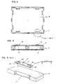
- Figure 1 is a perspective view of one embodiment of the box in accordance with the invention, in a fully closed position;
- Figure 2 is a perspective view of the same box but showing its cover raised;
- Figure 3 is an exploded perspective view of the box shown in Figure 1;
- Figure 4 is a bottom plan view of the box shown in Figure 1,
- Figure 5 is a front view of the bottom of the box shown in Figure 1;
- Figure 6 is a detailed view of the attachment of a metallic part of the box shown in Figure 1;
- Figure 7 is a plan view of one side of the box shown in Figure 1 and details of the metallic parts;
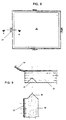
- Figure 8 is a plan view of the cover of the box shown in Figure 1;
- Figure 9 is a view along cut line X-X shown in Figure 8;
- Figure 10 is a partially exploded perspective view of the interior of the box of the present invention as illustrated in Figure 1;
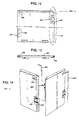
- Figure 11 is a perspective view of a preferred embodiment of the box according to the invention, in a closed position;
- Figure 12 is a front view of a preferred embodiment of one of the side plates;
- Figure 13 is a top view of the side plate shown in Figure 12;
- Figure 14 is a perspective exploded view of the connection of two side plates of the preferred embodiment according to Figure 11;
- Figure 15 is a perspective view of preferred embodiment of the metallic locking part;
- Figure 16 is a front view of a preferred embodiment of the lower metallic locking part of the side plates; and
- Figure 17 is a profile view of the metallic locking part a shown in Figure 16.
- outer hinges that allow an overall view of the elements for assembling and disassembling the box;
- outer hinges that allow the operator who assembles and disassembles the box to fully view the coupling/uncoupling operation of the locking rods when the boxes are stacked in great heights;
- hinges having alternating inner/outer attachment above/below the side plate median line which provide more stability to the attachment of side plates to the box and at the same time cut to half the number of hinges;
- lower metallic locking part of side plates stamped as a single body, what provides more mechanical strength thereto; and
- upper recess in the side plate, what makes possible to attain a perfect fitting of the ends of the hinge locking rod and avoids vertical displacements of said rod.
Claims (9)
- A box for transporting and storing of products, said box being especially adjusted for the transport of pieces and automotive vehicle parts and also able to be disassembled and restored to its original shape, comprising a pallet type bottom plate (10), side plates (20) and upper cover (30), said side plates (20) being coupled to bottom plate (10) by means of pairs of parts (27; 28) in the lower portion that cooperate with the respective pairs of parts (12'; 13') of said bottom plate (10) and to cover (30) by means of latches (20'; 30'), said pairs of parts (27; 28) of the side plates (20) facing the interior of said box with no portion thereof projected in its outer surface,
said side plates (20) being coupled together by means of pairs of side hinges (24; 25), wherein each pair of hinges (24; 25) of a side plate (20) fits into the respective pair of hinges (24'; 25') of an adjacent side plate (20),
all said pairs of side hinges (24; 25) and said pairs of parts (12'; 13') of bottom plate (10) facing the interior of said box with no portion thereof projected in its outer surface,
characterized in that the side hinges (24; 25) are kept joined by a rod (40),
in that said pairs of parts (12'; 13') of bottom plate (10) are provided with respective locking pins (12"; 13") for cooperating with the respective pairs of parts (27; 28) of the side plates (20), thus forming a lower locking latch in the side plates (20),
in that said side plates (20) are provided with a wedge-shaped longitudinal protuberance (26) in its upper end portion for coupling to respective recesses (31) provided in the inner face of cover (30). - The box according to claim 1, wherein said rod (40) is provided with one L-shaped folded end.
- The box according to claim 1 or 2, wherein said hinges (24 ; 25), said parts (27; 28; 12'; 13') and said rod (40) are all made of anti-corrosion metallic material which is otherwise submitted to anticorrosive treatment.
- The box according to any one of the preceding claims, wherein said side plates (20) are provided with longitudinal side recesses (22 ; 23), in the boundaries of which are pairs of hinges (24 ; 25).
- The box according to any one of the preceding claims, wherein said side plates (20) have a straight base (21) to rest on an insert (11) of bottom plate (10).
- The box according to claim 1, wherein said bottom plate (10) has a surface area lower than that of said insert (11) and is also provided with recesses (12 ; 13) in its ends, in the boundaries of which said pairs of parts (12'; 13') is attached to.
- The box according to claim 1, wherein the parts (27; 28) have a "U" profile wherein a parallel surface (27c) is wider than the other one (27d).
- The box according to any one of the preceding claims, wherein the hinges (24; 25) are positioned in the boundaries of recesses (22 ; 23) with their joints facing said recesses.
- A box for transporting and storing different products, as defined in any of the preceding claims, comprising an outer side closure comprised of (i) a side plate structure (200) and (ii) a lower metallic locking structure (120) of side plates (200),
characterized in that said side plate structure (200) has recesses (210; 220) along its side ends and is disposed in an alternating inner/outer fashion, over which respective joints (230'; 240') of hinges (230; 240) are disposed, which hinges are attached to the same plate (200) in an alternating inner/outer fashion above/below horizontal median line X of said plate (200) in the upper portion of which there is a horizontal recess (250) sufficient for a upper L-shaped end of rod (400) to fit and be locked therein against vertical displacement and,
in that said lower metallic locking structure (120) is provided with an arc-shaped notch (120') stamped in its own surface.
Applications Claiming Priority (3)
| Application Number | Priority Date | Filing Date | Title |
|---|---|---|---|
| BR9706337-1A BR9706337C2 (en) | 1997-12-30 | 1997-12-30 | Optimized box for transportation and storage of various products. |
| BR9706337 | 1998-09-21 | ||
| PCT/BR1998/000110 WO1999035043A1 (en) | 1997-12-30 | 1998-12-22 | Dismountable container |
Publications (2)
| Publication Number | Publication Date |
|---|---|
| EP0964819A1 EP0964819A1 (en) | 1999-12-22 |
| EP0964819B1 true EP0964819B1 (en) | 2002-09-25 |
Family
ID=4068711
Family Applications (1)
| Application Number | Title | Priority Date | Filing Date |
|---|---|---|---|
| EP98960951A Expired - Lifetime EP0964819B1 (en) | 1997-12-30 | 1998-12-22 | Dismountable container |
Country Status (10)
| Country | Link |
|---|---|
| US (1) | US6216899B1 (en) |
| EP (1) | EP0964819B1 (en) |
| JP (1) | JP2000142694A (en) |
| CN (1) | CN1090583C (en) |
| AR (1) | AR015208A1 (en) |
| BR (1) | BR9706337C2 (en) |
| CA (1) | CA2282646A1 (en) |
| DE (1) | DE69808253D1 (en) |
| WO (1) | WO1999035043A1 (en) |
| ZA (1) | ZA9811951B (en) |
Cited By (1)
| Publication number | Priority date | Publication date | Assignee | Title |
|---|---|---|---|---|
| RU174939U1 (en) * | 2017-07-20 | 2017-11-13 | Общество с ограниченной ответственностью "Уральские локомотивы" | ELECTROTECHNICAL BOX |
Families Citing this family (59)
| Publication number | Priority date | Publication date | Assignee | Title |
|---|---|---|---|---|
| US6409647B1 (en) * | 2000-06-27 | 2002-06-25 | Earl D. Bevins | Device for assembling collapsible containers |
| US6631821B2 (en) * | 2000-10-31 | 2003-10-14 | Peter N. Vourganas | Reinforced double-wall knock-down bin |
| US6581769B2 (en) * | 2000-12-04 | 2003-06-24 | Robert Nist | Corrugated shipping container with self-hinged door |
| US6811048B2 (en) * | 2002-02-12 | 2004-11-02 | David M. K. Lau | Fold-up storage container |
| US6601723B1 (en) | 2002-04-30 | 2003-08-05 | Lamont Limited | Method and system for providing an easily assembled rigid-walled wicker hamper |
| FR2848988B1 (en) * | 2002-12-20 | 2005-01-28 | Renault Sa | DEVICE FOR ASSEMBLING A MEANS OF CONDITIONING |
| FR2850547B1 (en) * | 2003-02-04 | 2006-06-23 | Oreal | HOUSING COMPRISING AN ARTICULATION HAVING A BUCKLE ELEMENT AND A HOLE ELEMENT |
| US7175010B1 (en) * | 2004-02-17 | 2007-02-13 | Michelle Yvette Miner | Collapsible luggage |
| FR2868043B1 (en) * | 2004-03-29 | 2006-08-11 | Larousse Emballage Sa | ATTACHE BETWEEN A BELT IN SEMI-RIGID MATERIAL AND A PLANAR SUPPORT FOR FORMING A BODY THE FUND THUS FORMED |
| US7156249B2 (en) | 2004-04-09 | 2007-01-02 | The United States Of America As Represented By The Secretary Of The Navy | Container, and related methods |
| JP3675809B1 (en) * | 2004-08-31 | 2005-07-27 | 渡邊 隆久 | Container coupler and prefabricated container using the same |
| US20060186118A1 (en) * | 2005-02-24 | 2006-08-24 | Stojak Kenneth R | Reusable container |
| US20060273083A1 (en) * | 2005-06-06 | 2006-12-07 | Avraham Lev | Modular bin system and bin |
| SE528875C2 (en) * | 2005-07-11 | 2007-03-06 | Crossborder Technologies Ab | Pallet |
| US7874435B2 (en) * | 2005-08-23 | 2011-01-25 | Integris Rentals, L.L.C. | Pipeline pig storage rack apparatus |
| FR2903669B3 (en) * | 2006-07-13 | 2008-06-20 | Claude Guyotjeannin | REMOVABLE. |
| CN200985180Y (en) * | 2006-09-01 | 2007-12-05 | 毛昭宁 | Foldable container |
| US20080083765A1 (en) * | 2006-10-05 | 2008-04-10 | Robert Lee Landsinger | Portable container for assembly at point of use |
| US20090057272A1 (en) * | 2007-08-28 | 2009-03-05 | Modgil Arun | Shipping case and connecting device for use with case |
| US20090242553A1 (en) * | 2008-03-28 | 2009-10-01 | Sheldon Mickelson | Construction waste removal container |
| KR200448969Y1 (en) | 2008-05-02 | 2010-06-09 | 한국컨테이너풀 주식회사 | A box |
| US9878819B2 (en) * | 2009-12-28 | 2018-01-30 | Packaging Engineering, Llc | Reusable container with interlocking members and method of using same |
| CN102259731A (en) * | 2010-05-26 | 2011-11-30 | 信义汽车玻璃(深圳)有限公司 | Wooden box for packaging automobile glasses |
| CL2010000779A1 (en) * | 2010-07-22 | 2011-02-18 | Compania Patentes Del Pacifico Spa | Self-assembling container container, comprising the following main structural elements, a bottom, two longitudinal or larger sides and two transverse or smaller sides, grooves and flexible harpoons resistant to traction; and method of manufacturing structural elements of a self-assembling container container. |
| US8950613B2 (en) * | 2011-02-16 | 2015-02-10 | Orbis Corporation | Bulk bin container with removable side wall |
| CA2782956C (en) * | 2011-06-29 | 2019-08-13 | Rehrig Pacific Company | Crate with retractable wall |
| US20130015184A1 (en) * | 2011-07-11 | 2013-01-17 | Marietta Lake | Reusable cover with integrated fasteners for transporting goods on an industrial shipping rack |
| US8708178B2 (en) * | 2011-07-26 | 2014-04-29 | Diversified Fixtures, Inc. | Container system and method |
| EP2669207B1 (en) * | 2012-05-29 | 2016-07-20 | Nefab Ab | A system for creating a container and corresponding container |
| CN102795379B (en) * | 2012-07-10 | 2015-07-08 | 无锡市前程包装工程有限公司 | Removable modular packing box with extensible dimension |
| US8915397B2 (en) | 2012-11-01 | 2014-12-23 | Orbis Corporation | Bulk container with center support between drop door and side wall |
| CN103010556B (en) * | 2012-12-12 | 2015-03-18 | 无锡市前程包装工程有限公司 | Foldable and detachable type wood pallet box |
| CN103057792A (en) * | 2013-01-18 | 2013-04-24 | 嘉兴市正基电子有限公司 | Boarding box and manufacturing method thereof |
| US8813985B2 (en) * | 2013-01-30 | 2014-08-26 | Diversified Fixtures, Inc. | Container system and method |
| CN103395544A (en) * | 2013-08-23 | 2013-11-20 | 常熟市东方新型包装材料有限公司 | Multifunctional log pallet |
| CN103523384A (en) * | 2013-10-29 | 2014-01-22 | 高佳太阳能股份有限公司 | Transport packaging box for silicon wafers |
| US9708097B2 (en) | 2013-11-15 | 2017-07-18 | Orbis Corporation | Bulk bin with integrated shock absorber |
| US9487326B2 (en) | 2013-11-26 | 2016-11-08 | Orbis Corporation | Bulk bin with panel to panel interlock features |
| CN103723331A (en) * | 2013-12-10 | 2014-04-16 | 昆山市华奎机械电子有限公司 | Containing box of stamped parts |
| US9863174B2 (en) | 2014-06-20 | 2018-01-09 | Orbis Corporation | Hinge rod trap for a collapsible bin |
| CA3194864A1 (en) | 2015-07-08 | 2017-01-12 | Divert, Inc. | System for tracking waste or recyclable material |
| CN106428899B (en) * | 2015-08-07 | 2019-08-06 | 姚本海 | A kind of bamboo Anti-sliding tray and its manufacturing method |
| WO2017112985A1 (en) * | 2015-12-30 | 2017-07-06 | Costa De Almeida Gustavo | Structural arrangement for use in assemblable packaging |
| CN105644886B (en) * | 2016-03-17 | 2018-01-16 | 重庆大学 | A kind of dismountable casing |
| US20170297500A1 (en) * | 2016-04-14 | 2017-10-19 | Guadalupe Arellanes | Portable Golf Bag Carrying and Transporting Device |
| CN106428891A (en) * | 2016-12-16 | 2017-02-22 | 丁静亚 | Environment-friendly plastic boarding box with locking function |
| US10689155B2 (en) | 2017-01-02 | 2020-06-23 | Lyno Lewis Sullivan | Modular storage container system |
| IT201700012289A1 (en) * | 2017-02-06 | 2018-08-06 | Valeriano Raineri | LOCKING DEVICE FOR CASES. |
| US10532853B2 (en) * | 2018-01-05 | 2020-01-14 | Easy Gardener Products, Inc. | Product display container |
| JP7069790B2 (en) * | 2018-02-14 | 2022-05-18 | 株式会社リコー | Fixing device |
| AU2019255805B2 (en) * | 2018-04-20 | 2024-01-18 | Marco Prieschl | Storage apparatus |
| US11299862B1 (en) * | 2018-08-29 | 2022-04-12 | Studio5051, Llc | Portable street planter |
| CN109118973A (en) * | 2018-09-28 | 2019-01-01 | 深圳市光祥科技股份有限公司 | LED display cabinet transport vehicle |
| US11869389B2 (en) | 2018-12-14 | 2024-01-09 | Tradeshow Fairy Llc | Tradeshow display crate |
| US11382439B1 (en) * | 2019-07-12 | 2022-07-12 | Walgreen Co. | Locking case system and method for cosmetic products |
| EP4031861A4 (en) | 2019-09-18 | 2023-07-19 | Divert, Inc. | Systems and methods for tracking product environment throughout a supply chain |
| US20230052384A1 (en) * | 2019-10-15 | 2023-02-16 | Richard ANECK-HAHN | A modular produce crate |
| FR3105188B1 (en) * | 2019-12-18 | 2021-12-10 | Julien Pruvost | Construction panel, associated kit and associated modular object |
| CN114955159B (en) * | 2022-06-07 | 2023-07-18 | 合肥祥恒包装有限公司 | Environment-friendly packing box capable of being packaged rapidly |
Family Cites Families (24)
| Publication number | Priority date | Publication date | Assignee | Title |
|---|---|---|---|---|
| US753889A (en) * | 1903-06-24 | 1904-03-08 | Hugh L Jones | Box-fastener. |
| US1231977A (en) * | 1915-10-12 | 1917-07-03 | H C Faber & Son Company | Knockdown receptacle. |
| US1209027A (en) * | 1916-01-11 | 1916-12-19 | Paul R Quade | Knockdown shipping-box. |
| GB303050A (en) | 1927-09-27 | 1928-12-27 | Arthur Kitchener Walter | Improvements in collapsible boxes |
| US1894022A (en) * | 1929-08-14 | 1933-01-10 | Bell Telephone Labor Inc | Container |
| US2650737A (en) * | 1949-12-29 | 1953-09-01 | American Car & Foundry Co | Knockdown shipping container |
| US3401814A (en) * | 1967-03-07 | 1968-09-17 | Collapsible Container Corp | Collapsible shipping container |
| US3451578A (en) | 1967-06-01 | 1969-06-24 | John D Edmundson | Collapsible container |
| US4186841A (en) * | 1977-09-29 | 1980-02-05 | Federal Reserve Bank Of Boston | Pallet |
| DE2836379C3 (en) * | 1978-08-19 | 1981-11-26 | Langer, geb. Layher, Ruth, 7129 Güglingen | palette |
| BR6200841U (en) | 1982-06-16 | 1982-12-28 | Edda Dorothy Bragazza Vicari | ASSEMBLY BOXES FOR EXPORT PRODUCT PACKAGES |
| CA1225941A (en) * | 1985-01-22 | 1987-08-25 | Larry R. Hughes | Collapsible shipping container |
| FR2624831B1 (en) | 1987-12-16 | 1990-04-13 | Mussy Emballages Sa | FOLDABLE COMPOSITE PACKAGING BOX |
| US5161709A (en) * | 1989-01-30 | 1992-11-10 | World Container Corporation | Hinged collapsible container |
| FR2661656B1 (en) | 1990-05-03 | 1994-05-13 | Benoit Arnaud | CASH PALLET. |
| GB2257453B (en) | 1991-01-28 | 1994-05-11 | Lydney Holdings Limited | A clip for holding together panels of a box-like container |
| DE9203216U1 (en) | 1992-03-10 | 1992-05-27 | Clip-Lok International Ltd., Staines, Middlesex, Gb | |
| DE9308892U1 (en) * | 1993-04-16 | 1993-09-02 | Christoph Michael | Packaging container |
| MY111213A (en) | 1993-04-29 | 1999-09-30 | Clip Lok International Ltd | Transport container |
| GB9323815D0 (en) | 1993-11-19 | 1994-01-05 | Clip Lok Int Ltd | A container clamping device |
| US5669507A (en) * | 1996-04-17 | 1997-09-23 | Pruitt, Jr.; John F. | Pallet box container |
| US5638973A (en) * | 1996-05-09 | 1997-06-17 | Western Poly Corporation | Storage container with interlocking corner members |
| DE29704617U1 (en) | 1997-03-13 | 1997-06-26 | Oeco Team Gmbh Transport Und L | Foldable container |
| US6019226A (en) * | 1998-08-24 | 2000-02-01 | Ace Packaging Systems, Inc. | Demountable palletized container |
-
1997
- 1997-12-30 BR BR9706337-1A patent/BR9706337C2/en not_active IP Right Cessation
-
1998
- 1998-12-22 CA CA002282646A patent/CA2282646A1/en not_active Abandoned
- 1998-12-22 EP EP98960951A patent/EP0964819B1/en not_active Expired - Lifetime
- 1998-12-22 CN CN98802965A patent/CN1090583C/en not_active Expired - Fee Related
- 1998-12-22 US US09/380,388 patent/US6216899B1/en not_active Expired - Fee Related
- 1998-12-22 WO PCT/BR1998/000110 patent/WO1999035043A1/en active IP Right Grant
- 1998-12-22 DE DE69808253T patent/DE69808253D1/en not_active Expired - Lifetime
- 1998-12-28 AR ARP980106694A patent/AR015208A1/en not_active Application Discontinuation
- 1998-12-30 ZA ZA9811951A patent/ZA9811951B/en unknown
-
1999
- 1999-09-21 JP JP11305922A patent/JP2000142694A/en active Pending
Cited By (1)
| Publication number | Priority date | Publication date | Assignee | Title |
|---|---|---|---|---|
| RU174939U1 (en) * | 2017-07-20 | 2017-11-13 | Общество с ограниченной ответственностью "Уральские локомотивы" | ELECTROTECHNICAL BOX |
Also Published As
| Publication number | Publication date |
|---|---|
| BR9706337A (en) | 2000-02-29 |
| WO1999035043A1 (en) | 1999-07-15 |
| ZA9811951B (en) | 1999-08-17 |
| BR9706337C1 (en) | 2000-03-21 |
| AR015208A1 (en) | 2001-04-18 |
| US6216899B1 (en) | 2001-04-17 |
| JP2000142694A (en) | 2000-05-23 |
| CN1249722A (en) | 2000-04-05 |
| DE69808253D1 (en) | 2002-10-31 |
| CA2282646A1 (en) | 1999-07-15 |
| EP0964819A1 (en) | 1999-12-22 |
| CN1090583C (en) | 2002-09-11 |
| BR9706337C2 (en) | 2000-03-21 |
Similar Documents
| Publication | Publication Date | Title |
|---|---|---|
| EP0964819B1 (en) | Dismountable container | |
| US4261470A (en) | Collapsible rack | |
| US5950546A (en) | Double deck fold-up pallet | |
| EP0029750B1 (en) | Folding containers | |
| EP0708732B1 (en) | Improvements in or relating to freight containers | |
| EP2593375B1 (en) | Flex assembly of pallet base and deck | |
| US3456830A (en) | Freight containers | |
| SK279763B6 (en) | Collapsible cargo cabinet or container | |
| GB2145397A (en) | Freight container for flowable materials | |
| MX2013005098A (en) | Auxiliary transport unit and method for use thereof. | |
| US7011223B1 (en) | Foldable end frame container | |
| US5076454A (en) | Knock-down shipping and storage container | |
| CA2028858C (en) | Two-part crate of plastic or the like | |
| SK280846B6 (en) | Transport container | |
| US4948005A (en) | Knock-down shipping and storage container | |
| US20030233963A1 (en) | Central pallet connector or post for use with grabber arms of a forklift | |
| US7387215B1 (en) | Foldable end frame container | |
| MXPA99007960A (en) | Dismountable container | |
| US5813555A (en) | Wing-end cleated crate | |
| KR20080006142U (en) | Fabricated Palette | |
| KR100433289B1 (en) | Pallet for loading goods | |
| JP3875803B2 (en) | Assembled container | |
| CN104870326A (en) | Corner fitting for box-like structures on transport pallets | |
| JP3978352B2 (en) | palette | |
| KR200222629Y1 (en) | assembly type packing box |
Legal Events
| Date | Code | Title | Description |
|---|---|---|---|
| PUAI | Public reference made under article 153(3) epc to a published international application that has entered the european phase |
Free format text: ORIGINAL CODE: 0009012 |
|
| AK | Designated contracting states |
Kind code of ref document: A1 Designated state(s): DE ES FR IT PT SE |
|
| 17P | Request for examination filed |
Effective date: 20000110 |
|
| 17Q | First examination report despatched |
Effective date: 20000905 |
|
| GRAG | Despatch of communication of intention to grant |
Free format text: ORIGINAL CODE: EPIDOS AGRA |
|
| GRAG | Despatch of communication of intention to grant |
Free format text: ORIGINAL CODE: EPIDOS AGRA |
|
| GRAH | Despatch of communication of intention to grant a patent |
Free format text: ORIGINAL CODE: EPIDOS IGRA |
|
| GRAH | Despatch of communication of intention to grant a patent |
Free format text: ORIGINAL CODE: EPIDOS IGRA |
|
| GRAA | (expected) grant |
Free format text: ORIGINAL CODE: 0009210 |
|
| AK | Designated contracting states |
Kind code of ref document: B1 Designated state(s): DE ES FR IT PT SE |
|
| REF | Corresponds to: |
Ref document number: 69808253 Country of ref document: DE Date of ref document: 20021031 |
|
| PG25 | Lapsed in a contracting state [announced via postgrant information from national office to epo] |
Ref country code: SE Free format text: LAPSE BECAUSE OF FAILURE TO SUBMIT A TRANSLATION OF THE DESCRIPTION OR TO PAY THE FEE WITHIN THE PRESCRIBED TIME-LIMIT Effective date: 20021225 |
|
| PG25 | Lapsed in a contracting state [announced via postgrant information from national office to epo] |
Ref country code: PT Free format text: LAPSE BECAUSE OF FAILURE TO SUBMIT A TRANSLATION OF THE DESCRIPTION OR TO PAY THE FEE WITHIN THE PRESCRIBED TIME-LIMIT Effective date: 20021226 |
|
| PG25 | Lapsed in a contracting state [announced via postgrant information from national office to epo] |
Ref country code: DE Free format text: LAPSE BECAUSE OF FAILURE TO SUBMIT A TRANSLATION OF THE DESCRIPTION OR TO PAY THE FEE WITHIN THE PRESCRIBED TIME-LIMIT Effective date: 20021228 |
|
| PG25 | Lapsed in a contracting state [announced via postgrant information from national office to epo] |
Ref country code: ES Free format text: LAPSE BECAUSE OF FAILURE TO SUBMIT A TRANSLATION OF THE DESCRIPTION OR TO PAY THE FEE WITHIN THE PRESCRIBED TIME-LIMIT Effective date: 20030328 |
|
| ET | Fr: translation filed | ||
| PLBE | No opposition filed within time limit |
Free format text: ORIGINAL CODE: 0009261 |
|
| STAA | Information on the status of an ep patent application or granted ep patent |
Free format text: STATUS: NO OPPOSITION FILED WITHIN TIME LIMIT |
|
| 26N | No opposition filed |
Effective date: 20030626 |
|
| PGFP | Annual fee paid to national office [announced via postgrant information from national office to epo] |
Ref country code: FR Payment date: 20031204 Year of fee payment: 6 |
|
| PG25 | Lapsed in a contracting state [announced via postgrant information from national office to epo] |
Ref country code: FR Free format text: LAPSE BECAUSE OF NON-PAYMENT OF DUE FEES Effective date: 20050831 |
|
| REG | Reference to a national code |
Ref country code: FR Ref legal event code: ST |
|
| PG25 | Lapsed in a contracting state [announced via postgrant information from national office to epo] |
Ref country code: IT Free format text: LAPSE BECAUSE OF NON-PAYMENT OF DUE FEES Effective date: 20051222 |