EP0964133A1 - Boítier pour transmetteur - Google Patents
Boítier pour transmetteur Download PDFInfo
- Publication number
- EP0964133A1 EP0964133A1 EP99110095A EP99110095A EP0964133A1 EP 0964133 A1 EP0964133 A1 EP 0964133A1 EP 99110095 A EP99110095 A EP 99110095A EP 99110095 A EP99110095 A EP 99110095A EP 0964133 A1 EP0964133 A1 EP 0964133A1
- Authority
- EP
- European Patent Office
- Prior art keywords
- transmitter
- housing
- boring machine
- ram boring
- ram
- Prior art date
- Legal status (The legal status is an assumption and is not a legal conclusion. Google has not performed a legal analysis and makes no representation as to the accuracy of the status listed.)
- Granted
Links
- 230000005540 biological transmission Effects 0.000 claims abstract description 8
- 229920003023 plastic Polymers 0.000 claims abstract description 8
- 239000004033 plastic Substances 0.000 claims abstract description 8
- 238000013016 damping Methods 0.000 claims abstract description 7
- 238000006073 displacement reaction Methods 0.000 claims description 11
- 150000001875 compounds Chemical class 0.000 claims description 2
- 230000008878 coupling Effects 0.000 claims description 2
- 238000010168 coupling process Methods 0.000 claims description 2
- 238000005859 coupling reaction Methods 0.000 claims description 2
- 238000000034 method Methods 0.000 claims 1
- 230000004308 accommodation Effects 0.000 abstract 1
- 238000005553 drilling Methods 0.000 description 5
- 230000001133 acceleration Effects 0.000 description 1
- 238000010276 construction Methods 0.000 description 1
- 230000002950 deficient Effects 0.000 description 1
- 238000005259 measurement Methods 0.000 description 1
- 230000002093 peripheral effect Effects 0.000 description 1
- 238000009420 retrofitting Methods 0.000 description 1
- 239000000523 sample Substances 0.000 description 1
Images


Classifications
-
- E—FIXED CONSTRUCTIONS
- E21—EARTH OR ROCK DRILLING; MINING
- E21B—EARTH OR ROCK DRILLING; OBTAINING OIL, GAS, WATER, SOLUBLE OR MELTABLE MATERIALS OR A SLURRY OF MINERALS FROM WELLS
- E21B7/00—Special methods or apparatus for drilling
- E21B7/26—Drilling without earth removal, e.g. with self-propelled burrowing devices
- E21B7/267—Drilling devices with senders, e.g. radio-transmitters for position of drilling tool
-
- E—FIXED CONSTRUCTIONS
- E21—EARTH OR ROCK DRILLING; MINING
- E21B—EARTH OR ROCK DRILLING; OBTAINING OIL, GAS, WATER, SOLUBLE OR MELTABLE MATERIALS OR A SLURRY OF MINERALS FROM WELLS
- E21B7/00—Special methods or apparatus for drilling
- E21B7/04—Directional drilling
- E21B7/06—Deflecting the direction of boreholes
- E21B7/068—Deflecting the direction of boreholes drilled by a down-hole drilling motor
-
- E—FIXED CONSTRUCTIONS
- E21—EARTH OR ROCK DRILLING; MINING
- E21B—EARTH OR ROCK DRILLING; OBTAINING OIL, GAS, WATER, SOLUBLE OR MELTABLE MATERIALS OR A SLURRY OF MINERALS FROM WELLS
- E21B47/00—Survey of boreholes or wells
- E21B47/02—Determining slope or direction
- E21B47/022—Determining slope or direction of the borehole, e.g. using geomagnetism
- E21B47/0228—Determining slope or direction of the borehole, e.g. using geomagnetism using electromagnetic energy or detectors therefor
- E21B47/0232—Determining slope or direction of the borehole, e.g. using geomagnetism using electromagnetic energy or detectors therefor at least one of the energy sources or one of the detectors being located on or above the ground surface
Definitions
- the invention relates to a housing for receiving a transmitter for determining the position of an underground ram boring machine.
- Such housings are known in various embodiments and serve a transmitter in the area of a ram boring machine or To fix the drill head, with the help of the transmitter the course of an underground Track the hole and the position of the ram boring machine and the drilling direction to be able to correct or cancel.
- the transmitter is in the drilling machine housing integrated so that the transmitter housing is part of the ram boring machine is.
- Such constructions have the disadvantage that they can be replaced a defective transmitter or to replace the battery first Drill housing must be opened.
- Another disadvantage is in that the impact forces occurring in a ram at Transmitter arranged transmitter immediately transferred to the transmitter become.
- One such device is in PCT laid-open specification 87/03924 described.
- transmitter housings are independent of the ram boring machine known, such as in the German utility model 88 04 347 described as a fitting between compressed air line and ram boring machine be used. There are flow paths within the adapter arranged for the compressed air supply to the ram boring machine so that this Flow around the transmitter. Such a device does not only require one pressure-resistant transmitter housing, but also a considerable design effort. Such a transmitter is usually behind the ram boring machine, arranged for ram boring machine lengths from 0.8 m to 2 m.
- the ram boring machine disassembled to couple the transmitter housing described the drill head is removed and special lanyards for the Transmitter housing can be used. Only then can the described Transmitter housing are placed on the ram boring machine.
- the invention is therefore based on the object of a transmitter housing create the difficulties of placing a transmitter in the front Avoid area of a ram boring machine.
- the housing according to the invention is particularly suitable for use with Standard ram boring machines.
- the housing For connecting the transmitter to the ram boring machine the housing must only on the displacement head of the The ram boring machine is attached and fixed with the connecting means.
- the housing with dowel pins on the displacement head fixed which enables easy removal and removal of the housing. This offers the advantage that the transmitter and battery can be replaced without any problems can be and on the other hand a single transmitter for several Pile rammers can be available.
- connection and detachment of the housing with the ram boring machine is like this simply that the user only needs one transmitter for a variety of Drill rams of different designs and dimensions needed and a change on site is also possible. After The transmitter will help decide on the ram boring machine to be used The housing is removed from the previously used device and onto the selected one Device plugged in.
- the housing according to the invention is already suitable for retrofitting Trade of drilling equipment, in particular ram drilling equipment.
- the transmitter in the housing can be used as a probe to detect the lateral position, the depth position, the position in the axial direction and, if necessary be suitable for the slope and roll of the ram boring machine.
- the transmitter is preferably arranged in the foremost tip of the housing, to enable a particularly exact location determination. This is important for use in inner-city areas because of an inexact Drill guide to destroy existing and in this area numerous supply lines can lead.
- the transmitter is equipped as a radio transmitter in damping elements against vibrations and axial and radial impacts embedded.
- torsion dampers can be provided be.
- the dampers can be designed and arranged on the transmitter be that they also absorb axial tensile forces.
- the housing preferably has slot-like openings in the region of the Transmitter to increase the transmission power and to shield the transmitter signals to avoid.
- the openings can be made with a non-conductive Plastic mass sealed or the transmitter in a plastic inner tube be arranged to prevent the ingress of dirt.
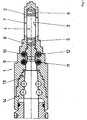
- the housing for the transmitter receptacle 1 consists of a housing tip 2 with a recording room 3 for a transmitter 4.
- the transmitter 4 is in the recording room embedded in damping elements 5,6. They can do this be designed that starting from an acceleration of the transmitter Tensile forces, for example, by a positive connection between Damper and transmitter are picked up by the damper.
- the top of the case 2 has slot-like transmission openings 7 on its peripheral surface Facilitate the exit of the transmission signals of the transmitter 4 from the recording room 3 of the housing tip 2.
- the housing tip 2 is designed as a drill head tip and in front of the main displacement head 8 of the housing 1 arranged.
- the housing 1 is in its outer shape is designed as a stepped head.
- the housing has 1 connecting means in its rear region 9, 10, 11, 12 including a receiving recess 13 for the head 14 a ram boring machine 15.
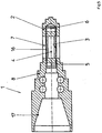
- the receiving recess 13 is corresponding to the usual step head or with a conical head 17 (FIG. 5) educated.
- the cone 17 can have an incline, which a self-locking connection between the transmitter housing 1 and Drill head 14 allows.
- the housing is used to plug the housing 1 onto the ram boring machine 15 with the receiving recess 13 on the step head 14 of the Ram ram pushed on and with fastening bolts 9,10,11,12 the drill head 14 fixed.
- the transmitter housing is removed in an equally simple manner by loosening the fastening bolts 9, 10, 11, 12 and removing the transmitter housing from the drill head 14 of the Ram drilling machine 15.
- the transmitter housing can be equipped with a movable displacement head steerable ram boring machine (Fig. 1,2) as well as with a rigid head one Standard ram boring machine (Fig. 3) are operated.
- the arranged in the housing tip 2 transmitter 4 must be due to the existing slot-like transmission openings 7 against the ingress of Dirt are protected. This can be done with the help of a surrounding the transmitter 4 Plastic sleeve 16 (Fig. 4) or by filling in the slot-like Openings are made with a non-shielding plastic compound.
Landscapes
- Life Sciences & Earth Sciences (AREA)
- Engineering & Computer Science (AREA)
- Geology (AREA)
- Mining & Mineral Resources (AREA)
- Physics & Mathematics (AREA)
- Environmental & Geological Engineering (AREA)
- Fluid Mechanics (AREA)
- General Life Sciences & Earth Sciences (AREA)
- Geochemistry & Mineralogy (AREA)
- Electromagnetism (AREA)
- Geophysics (AREA)
- Earth Drilling (AREA)
Applications Claiming Priority (2)
| Application Number | Priority Date | Filing Date | Title |
|---|---|---|---|
| DE19823629A DE19823629C2 (de) | 1998-05-27 | 1998-05-27 | Gehäuse zur Senderaufnahme |
| DE19823629 | 1998-05-27 |
Publications (2)
| Publication Number | Publication Date |
|---|---|
| EP0964133A1 true EP0964133A1 (fr) | 1999-12-15 |
| EP0964133B1 EP0964133B1 (fr) | 2003-07-30 |
Family
ID=7869037
Family Applications (1)
| Application Number | Title | Priority Date | Filing Date |
|---|---|---|---|
| EP99110095A Expired - Lifetime EP0964133B1 (fr) | 1998-05-27 | 1999-05-22 | Boítier pour transmetteur |
Country Status (2)
| Country | Link |
|---|---|
| EP (1) | EP0964133B1 (fr) |
| DE (1) | DE19823629C2 (fr) |
Cited By (1)
| Publication number | Priority date | Publication date | Assignee | Title |
|---|---|---|---|---|
| WO2002077406A1 (fr) * | 2001-03-17 | 2002-10-03 | Tracto-Technik Gmbh | Tete de foreuse a percussion |
Families Citing this family (2)
| Publication number | Priority date | Publication date | Assignee | Title |
|---|---|---|---|---|
| WO2006002997A1 (fr) * | 2004-07-06 | 2006-01-12 | Tracto-Technik Gmbh | Tete de forage d'un engin a forer le sol |
| DE102009043716B4 (de) | 2009-10-01 | 2020-04-02 | Tracto-Technik Gmbh & Co. Kg | Bohrelement einer Erdbohrvorrichtung |
Citations (3)
| Publication number | Priority date | Publication date | Assignee | Title |
|---|---|---|---|---|
| EP0361805A1 (fr) * | 1988-09-29 | 1990-04-04 | Gas Research Institute | Appareil de forage à percussion autopropulsé avec dispositif de transmission électronique |
| EP0391161A2 (fr) * | 1989-04-01 | 1990-10-10 | Tracto-Technik Paul Schmidt, Maschinenfabrik Kg | Dispositif automoteur de forage par battage |
| EP0617193A1 (fr) * | 1993-03-23 | 1994-09-28 | TERRA AG fuer Tiefbautechnik | Mouton de forage |
Family Cites Families (2)
| Publication number | Priority date | Publication date | Assignee | Title |
|---|---|---|---|---|
| GB8531382D0 (en) * | 1985-12-20 | 1986-02-05 | Kayes A G | Soil displacement hammer |
| DE8804347U1 (de) * | 1987-04-02 | 1988-06-01 | Holloway Equipment Sales Ltd., Gorseinon, West Glamorgan | Ortungsvorrichtung für Bodenverschiebungshämmer |
-
1998
- 1998-05-27 DE DE19823629A patent/DE19823629C2/de not_active Expired - Fee Related
-
1999
- 1999-05-22 EP EP99110095A patent/EP0964133B1/fr not_active Expired - Lifetime
Patent Citations (3)
| Publication number | Priority date | Publication date | Assignee | Title |
|---|---|---|---|---|
| EP0361805A1 (fr) * | 1988-09-29 | 1990-04-04 | Gas Research Institute | Appareil de forage à percussion autopropulsé avec dispositif de transmission électronique |
| EP0391161A2 (fr) * | 1989-04-01 | 1990-10-10 | Tracto-Technik Paul Schmidt, Maschinenfabrik Kg | Dispositif automoteur de forage par battage |
| EP0617193A1 (fr) * | 1993-03-23 | 1994-09-28 | TERRA AG fuer Tiefbautechnik | Mouton de forage |
Cited By (4)
| Publication number | Priority date | Publication date | Assignee | Title |
|---|---|---|---|---|
| WO2002077406A1 (fr) * | 2001-03-17 | 2002-10-03 | Tracto-Technik Gmbh | Tete de foreuse a percussion |
| GB2391240A (en) * | 2001-03-17 | 2004-02-04 | Tracto Technik | Percussion drill head |
| GB2391240B (en) * | 2001-03-17 | 2005-02-16 | Tracto Technik | Percussion drill head |
| US7093677B2 (en) | 2001-03-17 | 2006-08-22 | Tracto-Technik Gmbh | Percussion drill head |
Also Published As
| Publication number | Publication date |
|---|---|
| DE19823629A1 (de) | 1999-12-09 |
| DE19823629C2 (de) | 2001-08-02 |
| EP0964133B1 (fr) | 2003-07-30 |
Similar Documents
| Publication | Publication Date | Title |
|---|---|---|
| EP0601030B1 (fr) | Procede et dispositif pour l'execution de mesures dans des trous fores par cable | |
| DE60305733T2 (de) | Bohren eines bohrlochs | |
| DE102008026456B4 (de) | Bohrkopf | |
| DE102015105908A1 (de) | Bohrgerät zum Erstellen einer verrohrten Bohrung und Verfahren zum Betreiben eines Bohrgerätes | |
| DE102006043772B4 (de) | Verfahren und Vorrichtung zum Ersetzen erdverlegter Altleitungen | |
| EP2957710B1 (fr) | Tête de forage et dispositif de production d'un forage dans la terre | |
| EP0909876A2 (fr) | Système de transmission de données ou de courant électrique pour un appareil de forage | |
| DE4221221C1 (fr) | ||
| DE3935897A1 (de) | Verfahren und vorrichtung zum gesteinsbohren | |
| EP0429765A2 (fr) | Outil pour forage dirigé | |
| EP0964133B1 (fr) | Boítier pour transmetteur | |
| DE69907241T2 (de) | Nmr bohrlochmessvorrichtung | |
| DE3879045T2 (de) | Bodenprobennehmer. | |
| DE4438934C1 (de) | Ortungsvorrichtung für Rammbohrgeräte | |
| DE4142733C2 (de) | Bohrverfahren und Einrichtung zur Ausübung des Verfahrens | |
| DE1608274C3 (de) | Verfahren zum Überlagerungsbohren in Erdreich oder lockerem Gestein | |
| DE8804347U1 (de) | Ortungsvorrichtung für Bodenverschiebungshämmer | |
| DE4309387C1 (de) | Rammbohrgerät | |
| EP2483522B1 (fr) | Élément de forage d'un dispositif de sondage | |
| EP4110997A1 (fr) | Appareil et procédé d'essai au pénétromètre conique | |
| EP1407112A1 (fr) | Procede permettant de realiser des sondages | |
| DE102020130462B4 (de) | Verwendung eines Imlochhammers und einer Imlochhammervorrichtung | |
| EP4183974B1 (fr) | Système de tige creuse assisté par capteur | |
| DE2626654C3 (de) | Drehbohrmaschine für Bohrungen, insbesondere für Testbohrungen in gebirgsschlaggefährdeten Bereichen im Bergbau | |
| EP0563950A1 (fr) | Appareil et procédé pour le forage dirigé |
Legal Events
| Date | Code | Title | Description |
|---|---|---|---|
| PUAI | Public reference made under article 153(3) epc to a published international application that has entered the european phase |
Free format text: ORIGINAL CODE: 0009012 |
|
| AK | Designated contracting states |
Kind code of ref document: A1 Designated state(s): AT BE CH CY DE DK ES FI FR GB GR IE IT LI LU MC NL PT SE |
|
| AX | Request for extension of the european patent |
Free format text: AL;LT;LV;MK;RO;SI |
|
| 17P | Request for examination filed |
Effective date: 20000411 |
|
| AKX | Designation fees paid |
Free format text: FR GB |
|
| REG | Reference to a national code |
Ref country code: DE Ref legal event code: 8566 |
|
| 17Q | First examination report despatched |
Effective date: 20020809 |
|
| GRAH | Despatch of communication of intention to grant a patent |
Free format text: ORIGINAL CODE: EPIDOS IGRA |
|
| GRAH | Despatch of communication of intention to grant a patent |
Free format text: ORIGINAL CODE: EPIDOS IGRA |
|
| GRAA | (expected) grant |
Free format text: ORIGINAL CODE: 0009210 |
|
| AK | Designated contracting states |
Designated state(s): FR GB |
|
| REG | Reference to a national code |
Ref country code: GB Ref legal event code: FG4D Free format text: NOT ENGLISH |
|
| GBT | Gb: translation of ep patent filed (gb section 77(6)(a)/1977) | ||
| PG25 | Lapsed in a contracting state [announced via postgrant information from national office to epo] |
Ref country code: GB Free format text: LAPSE BECAUSE OF NON-PAYMENT OF DUE FEES Effective date: 20040522 |
|
| ET | Fr: translation filed | ||
| PLBE | No opposition filed within time limit |
Free format text: ORIGINAL CODE: 0009261 |
|
| STAA | Information on the status of an ep patent application or granted ep patent |
Free format text: STATUS: NO OPPOSITION FILED WITHIN TIME LIMIT |
|
| 26N | No opposition filed |
Effective date: 20040504 |
|
| GBPC | Gb: european patent ceased through non-payment of renewal fee |
Effective date: 20040522 |
|
| PG25 | Lapsed in a contracting state [announced via postgrant information from national office to epo] |
Ref country code: FR Free format text: LAPSE BECAUSE OF NON-PAYMENT OF DUE FEES Effective date: 20050131 |
|
| REG | Reference to a national code |
Ref country code: FR Ref legal event code: ST |