EP0964112B1 - Transparent panel for building improving the natural brightness inside the building - Google Patents
Transparent panel for building improving the natural brightness inside the building Download PDFInfo
- Publication number
- EP0964112B1 EP0964112B1 EP99401403A EP99401403A EP0964112B1 EP 0964112 B1 EP0964112 B1 EP 0964112B1 EP 99401403 A EP99401403 A EP 99401403A EP 99401403 A EP99401403 A EP 99401403A EP 0964112 B1 EP0964112 B1 EP 0964112B1
- Authority
- EP
- European Patent Office
- Prior art keywords
- grooves
- sheet
- panel
- glass
- building
- Prior art date
- Legal status (The legal status is an assumption and is not a legal conclusion. Google has not performed a legal analysis and makes no representation as to the accuracy of the status listed.)
- Expired - Lifetime
Links
Images


Classifications
-
- E—FIXED CONSTRUCTIONS
- E04—BUILDING
- E04C—STRUCTURAL ELEMENTS; BUILDING MATERIALS
- E04C2/00—Building elements of relatively thin form for the construction of parts of buildings, e.g. sheet materials, slabs, or panels
- E04C2/54—Slab-like translucent elements
-
- F—MECHANICAL ENGINEERING; LIGHTING; HEATING; WEAPONS; BLASTING
- F21—LIGHTING
- F21S—NON-PORTABLE LIGHTING DEVICES; SYSTEMS THEREOF; VEHICLE LIGHTING DEVICES SPECIALLY ADAPTED FOR VEHICLE EXTERIORS
- F21S11/00—Non-electric lighting devices or systems using daylight
Definitions
- the invention relates to a transparent panel intended to be mounted, particular, in a bay window of building and allowing to reorient the incident natural light rays so as to homogenize the luminosity at inside the building.
- the invention will be described more particularly for a building window in which will be mounted the transparent panel so as to redirect the natural light rays incident to the ceiling of the premises of the said building, but the invention is not limited to this type of application, any type of opening made in a building and able to receive a transparent panel between also in the context of the invention.
- a technique known to improve the level of natural light at the interior of a room is to divert the natural light rays incident by through a glazing so that at least some of these are reflect towards the ceiling of the room which reflects them to the interior of the room.
- the means used to deflect the rays bright incidents through glazing consist either in the use of Prisms made of a transparent material that refract the incident light ray in the use of metal surfaces that reflect the light beam incident.
- windows with a prismatic surface offer, as a window, a vision through said glazing which is deformed and the surface of the glazing which presents the series of prisms, is difficult to clean.
- WO 94/25792 teaches an optical component comprising two elements planes on which are arranged elementary surfaces able to reflect and / or refract the incident light.
- the present invention aims to provide a panel to be mounted, in particular, in a window bay of a building enabling the deflection of light rays incident at an angle greater than 45 ° in order to reorient the rays to the ceiling of the room and thus improve the brightness level to inside the room, offering a vision through it that is not distorted, which can be cleaned easily and can be implemented quickly and easily without finishing step of the surface state of the cuts.
- the invention thus proposes a transparent panel according to claim 1.
- the furrows present on the surface of the glass sheet are created by the creation cracks whose depth is controlled.
- Their inner surface is optically smooth and thus allows total reflection of incident natural light rays.
- the grooves are substantially perpendicular to the plane of the glass sheet.
- the grooves are distributed uniformly over the surface of the glass sheet.
- the glass sheet is part of a laminated panel and the depth of the grooves is equal to the thickness of the sheet of glass.
- the furrows are made directly on the whole laminated and the depth of the laser cutting grooves is advantageously controlled by the presence of the interlayer of the laminated panel, the rest of the glass sheet being held in place thanks to the same interlayer.
- the ratio of the depth of the furrows on the distance between two furrows is between 0.5 and 2 and, preferably, between 1 and 2. In this way, the number of spokes is optimized bright natural incidents that are going to be redirected.
- the transparent panel is part of multiple insulation glazing.
- the surface of the panel presenting the grooves is in contact with the gas strip of the multiple insulating glazing and is thus protected from dust and moisture.
- such a variant makes it possible to to realize a multiple insulating glazing combining the insulating performances with the advantages of glazing improving the brightness of a room.
- the transparent panel allows, as explained above, to deviate light rays incident at an angle greater than 45 ° so as to redirect the rays to the ceiling of the room and thus improve the level of brightness natural inside the premises.
- Such a panel also makes it possible to obtain a vision through without deformations.
- Figure 1 shows a portion of a vertical section of a panel 1 according to the invention.
- the panel 1 consists of a glass sheet 2 on which a series of grooves 3 has been made by a laser cutting technique such as, for example, by the technique described in the European patent EP-B -0,633,867.
- the grooves 3 have, for example, a depth of 0.8 mm for a total thickness of the glass sheet 2 of 2 mm.
- the grooves 3 are arranged horizontally in relation to the general plane of the glass sheet 2 and are parallel to each other and spaced from each other by a step of 0.5 mm per example, a depth / step ratio of 1.6.
- the grooves 3 are perpendicular to the plane of the glass sheet 2 and are delimited by two internal faces 4 and 5.
- These internal faces 4 and 5 represent the walls of the crack generated by laser beam and are distant from each other, but sufficiently close to stay invisible to the eye.
- An incident light beam 6 comes into contact with the glass sheet 2 on its face 7, it is deflected by refraction at the face 7, then by refraction at the inner face 4 of groove 3 and again by refraction at level of the face 8 of the glass sheet 2.
- Figure 2 shows a portion of a vertical section of another type of panel 1 according to the invention.
- the panel 1 consists of two sheets of 10 and 11 together by means of a tab 12.
- This tab 12 is, for example, a polyvinyl butyral (PVB) sheet.
- the glass sheet 11 has a series of grooves 3 identical to that of the 1, with the difference that the glass sheet 11 is less thick than the sheet of glass 2, its thickness being identical to the depth of the grooves.
- the glass sheet 10 has a thickness greater than that of the glass sheet 11 and thus, serves as a support for the entire panel 1.
- the glass sheet 10 has a thickness of 4 mm and the glass sheet 11 a thickness of 0.8 mm.
- Figure 3 shows a vertical section of a building room on which the panel 1 according to the invention was mounted as a window.
- the radius 12 has a small angle of incidence, and crosses the panel 1 without significant deviation by simple refraction. So, the background of the room remains illuminated.
- the radius 13 presents, on the other hand, a wide angle of incidence and is deflected as it passes through the panel 1 towards the ceiling of the room, said ceiling then diffusely reflecting the radius 13 to the entire premises.
- the incident light rays arrives according to a wide angle, the brightness of the room remains homogeneous.
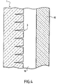
- FIG. 4 represents a part of a vertical section of a double insulating glazing in which the panel 1 according to the invention has been inserted.
- the double insulating glazing consists of transparent panel 1 according to the invention and a glass sheet 15, the panel 1 and the glass sheet 15 being separated from each other by an air knife 16 and united at their periphery through a profiled frame here not shown on the figure and known to those skilled in the art.
- the grooves 3 of the panel 1 are in contact with the air knife 16.
Abstract
Description
L'invention concerne un panneau transparent destiné à être monté, notamment, dans une baie de fenêtre de bâtiment et permettant de réorienter les rayons lumineux naturels incidents de manière à homogénéiser la luminosité à l'intérieur du bâtiment.The invention relates to a transparent panel intended to be mounted, particular, in a bay window of building and allowing to reorient the incident natural light rays so as to homogenize the luminosity at inside the building.
L'invention sera décrite plus particulièrement pour une fenêtre de bâtiment dans laquelle sera montée le panneau transparent de manière à réorienter les rayons lumineux naturels incidents vers le plafond du local dudit bâtiment, mais l'invention ne se limite pas à ce type d'application, tout type d'ouverture réalisée dans un bâtiment et apte à recevoir un panneau transparent entre également dans le cadre de l'invention.The invention will be described more particularly for a building window in which will be mounted the transparent panel so as to redirect the natural light rays incident to the ceiling of the premises of the said building, but the invention is not limited to this type of application, any type of opening made in a building and able to receive a transparent panel between also in the context of the invention.
Une technique connue pour améliorer le niveau de lumière naturelle à l'intérieur d'un local consiste à dévier les rayons lumineux naturels incidents par l'intermédiaire d'un vitrage de sorte qu'au moins une partie de ceux-ci soient réfléchis vers le plafond du local qui les refléchit à son tour vers l'intérieur du local. Ainsi, on augmente le niveau de lumière naturelle dans l'ensemble du local en modifiant la répartition des rayons lumineux, en particulier au niveau des zones du local qui sont éloignées de la fenêtre.A technique known to improve the level of natural light at the interior of a room is to divert the natural light rays incident by through a glazing so that at least some of these are reflect towards the ceiling of the room which reflects them to the interior of the room. Thus, we increase the level of natural light throughout the local area. altering the distribution of light rays, especially at the level of local who are far from the window.
De façon traditionnelle, les moyens employés pour dévier les rayons lumineux incidents par l'intermédiaire d'un vitrage consistent soit en l'utilisation de prismes faits d'un matériau transparent qui réfractent le rayon lumineux incident soit en l'utilisation de surfaces métalliques qui réfléchissent le rayon lumineux incident. In the traditional way, the means used to deflect the rays bright incidents through glazing consist either in the use of Prisms made of a transparent material that refract the incident light ray in the use of metal surfaces that reflect the light beam incident.
En particulier, il est connu d'employer des vitrages dont une face est moulée de manière à former une série de prismes. Cependant, de tels vitrages à surface prismatique ne permettent pas de dévier les rayons lumineux d'un angle supérieur à 45° et il s'avère qu'une déviation d'un angle supérieur à 45° des rayons solaires est souvent nécessaire pour que ceux-ci puissent être dirigés vers le plafond du local.In particular, it is known to use glazing with a face molded from to form a series of prisms. However, such surface glazing prismatic can not deflect the light rays from a higher angle at 45 ° and it turns out that a deviation from an angle greater than 45 ° of solar rays is often necessary so that they can be directed to the ceiling of the local.
Par ailleurs, de tels vitrages à surface prismatique offrent, en tant que fenêtre, une vision au travers dudit vitrage qui est déformée et la surface du vitrage qui présente la série de prismes, est difficile à nettoyer.Moreover, such windows with a prismatic surface offer, as a window, a vision through said glazing which is deformed and the surface of the glazing which presents the series of prisms, is difficult to clean.
Il est également connu d'employer des réflecteurs métalliques intégrés dans un vitrage sous la forme d'une jalousie. Cependant, de tels réflecteurs métalliques ne sont pas totalement satisfaisants. En effet, l'angle de réflexion du rayon lumineux dépend fortement de l'angle d'incidence de la lumière et les surfaces réfléchissantes sont difficiles à nettoyer et présentent un encombrement important. Le brevet américain US 4,989,952 a déjà proposé un panneau plat en plastique transparent présentant une pluralité de découpes laser parallèles et espacées les unes des autres d'un pas régulier, ces découpes étant réalisées perpendiculairement au panneau de manière à diviser le panneau en parallélépipèdes sur au moins une partie de son épaisseur. Les découpes sont protégées des poussières à l'aide d'une feuille mince transparente fixée audit panneau.It is also known to employ metal reflectors integrated into a glazing in the form of a jealousy. However, such metal reflectors are not totally satisfactory. Indeed, the angle of reflection of the light ray strongly depends on the angle of incidence of the light and the surfaces reflective are difficult to clean and have a large footprint. US Pat. No. 4,989,952 has already proposed a plastic flat panel having a plurality of parallel laser cutouts and spaced apart each other with a regular step, these cuts being made perpendicular to the panel so as to divide the panel into parallelepipeds on at least a part of its thickness. The cuts are protected from dust using a transparent thin sheet attached to the audit sign.
Cependant, une telle solution n'est pas totalement satisfaisante d'un point de vue optique. En effet, pour obtenir une réflexion spéculaire des rayons lumineux incidents, il est nécessaire que les faces internes des découpes au laser soient parfaitement lisses. Il est connu que la découpe laser d'une matière plastique ne permet pas d'obtenir une surface optiquement parfaitement lisse et cela du fait que, sous l'action du laser, la matière plastique fond et ne permet pas de créer un découpe nette et franche. Il s'avère donc nécessaire d'effectuer une étape supplémentaire afin de rendre les surfaces internes des découpes optiquement adéquates. Or une telle étape supplémentaire est contraignante et n'est pas toujours aisément réalisable du fait de la taille des découpes.However, such a solution is not totally satisfactory from a point of view optical. Indeed, to obtain a specular reflection of light rays incidents, it is necessary that the internal faces of the laser cutouts be perfectly smooth. It is known that the laser cutting of a material plastic does not provide an optically perfectly smooth surface and this is because, under the action of the laser, the plastic material melts and does not allow to create a crisp and clean cut. It is therefore necessary to carry out a extra step in order to make the internal surfaces of the cuts optically adequate. But such an additional step is binding and is not always easily achievable because of the size of the cuts.
Le WO 94/25792 enseigne un composant optique comprenant deux éléments plans sur lesquels sont disposés des surfaces élémentaires capables de refléter et/ou réfracter la lumière incidente.WO 94/25792 teaches an optical component comprising two elements planes on which are arranged elementary surfaces able to reflect and / or refract the incident light.
La présente invention a pour but de fournir un panneau destiné à être monté, notamment, dans une baie de fenêtre d'un bâtiment permettant de dévier des rayons lumineux incidents d'un angle supérieur à 45° de manière à réorienter les rayons vers le plafond du local et ainsi d'améliorer le niveau de luminosité à l'intérieur du local, offrant une vision au travers de celui-ci qui n'est pas déformée, pouvant être nettoyé sans difficultés et pouvant être mis en oeuvre rapidement et facilement sans étape de finition de l'état de surface des découpes.The present invention aims to provide a panel to be mounted, in particular, in a window bay of a building enabling the deflection of light rays incident at an angle greater than 45 ° in order to reorient the rays to the ceiling of the room and thus improve the brightness level to inside the room, offering a vision through it that is not distorted, which can be cleaned easily and can be implemented quickly and easily without finishing step of the surface state of the cuts.
L'invention propose ainsi un panneau transparent conforme à la revendication 1. Les sillons présents à la surface de la feuille de verre sont réalisés par la création de fissures dont on contrôle la profondeur. Leur surface interne est optiquement lisse et permet ainsi une réflexion totale des rayons lumineux naturels incidents.The invention thus proposes a transparent panel according to claim 1. The furrows present on the surface of the glass sheet are created by the creation cracks whose depth is controlled. Their inner surface is optically smooth and thus allows total reflection of incident natural light rays.
Selon une variante avantageuse de l'invention, les sillons sont sensiblement perpendiculaires au plan de la feuille de verre.According to an advantageous variant of the invention, the grooves are substantially perpendicular to the plane of the glass sheet.
De préférence, les sillons sont répartis de manière uniforme sur la surface de la feuille de verre.Preferably, the grooves are distributed uniformly over the surface of the glass sheet.
Selon une variante avantageuse de l'invention, la feuille de verre fait partie d'un panneau feuilleté et la profondeur des sillons est égale à l'épaisseur de la feuille de verre. De cette façon, les sillons sont réalisés directement sur l'ensemble feuilleté et la profondeur de la découpe laser des sillons est avantageusement contrôlée par la présence de l'intercalaire du panneau feuilleté, le reste de la feuille de verre étant maintenu en place grâce au même intercalaire. According to an advantageous variant of the invention, the glass sheet is part of a laminated panel and the depth of the grooves is equal to the thickness of the sheet of glass. In this way, the furrows are made directly on the whole laminated and the depth of the laser cutting grooves is advantageously controlled by the presence of the interlayer of the laminated panel, the rest of the glass sheet being held in place thanks to the same interlayer.
Selon une réalisation préférée de l'invention, le ratio de la profondeur des sillons sur la distance entre deux sillons est compris entre 0,5 et 2 et, de préférence, entre 1 et 2. De cette manière, on optimise le nombre de rayons lumineux naturels incidents qui vont être réorientés.According to a preferred embodiment of the invention, the ratio of the depth of the furrows on the distance between two furrows is between 0.5 and 2 and, preferably, between 1 and 2. In this way, the number of spokes is optimized bright natural incidents that are going to be redirected.
Selon une variante préférée de l'invention, le panneau transparent fait parti d'un vitrage multiple isolant. De cette façon, la surface du panneau présentant les sillons est en contact avec la lame de gaz du vitrage multiple isolant et est ainsi protégée des poussières et de l'humidité. De plus, une telle variante permet de réaliser un vitrage multiple isolant combinant les performances isolantes avec les avantages d'un vitrage améliorant la luminosité d'un local.According to a preferred variant of the invention, the transparent panel is part of multiple insulation glazing. In this way, the surface of the panel presenting the grooves is in contact with the gas strip of the multiple insulating glazing and is thus protected from dust and moisture. In addition, such a variant makes it possible to to realize a multiple insulating glazing combining the insulating performances with the advantages of glazing improving the brightness of a room.
Le panneau transparent permet, comme explicité précédemment, de dévier des rayons lumineux incidents d'un angle supérieur à 45° de manière à réorienter les rayons vers le plafond du local et ainsi améliorer le niveau de luminosité naturelle à l'intérieur du local. Un tel panneau permet également d'obtenir une vision au travers sans déformations.The transparent panel allows, as explained above, to deviate light rays incident at an angle greater than 45 ° so as to redirect the rays to the ceiling of the room and thus improve the level of brightness natural inside the premises. Such a panel also makes it possible to obtain a vision through without deformations.
D'autres détails et caractéristiques avantageuses de l'invention ressortiront, ci-après, de la description d'exemples de réalisation de l'invention en référence aux figures 1, 2, 3 et 4 qui représentent :
- Figure 1 : une coupe verticale d'un panneau selon l'invention.
- Figure 2 : une coupe verticale d'un autre type de panneau selon l'invention.
- Figure 3 : une coupe verticale d'un local de bâtiment sur lequel le panneau selon l'invention a été monté en tant que fenêtre.
- Figure 4 : une coupe verticale d'un vitrage double dans lequel a été inséré le panneau selon l'invention.
- Figure 1 : a vertical section of a panel according to the invention.
- Figure 2 : a vertical section of another type of panel according to the invention.
- Figure 3 : a vertical section of a building room on which the panel according to the invention was mounted as a window.
- Figure 4 : a vertical section of a double glazing in which was inserted the panel according to the invention.
On précise tout d'abord que, par souci de clarté, toutes les figures ne respectent pas rigoureusement les proportions entre les divers éléments représentés.First of all, for the sake of clarity, not all figures strictly respect the proportions between the various elements represented.
La figure 1 représente une partie d'une coupe verticale d'un panneau 1 selon l'invention. Figure 1 shows a portion of a vertical section of a panel 1 according to the invention.
Selon cette représentation, la panneau 1 est constitué d'une feuille de verre
2 sur laquelle une série de sillons 3 a été réalisée par une technique de découpe
au laser telle que, par exemple, par la technique décrite dans le brevet européen
EP-B-0 633 867. According to this representation, the panel 1 consists of a glass sheet 2 on which a series of
Les sillons 3 ont, par exemple, une profondeur de 0,8 mm pour une
épaisseur totale de la feuille de verre 2 de 2 mm. Les sillons 3 sont disposés
horizontalement par rapport au plan général de la feuille de verre 2 et sont
parallèles entre-eux et distants les uns des autres d'un pas de 0,5 mm par
exemple, soit un ratio profondeur/pas de 1,6.The
Selon cette représentation, les sillons 3 sont perpendiculaires au plan
général de la feuille de verre 2 et sont délimités par deux faces internes 4 et 5.According to this representation, the
Ces faces internes 4 et 5 représentent les parois de la fissure générée par rayon laser et sont distantes l'une de l'autre, mais de manière suffisamment proches de manière à rester invisible à l'oeil.These internal faces 4 and 5 represent the walls of the crack generated by laser beam and are distant from each other, but sufficiently close to stay invisible to the eye.
Un rayon lumineux 6 incident arrive au contact de la feuille de verre 2 sur
sa face 7, il est dévié par réfraction au niveau de la face 7, puis par réfraction
totale au niveau de la face interne 4 du sillon 3 et à nouveau par réfraction au
niveau de la face 8 de la feuille de verre 2.An incident light beam 6 comes into contact with the glass sheet 2 on
its face 7, it is deflected by refraction at the face 7, then by refraction
at the inner face 4 of
Un autre rayon lumineux 9 incident arrive en contact avec la feuille de verre
2 mais sous un angle incident beaucoup plus faible, celui-ci est alors dévié
uniquement par réfraction au niveau des faces 7 et 8 de la feuille de verre 2, pour
autant qu'il ne rencontre pas de sillon 3.Another incident light ray comes into contact with the glass sheet
But at a much smaller incident angle, it is
only by refraction at the faces 7 and 8 of the glass sheet 2, for
as long as it does not encounter a
De cette manière, on observe que les rayons lumineux ayant un grand angle d'incidence, sont totalement déviés vers le plafond du local et que les rayons lumineux ayant un petit angle d'incidence ne sont pas obligatoirement réfléchis par les faces internes 4 des sillons. Ainsi, quel que soit l'angle d'incidence, on garde une constance en luminosité dans l'ensemble du local.In this way, it is observed that light rays having a large angle of incidence, are totally deviated towards the ceiling of the room and that the light rays having a small angle of incidence are not necessarily reflected by the internal faces 4 of the grooves. So, whatever the angle incidence, we keep a constant brightness in the entire room.
Par ailleurs, il est évident que tous les rayons réfractés au niveau de la face
7 de la feuille de verre 2 dans une direction parallèle aux sillons 3 vont traversés
le panneau 1 sans être déviés. Ainsi, la vision au travers du panneau 1 dans des
directions sensiblement parallèles aux angles des découpes 3 ne va pas être
déformée.Moreover, it is obvious that all the refracted rays at the level of the face
7 of the glass sheet 2 in a direction parallel to the
La figure 2 représente une partie d'une coupe verticale d'un autre type de panneau 1 selon l'invention. Figure 2 shows a portion of a vertical section of another type of panel 1 according to the invention.
Selon cette représentation, le panneau 1 est constitué de deux feuilles de
verre 10 et 11 réunies ensemble par l'intermédiaire d'un intercalaire 12. Cet
intercalaire 12 est, par exemple, une feuille de polyvinylbutyral (PVB). On observe
que la feuille de verre 11 présente une série de sillons 3 identique à celle de la
figure 1, à la différence que la feuille de verre 11 est moins épaisse que la feuille
de verre 2, son épaisseur étant identique à la profondeur des sillons.
Avantageusement, la feuille de verre 10 présente une épaisseur supérieure à
celle de la feuille de verre 11 et ainsi, sert de support à l'ensemble du panneau 1.
Par exemple, la feuille de verre 10 a une épaisseur de 4 mm et la feuille de verre
11 une épaisseur de 0,8 mm.According to this representation, the panel 1 consists of two sheets of
10 and 11 together by means of a
La figure 3 représente une coupe verticale d'un local de bâtiment sur lequel le panneau 1 selon l'invention a été monté en tant que fenêtre. Figure 3 shows a vertical section of a building room on which the panel 1 according to the invention was mounted as a window.
Selon cette représentation, on observe clairement le chemin suivi par deux
types de rayon incident. Le rayon 12 présente un petit angle d'incidence, et
traverse le panneau 1 sans déviation importante par simple réfraction. Ainsi, le
fond du local reste illuminé. Le rayon 13 présente, par contre, un grand angle
d'incidence et est dévié lors de son passage au travers du panneau 1 vers le
plafond du local, ledit plafond réfléchissant alors de manière diffuse le rayon 13
vers l'ensemble du local. Ainsi, lorsque les rayons lumineux incidents arrive selon
un grand angle, la luminosité de la pièce reste homogène.According to this representation, we clearly observe the path followed by two
types of incident ray. The
Afin de mieux comparer les avantages du panneau 1 selon l'invention, nous
avons représenté en pointillé le chemin qu'aurait effectué le rayon 13 en
traversant une feuille de verre banale, ce chemin étant référencé 14. Par ailleurs,
il est évident que le rayon 12 qui passerait au travers d'une banale feuille de
verre, suiverait le même chemin que celui représenté sur la figure.In order to better compare the advantages of panel 1 according to the invention, we
have represented in dotted line the path that would have made the
La figure 4 représente une partie d'une coupe verticale d'un vitrage double isolant dans lequel a été inséré le panneau 1 selon l'invention. FIG. 4 represents a part of a vertical section of a double insulating glazing in which the panel 1 according to the invention has been inserted.
Selon cette représentation, le vitrage double isolant est constitué du
panneau transparent 1 selon l'invention et d'une feuille de verre 15, le panneau 1
et la feuille de verre 15 étant séparés l'un de l'autre par une lame d'air 16 et réunis
à leur périphérie par l'intermédiaire d'un cadre profilé ici non représenté sur la
figure et connu de l'homme du métier. De manière avantageuse, les sillons 3 du
panneau 1 sont en contact avec la lame d'air 16. Une telle réalisation permet
d'obtenir un vitrage isolant connu qui permet, en plus, de réorienter les rayons
lumineux incidents et cela sans augmenter l'épaisseur totale du vitrage isolant.According to this representation, the double insulating glazing consists of
transparent panel 1 according to the invention and a glass sheet 15, the panel 1
and the glass sheet 15 being separated from each other by an
L'invention ne se limite pas à ces types de réalisation et doit être interprétée de façon non limitative et englobant tout type de panneau transparent dans la portée des panneaux revendiqués.The invention is not limited to these types of embodiments and must be interpreted non-limiting way and encompassing any type of transparent panel in the scope claimed panels.
Claims (9)
- Transparent panel intended to be mounted, in particular, in a window opening in a building and reorienting the natural incident light rays so as to make the brightness inside the building uniform, comprising at least one sheet having, over at least part of its thickness, grooves disposed horizontally in the position of use and parallel to each other,
characterised in that
the sheet is made from glass, and the said grooves are invisible to the eye and were cut by laser by the creation of fissures. - Panel according to the preceding claim, characterised in that the grooves are substantially perpendicular to the plane of the sheet of glass.
- Panel according to one of the preceding claims, characterised in that the grooves are distributed uniformly on the surface of the sheet of glass.
- Panel according to one of the preceding claims, characterised in that it is laminated and in that the depth of the grooves is equal to the thickness of the sheet of glass.
- Panel according to one of the preceding claims, characterised in that it is laminated, and in that it comprises two sheets of glass, one of which comprises the grooves, and an insert between the two sheets of glass.
- Panel according to one of Claims 4 or 5, characterised in that the insert is a sheet of polyvinyl butyral and in that a sheet comprising the grooves is less thick than another sheet without grooves.
- Panel according to one of the preceding claims, characterised in that the ratio of the depth of the grooves to the distance between two grooves is between 0.5 and 2 and preferably between 1 and 2.
- Multiple insulating glazing comprising a layer of air, characterised in that it comprises a panel according to one of the preceding claims.
- Glazing according to the preceding claim, characterised in that the surface of the panel having the grooves is in contact with the layer of air.
Applications Claiming Priority (2)
| Application Number | Priority Date | Filing Date | Title |
|---|---|---|---|
| FR9807275A FR2779755B1 (en) | 1998-06-10 | 1998-06-10 | TRANSPARENT PANEL FOR A BUILDING IMPROVING NATURAL BRIGHTNESS INSIDE THE BUILDING |
| FR9807275 | 1998-06-10 |
Publications (2)
| Publication Number | Publication Date |
|---|---|
| EP0964112A1 EP0964112A1 (en) | 1999-12-15 |
| EP0964112B1 true EP0964112B1 (en) | 2004-01-21 |
Family
ID=9527212
Family Applications (1)
| Application Number | Title | Priority Date | Filing Date |
|---|---|---|---|
| EP99401403A Expired - Lifetime EP0964112B1 (en) | 1998-06-10 | 1999-06-10 | Transparent panel for building improving the natural brightness inside the building |
Country Status (6)
| Country | Link |
|---|---|
| EP (1) | EP0964112B1 (en) |
| AT (1) | ATE258257T1 (en) |
| DE (1) | DE69914256T2 (en) |
| ES (1) | ES2213990T3 (en) |
| FR (1) | FR2779755B1 (en) |
| PT (1) | PT964112E (en) |
Families Citing this family (1)
| Publication number | Priority date | Publication date | Assignee | Title |
|---|---|---|---|---|
| CN112659055A (en) * | 2020-12-15 | 2021-04-16 | 南京凡芽智能设备有限公司 | Method for manufacturing and processing building glass curtain wall |
Family Cites Families (7)
| Publication number | Priority date | Publication date | Assignee | Title |
|---|---|---|---|---|
| IL65514A (en) * | 1982-04-18 | 1986-10-31 | Yitzchak Bar Yonah | Selectively light transmitting panel for buildings |
| NZ224424A (en) * | 1987-11-06 | 1990-12-21 | Ian Robert Edmonds | Light deflecting window panel: parallel cuts in transparent material by laser |
| JP3217385B2 (en) * | 1991-02-21 | 2001-10-09 | 株式会社小坂研究所 | How to cut glass panels |
| DE4134955A1 (en) * | 1991-10-23 | 1993-04-29 | Helmut Frank Ottomar P Mueller | LIGHT GUIDE |
| RU2024441C1 (en) * | 1992-04-02 | 1994-12-15 | Владимир Степанович Кондратенко | Process of cutting of nonmetal materials |
| DE4218215A1 (en) * | 1992-06-03 | 1993-12-09 | Ver Glaswerke Gmbh | Glass block with diffuse light scattering |
| US5880886A (en) * | 1993-05-04 | 1999-03-09 | Milner; Peter James | Optical component suitable for use in glazing |
-
1998
- 1998-06-10 FR FR9807275A patent/FR2779755B1/en not_active Expired - Lifetime
-
1999
- 1999-06-10 EP EP99401403A patent/EP0964112B1/en not_active Expired - Lifetime
- 1999-06-10 DE DE1999614256 patent/DE69914256T2/en not_active Expired - Lifetime
- 1999-06-10 PT PT99401403T patent/PT964112E/en unknown
- 1999-06-10 ES ES99401403T patent/ES2213990T3/en not_active Expired - Lifetime
- 1999-06-10 AT AT99401403T patent/ATE258257T1/en active
Also Published As
| Publication number | Publication date |
|---|---|
| EP0964112A1 (en) | 1999-12-15 |
| FR2779755A1 (en) | 1999-12-17 |
| DE69914256D1 (en) | 2004-02-26 |
| FR2779755B1 (en) | 2000-07-21 |
| ES2213990T3 (en) | 2004-09-01 |
| ATE258257T1 (en) | 2004-02-15 |
| DE69914256T2 (en) | 2004-11-18 |
| PT964112E (en) | 2004-06-30 |
Similar Documents
| Publication | Publication Date | Title |
|---|---|---|
| EP3600884B1 (en) | Illuminating glazing | |
| EP0945674B1 (en) | Luminous edge-lit device | |
| EP2045515B1 (en) | Lighting or signalling device for an automobile | |
| FR3034501A1 (en) | LUMINOUS GLAZING FOR BUILDING, FURNITURE, PUBLIC TRANSPORT VEHICLE | |
| LU86377A1 (en) | TRANSPARENT GLASS | |
| FR2955915A1 (en) | LUMINOUS MULTIPLE GLAZING WITH LIGHT EMITTING DIODES | |
| FR2932307A1 (en) | DEVICE FOR DISPLAYING A VIDEO IMAGE ON AN EDIFICE | |
| FR2961609A1 (en) | DEVICE HAVING ELECTRO-CONTROLLABLE OPTICAL AND / OR ENERGY PROPERTIES | |
| EP1654912A1 (en) | Luminous element comprising at least one substrate and a light-emitting coating | |
| WO2007057456A1 (en) | Light radiation emitting panel | |
| EP0838628B1 (en) | Motor vehicle headlamp comprising a light conducting element | |
| EP0964112B1 (en) | Transparent panel for building improving the natural brightness inside the building | |
| EP2945917B1 (en) | Textured glass substrate for a building | |
| FR3069241B1 (en) | MATERIAL COMPRISING A STACK WITH THERMAL PROPERTIES | |
| FR2964176A1 (en) | DECORATIVE AND LIGHTING PANEL WITH ELECTROLUMINESCENT DIODES | |
| WO2012028813A1 (en) | Illuminating multiple glazing including light-emitting diodes | |
| EP0878661B1 (en) | Glass element for space illumination with daylight | |
| EP2646753B1 (en) | Airlock comprising a lighting device | |
| AU601634B2 (en) | A window panel for improved daylighting of room interiors | |
| FR2542063A1 (en) | Anti-dazzle lighting device | |
| WO2011070287A1 (en) | Element, especially for a building façade, comprising a glass pane and light-emitting diodes | |
| EP0232494A1 (en) | Panel for a building element | |
| WO2023247876A1 (en) | Illuminating glass structure | |
| FR3053629A1 (en) | GLAZED GLAZING FOR ROOF OF MOTOR VEHICLE | |
| EP0230854A1 (en) | Transparent panel forming a part of a room in an architectural construction |
Legal Events
| Date | Code | Title | Description |
|---|---|---|---|
| PUAI | Public reference made under article 153(3) epc to a published international application that has entered the european phase |
Free format text: ORIGINAL CODE: 0009012 |
|
| AK | Designated contracting states |
Kind code of ref document: A1 Designated state(s): AT BE CH DE DK ES FI FR GB GR IE IT LI LU NL PT SE |
|
| AX | Request for extension of the european patent |
Free format text: AL;LT;LV;MK;RO;SI |
|
| 17P | Request for examination filed |
Effective date: 20000526 |
|
| AKX | Designation fees paid |
Free format text: AT BE CH DE DK ES FI LI |
|
| RBV | Designated contracting states (corrected) |
Designated state(s): AT BE CH DE DK ES FI FR GB GR IE IT LI LU NL PT SE |
|
| RAP1 | Party data changed (applicant data changed or rights of an application transferred) |
Owner name: SAINT-GOBAIN GLASS FRANCE |
|
| 17Q | First examination report despatched |
Effective date: 20020729 |
|
| GRAP | Despatch of communication of intention to grant a patent |
Free format text: ORIGINAL CODE: EPIDOSNIGR1 |
|
| GRAS | Grant fee paid |
Free format text: ORIGINAL CODE: EPIDOSNIGR3 |
|
| GRAA | (expected) grant |
Free format text: ORIGINAL CODE: 0009210 |
|
| AK | Designated contracting states |
Kind code of ref document: B1 Designated state(s): AT BE CH DE DK ES FI FR GB GR IE IT LI LU NL PT SE |
|
| PG25 | Lapsed in a contracting state [announced via postgrant information from national office to epo] |
Ref country code: IE Free format text: LAPSE BECAUSE OF FAILURE TO SUBMIT A TRANSLATION OF THE DESCRIPTION OR TO PAY THE FEE WITHIN THE PRESCRIBED TIME-LIMIT Effective date: 20040121 Ref country code: FI Free format text: LAPSE BECAUSE OF FAILURE TO SUBMIT A TRANSLATION OF THE DESCRIPTION OR TO PAY THE FEE WITHIN THE PRESCRIBED TIME-LIMIT Effective date: 20040121 |
|
| REG | Reference to a national code |
Ref country code: GB Ref legal event code: FG4D Free format text: NOT ENGLISH |
|
| REG | Reference to a national code |
Ref country code: CH Ref legal event code: EP |
|
| REG | Reference to a national code |
Ref country code: IE Ref legal event code: FG4D Free format text: FRENCH |
|
| REF | Corresponds to: |
Ref document number: 69914256 Country of ref document: DE Date of ref document: 20040226 Kind code of ref document: P |
|
| PG25 | Lapsed in a contracting state [announced via postgrant information from national office to epo] |
Ref country code: GR Free format text: LAPSE BECAUSE OF FAILURE TO SUBMIT A TRANSLATION OF THE DESCRIPTION OR TO PAY THE FEE WITHIN THE PRESCRIBED TIME-LIMIT Effective date: 20040421 Ref country code: DK Free format text: LAPSE BECAUSE OF FAILURE TO SUBMIT A TRANSLATION OF THE DESCRIPTION OR TO PAY THE FEE WITHIN THE PRESCRIBED TIME-LIMIT Effective date: 20040421 |
|
| REG | Reference to a national code |
Ref country code: SE Ref legal event code: TRGR |
|
| GBT | Gb: translation of ep patent filed (gb section 77(6)(a)/1977) |
Effective date: 20040423 |
|
| PG25 | Lapsed in a contracting state [announced via postgrant information from national office to epo] |
Ref country code: LI Free format text: LAPSE BECAUSE OF NON-PAYMENT OF DUE FEES Effective date: 20040630 Ref country code: CH Free format text: LAPSE BECAUSE OF NON-PAYMENT OF DUE FEES Effective date: 20040630 |
|
| REG | Reference to a national code |
Ref country code: PT Ref legal event code: SC4A Free format text: AVAILABILITY OF NATIONAL TRANSLATION Effective date: 20040414 |
|
| REG | Reference to a national code |
Ref country code: IE Ref legal event code: FD4D |
|
| REG | Reference to a national code |
Ref country code: ES Ref legal event code: FG2A Ref document number: 2213990 Country of ref document: ES Kind code of ref document: T3 |
|
| PLBE | No opposition filed within time limit |
Free format text: ORIGINAL CODE: 0009261 |
|
| STAA | Information on the status of an ep patent application or granted ep patent |
Free format text: STATUS: NO OPPOSITION FILED WITHIN TIME LIMIT |
|
| 26N | No opposition filed |
Effective date: 20041022 |
|
| REG | Reference to a national code |
Ref country code: CH Ref legal event code: PL |
|
| PG25 | Lapsed in a contracting state [announced via postgrant information from national office to epo] |
Ref country code: LU Free format text: LAPSE BECAUSE OF NON-PAYMENT OF DUE FEES Effective date: 20140610 |
|
| REG | Reference to a national code |
Ref country code: FR Ref legal event code: PLFP Year of fee payment: 18 |
|
| REG | Reference to a national code |
Ref country code: FR Ref legal event code: PLFP Year of fee payment: 19 |
|
| REG | Reference to a national code |
Ref country code: FR Ref legal event code: PLFP Year of fee payment: 20 |
|
| PGFP | Annual fee paid to national office [announced via postgrant information from national office to epo] |
Ref country code: NL Payment date: 20180613 Year of fee payment: 20 Ref country code: PT Payment date: 20180604 Year of fee payment: 20 Ref country code: DE Payment date: 20180530 Year of fee payment: 20 Ref country code: LU Payment date: 20180625 Year of fee payment: 20 |
|
| PGFP | Annual fee paid to national office [announced via postgrant information from national office to epo] |
Ref country code: AT Payment date: 20180525 Year of fee payment: 20 Ref country code: FR Payment date: 20180625 Year of fee payment: 20 Ref country code: BE Payment date: 20180626 Year of fee payment: 20 |
|
| PGFP | Annual fee paid to national office [announced via postgrant information from national office to epo] |
Ref country code: SE Payment date: 20180612 Year of fee payment: 20 |
|
| PGFP | Annual fee paid to national office [announced via postgrant information from national office to epo] |
Ref country code: GB Payment date: 20180606 Year of fee payment: 20 Ref country code: ES Payment date: 20180702 Year of fee payment: 20 Ref country code: IT Payment date: 20180625 Year of fee payment: 20 |
|
| REG | Reference to a national code |
Ref country code: DE Ref legal event code: R071 Ref document number: 69914256 Country of ref document: DE |
|
| REG | Reference to a national code |
Ref country code: NL Ref legal event code: MK Effective date: 20190609 |
|
| REG | Reference to a national code |
Ref country code: GB Ref legal event code: PE20 Expiry date: 20190609 Ref country code: BE Ref legal event code: MK Effective date: 20190610 |
|
| REG | Reference to a national code |
Ref country code: AT Ref legal event code: MK07 Ref document number: 258257 Country of ref document: AT Kind code of ref document: T Effective date: 20190610 |
|
| REG | Reference to a national code |
Ref country code: SE Ref legal event code: EUG |
|
| PG25 | Lapsed in a contracting state [announced via postgrant information from national office to epo] |
Ref country code: PT Free format text: LAPSE BECAUSE OF EXPIRATION OF PROTECTION Effective date: 20190621 |
|
| PG25 | Lapsed in a contracting state [announced via postgrant information from national office to epo] |
Ref country code: LU Free format text: LAPSE BECAUSE OF NON-PAYMENT OF DUE FEES Effective date: 20140610 Ref country code: GB Free format text: LAPSE BECAUSE OF EXPIRATION OF PROTECTION Effective date: 20190609 |
|
| PGRI | Patent reinstated in contracting state [announced from national office to epo] |
Ref country code: LU Effective date: 20150619 |
|
| REG | Reference to a national code |
Ref country code: ES Ref legal event code: FD2A Effective date: 20200903 |
|
| PG25 | Lapsed in a contracting state [announced via postgrant information from national office to epo] |
Ref country code: ES Free format text: LAPSE BECAUSE OF EXPIRATION OF PROTECTION Effective date: 20190611 |