EP0230854A1 - Transparent panel forming a part of a room in an architectural construction - Google Patents
Transparent panel forming a part of a room in an architectural construction Download PDFInfo
- Publication number
- EP0230854A1 EP0230854A1 EP86810048A EP86810048A EP0230854A1 EP 0230854 A1 EP0230854 A1 EP 0230854A1 EP 86810048 A EP86810048 A EP 86810048A EP 86810048 A EP86810048 A EP 86810048A EP 0230854 A1 EP0230854 A1 EP 0230854A1
- Authority
- EP
- European Patent Office
- Prior art keywords
- panel
- face
- facets
- rays
- radiation
- Prior art date
- Legal status (The legal status is an assumption and is not a legal conclusion. Google has not performed a legal analysis and makes no representation as to the accuracy of the status listed.)
- Withdrawn
Links
Images


Classifications
-
- F—MECHANICAL ENGINEERING; LIGHTING; HEATING; WEAPONS; BLASTING
- F21—LIGHTING
- F21S—NON-PORTABLE LIGHTING DEVICES; SYSTEMS THEREOF; VEHICLE LIGHTING DEVICES SPECIALLY ADAPTED FOR VEHICLE EXTERIORS
- F21S11/00—Non-electric lighting devices or systems using daylight
Abstract
Description
La présente invention a pour objet un panneau formant une partie d'une enceinte dans une construction architecturale, ayant une face exposée dans une orientation déterminée à un rayonnement lumineux, en particulier solaire, et constitué d'un ou de plusiers éléments en un ou des matériaux transparents, ce ou ces éléments comportant chacun au moins une face fragmentée formée d'un ensemble de facettes inclinées par rapport à l'orientation du panneau, limitant des prismes et exerçant une action sélective de réflexion totale ou de transmission sur le dit rayonnement en fonction des paramètres de construction du panneau: orientation du ou des éléments et du panneau dans l'espace, nombre et épaisseur des éléments, nombre et position des faces fragmentées, indice de réfraction du ou des matériaux, angles d'inclinaison, nombre, forme et dimension des facettes, épaisseur du ou des interstices entre les éléments.The present invention relates to a panel forming part of an enclosure in an architectural construction, having a face exposed in a determined orientation to light radiation, in particular solar, and consisting of one or more elements in one or more transparent materials, this or these elements each comprising at least one fragmented face formed of a set of facets inclined relative to the orientation of the panel, limiting prisms and exerting a selective action of total reflection or transmission on said radiation in function of the panel construction parameters: orientation of the element (s) and of the panel in space, number and thickness of the elements, number and position of the fragmented faces, refractive index of the material (s), angles of inclination, number, shape and dimension of the facets, thickness of the interstice (s) between the elements.
La construction de panneaux utilisant des plaques de verre dont une des faces ou les deux faces présentent un relief formé de facettes limitant des prismes est une technique déjà connue dans la construction des bâtiments et cette technique a été utilisée pour doser d'une certaine manière la pénétration des rayons lumineux et/ou calorifiques dans un espace limité par une enceinte dont le panneau constitue une des parties. On peut citer notamment comme exemple de réalisation dans ce domaine les brevets US 3,393,034 (Imai), US 2,812,692 (Boyd), US 3,255,665 (Weiher) ou FR 340 584 (Pressed Prism Plate Glass Co.). Toutefois, les recherches récentes dans le domaine des méthodes de construction ayant pour but d'utiliser dans les meilleures conditions possibles les avantages des rayonnements incidents tout en éliminant leurs inconvénients ont conduit à de nouvelles études sur les conditions dans lesquelles des facettes inclinées prévues sur un élément plan de matière transparente exercent une action sélective de réflexion totale ou de transmission sur un rayonnement incident. Ainsi, le brevet américain US 4,540,241 du même requérant propose une construction de panneau utilisant d'une manière plus systématique qu'auparavant les propriétés de telles facettes.The construction of panels using glass plates of which one or both sides have a relief formed of facets limiting prisms is a technique already known in the construction of buildings and this technique has been used to measure in a certain way the penetration of light and / or heat rays into a space limited by an enclosure of which the panel constitutes one of the parts. Mention may in particular be made, as an exemplary embodiment in this field, of the patents US 3,393,034 (Imai), US 2,812,692 (Boyd), US 3,255,665 (Weiher) or FR 340 584 (Pressed Prism Plate Glass Co.). However, recent research in the area of construction with the aim of using the advantages of incident radiation in the best possible conditions while eliminating their drawbacks have led to new studies on the conditions in which inclined facets provided on a flat element of transparent material exert a selective action of reflection total or transmission on incident radiation. Thus, American patent US 4,540,241 by the same applicant proposes a panel construction using in a more systematic way than before the properties of such facets.
Le but de la présente invention est de perfectionner et d'apporter un développement nouveau aux panneaux déjà connus de façon à permettre la construction d'enceintes qui, étudiées en fonction de l'emplacement géographique et du climat régnant à l'endroit ou les panneaux doivent être implantés, réalisent un dosage et un réglage aussi minutieux que possible de la transmission des rayonnements lumineux et calorifiques frappant le panneau, en tenant compte du fait que ces rayonnements varient en intensité et en structure au cours des journées et des saisons.The purpose of the present invention is to improve and bring a new development to the panels already known so as to allow the construction of enclosures which, studied according to the geographical location and the climate prevailing at the place where the panels must be installed, carry out a metering and an adjustment as meticulous as possible of the transmission of the luminous and calorific radiations striking the panel, taking into account the fact that these radiations vary in intensity and structure during the days and the seasons.
Dans ce but, le panneau selon l'invention qui, par l'action sélective des facettes divise l'angle solide de 180° englobant toutes les directions des faisceaux de rayons parallèles frappant la dite face exposée, en secteurs angulaires distincts dans lesquels les faisceaux incidents sont, pour un premier type de secteur transmis complètement, pour un deuxième type de secteur renvoyés complètement, et, le cas échéant, pour un troisième type de secteur partiellement transmis et partiellement renvoyés selon l'angle et le point d'incidence des rayons sur la face exposée, permet par le choix de ses paramètres de construction de déterminer le nombre, les positions relatives, les limites des secteurs angulaires de chacun de ces types et même, en ce qui concerne certains secteurs du troisième type, la proportion des faiscaux transmis et réflechis. La distribution angulaire des secteurs ainsi déterminée est identique pour toutes les régions du panneau.For this purpose, the panel according to the invention which, by the selective action of the facets divides the solid angle of 180 ° encompassing all the directions of the beams of parallel rays striking the said exposed face, in distinct angular sectors in which the beams incidents are, for a first type of sector transmitted completely, for a second type of sector returned completely, and, if necessary, for a third type of sector partially transmitted and partially returned according to the angle and the point of incidence of the rays on the exposed side, allows by the choice of its construction parameters to determine the number, the relative positions, the limits of the angular sectors of each of these types and even, as regards certain sectors of the third type, the proportion of the transmitted and reflected beams. The angular distribution of the sectors thus determined is identical for all the regions of the panel.
Un grand choix de possibilités quant à la distribution angulaire des secteurs, est permis par la diversité de structure des prismes quant au nombre de facettes, à la valeur de l'angle aux sommets des prismes qu'elles limitent et autres paramètres de construction, et par le fait que chacune des facettes est déterminée de façon à pouvoir être à l'origine de plusieurs types de trajectoires du rayonnement direct de la source à l'intérieur du panneau, chacune d'elles induisant au moins trois types de trajectoires de ces rayons, un des types de trajectoires aboutissant à un renvoi des dits rayons du côté de la source, le type de trajectoire aboutissant à une transmission directe, c.à.d. sans réflexion préalable, de ces rayons et un des types de trajectoires aboutissant à une réflexion indirecte, c.à.d. après une ou plusieurs réflexions préalables, de ces rayons. Ainsi, un panneau entièrement en matériau transparent peut être configuré de manière à opérer une sélection très finement différenciée des faiscaux incidents dans l'espace à trois dimensions selon leurs angles d'incidence.A large choice of possibilities as for the angular distribution of the sectors, is allowed by the diversity of structure of the prisms as for the number of facets, with the value of the angle with the tops of the prisms which they limit and other parameters of construction, and by the fact that each of the facets is determined so as to be able to be at the origin of several types of trajectories of direct radiation from the source inside the panel, each of them inducing at least three types of trajectories of these rays , one of the types of trajectories leading to a return of said rays to the source side, the type of trajectory leading to a direct transmission, i.e. without prior reflection, of these rays and one of the types of trajectories leading to an indirect reflection, i.e. after one or more preliminary reflections, of these rays. Thus, a panel made entirely of transparent material can be configured so as to operate a very finely differentiated selection of the incident beams in three-dimensional space according to their angles of incidence.
Le choix des valeurs des paramètres de construction est fait en fonction d'une part de l'ensemble des positions dans le dit angle solide de 180° qu'occupe la source au cours d'un cycle complet, c.à.d. en particulier la portion de l'angle solide de 180° que parcourt le soleil au cours de sa trajectoire quotidienne et annuelle, d'autre part de l'ensemble des secteurs des dits trois types que détermine le panneau dans la totalité de l'angle solide de 180° et des orientation de ce panneau, de sorte que celui-ci exerce une action sélective déterminée sur les rayonnements incidents, en fonction des plus importants de ceux-ci, les rayonnements directs de la source lumineuse, et permet leur renvoi du côté de la source ou leur transmission partielle ou totale à des moments différents suivant une séquence déterminée.The choice of the values of the construction parameters is made as a function of a part of the set of positions in the said solid angle of 180 ° which the source occupies during a complete cycle, i.e. especially the portion of the solid angle of 180 ° that the sun travels during its daily and annual trajectory, on the other hand of all the sectors of the said three types that the panel determines in the whole of the solid angle of 180 ° and the orientations of this panel , so that it exerts a selective action determined on the incident radiation, according to the most important of these, direct radiation from the light source, and allows their return to the source side or their partial or total transmission at different times in a given sequence.
L'invention a églament pour objet une enceinte dans une construction architecturale comportant un ou plusieurs panneaux du genre spécifié ci-dessus.The invention also relates to an enclosure in an architectural construction comprising one or more panels of the type specified above.
Elle a encore pour objet un élément en un ou des matériaux transparents comportant au moins une face fragmentée et destinée à être incorporé à un panneau tel que spécifié ci-dessus.It also relates to an element in one or more transparent materials comprising at least one fragmented face and intended to be incorporated into a panel as specified above.
Avant de passer à la déscription détaillée de diverses formes d'exécution d'un élément du panneau selon l'invention, on donnera quelques indications générales sur les possiblités qu'offre la structure des panneaux objets de la présente invention.Before proceeding to the detailed description of various embodiments of an element of the panel according to the invention, some general indications will be given on the possibilities offered by the structure of the panels which are the subject of the present invention.
Tout d'abord, du fait que le phénomène de base exploité est une action sélective de réflexion totale ou de transmission exercée par des facettes formées sur un élément constitutif du panneau, cet élément étant entièrement en matière transparente, il n'est nécessaire d'ajouter au panneau aucun autre matériau tel que couche réfléchissante ou couche opaque absorbante.First of all, since the basic phenomenon exploited is a selective action of total reflection or transmission exerted by facets formed on a constituent element of the panel, this element being entirely of transparent material, it is not necessary to add to the panel no other material such as reflective layer or opaque absorbent layer.
D'autre part, les éléments constitutifs du panneau présentent une structure telle qu'ils peuvent être fabriqués d'une façon tout à fait rationnelle, soit par impression ou moulage selon les procédés clas siques, soit par des procédés plus fins relevant de technologies avancées et utilisant par exemple du verre Float, les deux genres de méthodes pouvant d'ailleurs être combinés.On the other hand, the constituent elements of the panel have a structure such that they can be produced in a completely rational manner, either by printing or molding according to conventional methods. either by finer processes using advanced technologies and using, for example, Float glass, the two kinds of methods can also be combined.
Les panneaux constitués par les éléments objets de l'invention peuvent servir par exemple de toiture, de couverture, de plans opaques en façade ou en toiture, de paroi pérméable aux rayonnements, en particulier de serres, de mails couverts ou de vitres ou de baies vitrées. On reviendra plus loin sur les avantages des différentes applications mentionnées ci-dessus.The panels made up of the elements that are the subject of the invention can serve, for example, as a roof, as a cover, as opaque planes on the facade or on the roof, as a wall that is permeable to radiation, in particular greenhouses, covered malls or windows or bays glazed. We will come back to the advantages of the different applications mentioned above.
On va maintenant décrire ci-après à titre d'exemples deux réalisations d'éléments de panneaux à faces fragmentées, constituant des formes de mise en oeuvre de l'invention. On se basera pour cela sur les dessins annexés, dont:
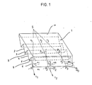
- la fig. 1 est une vue en perspective coupée d'un élément de panneau en matière transparente,
- la fig. 2 est une vue en coupe d'un élément tel que celui de la fig. 1, montrant un premier exemple d'actions sélectives de réflexion totale et de transmission exercées par les facettes,
- la fig. 3 est une vue en coupe analogue à la fig. 2, montrant un autre exemple d'actions sélectives exercées par les facettes,
- la fig. 4 est une vue en perspective coupée d'une face ou d'une facette exerçant une action sélective sur trois rayons situées dans des plans quelconques,
- la fig. 5 est une vue en coupe analogue à la fig. 2, montrant la projection, sur le plan perpendiculaire à la face,de l'action exercée par les facettes sur un rayon situé hors de ce plan,
- les fig. 6 et 7 sont des graphes représentant de façon schématique les performances de l'élément considéré dans les fig. 1 à 5, en termes de distribution angulaire,
- la fig. 8 est une vue en perspective coupée d'un élément correspondant à une autre forme d'exécution,
- la fig. 9 est un graphe représentant de façon schématique les performances de l'élément considéré dans la fig. 8, en termes de distribution angulaire,
- la fig. 10 est une vue schématique se référant à une utilisation d'un panneau en tant que paroi,
- la fig. 11 est une graphe illustrant de façon schématique les variations de l'angle d'incidence d'un faisceau parallèle provenant du soleil sur le panneau de la fig. 10, au cours des heures et des saisons,
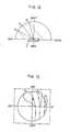
- la fig. 12 est une vue analogue à la fig. 10 montrant un panneau dont la position est proche de l'horizontale et inclinée ver l'ouest,
- la fig. 13 est un graphe analogue à celui de la fig. 11, et montrant les variations de l'angle d'incidence d'un faisceau parallèle provenant du soleil sur le panneau de la fig. 12, au cours des heures et des saisons.
- fig. 1 is a cut perspective view of a panel element made of transparent material,
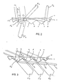
- fig. 2 is a sectional view of an element such as that of FIG. 1, showing a first example of selective actions of total reflection and transmission exerted by the facets,
- fig. 3 is a sectional view similar to FIG. 2, showing another example of selective actions exerted by the facets,
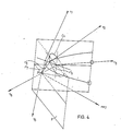
- fig. 4 is a perspective view cut from a face or a facet exerting a selective action on three rays located in any planes,
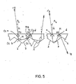
- fig. 5 is a sectional view similar to FIG. 2, showing the projection, on the plane perpendicular to the face, of the action exerted by the facets on a radius located outside this plane,
- fig. 6 and 7 are graphs schematically representing the performance of the element considered in FIGS. 1 to 5, in terms of angular distribution,
- fig. 8 is a cut perspective view of an element corresponding to another embodiment,
- fig. 9 is a graph schematically representing the performance of the element considered in FIG. 8, in terms of angular distribution,
- fig. 10 is a schematic view referring to a use of a panel as a wall,
- fig. 11 is a graph schematically illustrating the variations in the angle of incidence of a parallel beam coming from the sun on the panel of FIG. 10, during the hours and seasons,
- fig. 12 is a view similar to FIG. 10 showing a panel whose position is close to the horizontal and inclined towards the west,
- fig. 13 is a graph similar to that of FIG. 11, and showing the variations in the angle of incidence of a parallel beam coming from the sun on the panel of FIG. 12, during the hours and seasons.
Considérons maintenant un élément 1 (fig. 1) d'un panneau selon l'linvention. Il est consitué d'une plaque 1 en un matériau présentant un indice de réfraction n. Ce matériau peut être l'un des nombreux verres connus, ou le cas échéant une matière plastique transparente. Dans les exemples qui suivent, on considérera que l'indice de réfraction du matériau de l'élément est de l'ordre de n = 1,5. L'élément 1 comporte une face plane 10 qui constituera la face du panneau exposée à un rayonnement incident. L'autre face du panneau est une face fragmentée constituée d'une série de facettes 2, 3,4,5,6, etc. de formes rectangulaires jointes selon des arêtes 7, 8, etc. qui sont parallèles entre elles et parallèles à la face 10 de l'élément. De plus, on admettra dans cet exemple d'exécution que toutes les facettes 2,3,4,5,6 etc. sont de même forme et de même dimension, et qu'elles sont disposées symétriquement par rapport à des plans qui sont déterminés par des perpendiculaires à la face 10 et des parallèles aux arêtes 7,8 etc. Les différents prismes formés par chaque paire de facettes 2 et 3, 4 et 5, etc. sont donc des prismes symétriques, et pour la compréhension des explications qui vont suivre on admettra que dans une première variante l'angle au sommet de chaque prisme, c.à.d. l'angle dièdre entre les facettes 2 et 3 ou les facettes 4 et 5, est de l'ordre de 106°.Let us now consider an element 1 (fig. 1) of a panel according to the invention. It is made up of a
Considérons maintenant une source lumineuse S que l'on a représentée à la fig. 1 à une distance finie de la face 10, mais qui pourrait tout aussi bien être située à l'infini dans une direction quelconque comprise dans un plan perpendiculaire à la face 10 et parallèle aux arêtes longitudinales 7, 8 etc. Un rayon r1 issu de la source S et frappant la face 10 dans une direction perpendiculaire à cette face la traverse et frappe par exemple la facette 6 en un point P1. L'angle d'incidence alpha 1 de rayon r1 sur la facette 6 étant inférieur à l'angle critique du matériau, ce rayon est transmis à travers la facette 6 et ressort après réfraction dans la direction donnée par le rayon transmis t1. Considérons maintenant un rayon r2 issu de la même source, contenu également dans un plan perpendiculaire à la face 10 et parallèle aux arêtes 7, 8 etc. mais faisant avec la perpendiculaire à la face 10 un angle béta 2, de sorte qu'il subit une réfraction en traversant la face 10 et vient frapper la facette 6 en un point P2. Le rayon réfracté rʹ2 et la perpendiculaire à la facette 6 au point P2 déterminent un plan pi 2 dans lequel sera contenu le rayon transmis t2 issu au point P2 du rayon réfracté rʹ2. Le plan pi 2 est différent du plan perpendiculaire à la face 10 et contenant la source S. D'autre part, l'angle d'incidence alpha 2 du rayon réfracté rʹ2 avec la perpendiculaire à la facette 6 au point P2 est plus grand que l'angle alpha 1. On admettra cependant qu'il n'atteint toujours pas l'angle critique, de sorte que le rayon t2 est bien un rayon transmis. On comprend cependant que si l'on considère ensuite un rayon r3 ayant par rapport à la perpendiculaire à la face 10 une inclinaison plus grande que le rayon r2, mais également issu de la source S et contenu dans le même plan que les rayons r1 et r2, ce rayon r3 frappant avec un angle d'incidence béta 3 la face 10 pourra déterminer un rayon réfracté rʹ3 qui fera, au point P3 où il frappe la facette 6, aved la perpendiculaire en ce point à la facette 6 un angle alpha 3 qui sera supérieur à l'angle critique si l'angle d'incidence béta 3 est suffisamment grand, c.à.d. de l'ordre de 28° dans cet exemple. La facette 6 aura pour le rayon rʹ3 une action de réflexion totale et provoquera l'envoi d'un rayon réfléchi re3 qui finira par ressortir par la face 10, après un certain nombre des réflexions dans l'élément. Le plan pi 3 déterminé par les rayons rʹ3 et re3 et dans lequel est contenue également la perpendiculaire à la facette 6 au point P3 sera également un plan ayant une orientation différente de celle du plan contenant les rayons r1, r2 et r3.Let us now consider a light source S which has been represented in FIG. 1 at a finite distance from the
Bien entendu, ce qui a été expliqué ci-dessus à propos de rayons lumineux individuels r1, r2, r3 est également valable pour tout faisceau de rayons parallèles ayant l'une des directions définies par r1, r2 ou r3. D'autre part, on a considéré jusqu'à maintenant des faisceaux de rayons parallèles contenus dans des plans définis par la perpendiculaire à la face 10 et la parallèle aux arêtes longitudinales de l'élément. Dans cette forme d'exécution, cependant, si l'on considère un faiscau de rayons parallèles du type r1, on voit que, quelque soit le point d'incidence de ces rayons sur la face 10, ils pénétreront dans l'élément sans réfraction et frapperont n'importe laquelle des facettes 3,4,5,6 etc. selon un angle inférieur à l'angle critique, de sorte qu'ils ressortiront de l'élément sous forme de rayons transmis t1 déviés soit dans un sens, soit dans l'autre, suivant la direction selon laquelle les facettes qu'ils traversent sont inclinées. On comprend par contre que, dans d'autres formes d'exécution où l'angle que font les facettes avec la face 10 serait supérieur à l'angle critique du matériau, ces mêmes rayons r1, après avoir pénétré l'élément sans réfraction par la face 10, frapperaient n'importe quelle facettte 3,4,5,6 etc. selon un angle supérieur à l'angle critique, de sorte qu'ils seraient réfléchis par cette facette à l'intérieur de l'élément.Of course, what has been explained above with regard to individual light rays r1, r2, r3 is also valid for any beam of parallel rays having one of the directions defined by r1, r2 or r3. On the other hand, beams of parallel radii contained in planes defined by the perpendicular to the
Revenons à notre première forme d'exécution, et considérons maintenant un faisceau de rayons parallèles contenu dans un plan de coupe perpendiculaire aux arêtes longitudinales de l'élément 1, les rayons de ce faisceau faisant avec la perpendiculaire à la face 10 un angle béta 4. La fig. 2 montre que, lorsque l'angle béta 4 augmente, il atteint une valeur où les rayons du faiscau incident ne sont plus entièrement transmis, comme c'était le cas pour les rayons r1, mais où, après réfraction et formation des rayons rʹ4, ils tombent sur l'une des facettes 2,4,6, etc. par exemple la facette 2, la frappant en des points Pʹ4 où leur angle d'incidence alpha 4 par rapport à la perpendiculaire à la facette est supérieur à l'angle critique. On voit d'autre part que dans le cas représenté à la figure 2, ce fait donne lieu à deux phénomènes: d'une part une partie du faisceau frappant la facette 2 subit une première réflexion totale en direction de la face 10, pour être finalement renvoyé symétriquement à sa direction d'incidence après avoir été réfléchi par la facette 3, comme l'indique le faisceau F4, et d'autre part une partie du faisceau issu de la première réflexion totale frappe directement la facette 3 et subit une nouvelle réflexion totale, de sorte qu'il donne lieu au faisceau Fʹ4, qui est alors également renvoyé vers le côté source de l'élément 1. Quant au reste du rayonnement parallèle r4 qui, après réfraction par la face 10 et formation des rayons rʹ4, frappe la facette 3, il possède par rapport à cette facette un angle d'incidence alphaʹ4 qui est inférieur à l'angle critique, de sorte qu'il est réfracté vers le côté du panneau opposé à la source et donne lieu au faisceau Fʺ4.Let us return to our first embodiment, and now consider a beam of parallel rays contained in a section plane perpendicular to the longitudinal edges of
Ainsi, pour certaines valeurs de l'angle d'incidence, béta 4 sur la face 10, la fragmentation de la face opposée à la face 10 a pour effet une action de sélection du troisième type, c.à.d. un renvoi partiel et une transmission partielle du faisceau, en fonction du point précis d'incidence de chaque rayon sur la face 10.Thus, for certain values of the angle of incidence,
La fig. 3 montre un phénomène de transmission indirecte qui apparaît pour certaines valeurs des inclinaison des facettes, par exemple pour des angles inférieurs à 116° aux sommets de prismes symétriques lorsque l'indice de réfraction du matériau transparent est 1,5. Dans cette figure, comme dans les prédécentes, l'angle au sommet est de 106°.Fig. 3 shows a phenomenon of indirect transmission which appears for certain values of the inclination of the facets, for example for angles less than 116 ° to the vertices of symmetrical prisms when the refractive index of the transparent material is 1.5. In this figure, as in the previous ones, the angle at the top is 106 °.
Ainsi, si l'on considère des rayons incidents peu éloignés de l'horizontale, c.à.d. pour lesquels l'angle d'incidence béta 5 est proche de 90°, une partie du faisceau réfracté f5 vient frapper des facettes F3, F5, etc. et ressort de l'élément 1 après une nouvelle réfraction comme on le voit en fʹ5, à la fig. 3. Cependant, l'autre partie du faisceau incident réfractée à l'intérieur de l'élément 1 vient frapper les facettes F2, F4, F6, etc. et sur ces facettes subit une réflexion totale, qui le renvoie sur les facettes F3, F5, F7, etc. Celles-ci le transmettent et il ressort de l'élément 1 sous forme d'un faisceau dévié f6. On a pour ces faisceaux une transmission indirecte que l'on appellera d'ordre 1, puisqu'elle a lieu après une seule réflexion totale à l'intérieur de l'élément 1. L'ensemble du faisceau incident est donc transmis à travers l'élément 1.Thus, if we consider incident rays not far from the horizontal, i.e. for which the
Considérons maintenant l'ensemble des faisceaux dont les trajectoires incidentes se trouvent soit à l'intérieur, soit hors des deux plans de référence perpendiculaires à la face 10 mentionnés jusqu'ici, c.à.d. le plan parallèle aux arêtes longitudinales et le plan perpendiculaire à ces arêtes. Pour ressortir de l'élément, chacun de ces faisceaux devra, après avoir pénétré par la face 10 et avoir suivi une trajectoire plus ou moins longue à l'intérieur de cet élément, frapper soit une facette, soit la face 10, selon un angle inférieur à l'angle critique. Comme on considère maintenant les angles d'incidences quelconques de faisceaux provenant de toutes les directions de l'espace à trois dimensions, on doit tenir compte non plus simplement de l'angle critique du matériau sur la dite face ou facette dans l'un ou l'autre plan de référence, mais plus généralement du cône critique que forment les angles critiques dans l'ensemble des plans contenant la normale à cette facette. Le type de trajectoire que parcourt un rayon dépend de son angle d'incidence et le cas échéant de son point d'incidence sur l'élément. Par conséquent, à chaque type de trajectoire correspond un secteur angulaire d'incidences en provenance duquel les faisceaux sont transmis soit par la face, soit par la facette où aboutit ce type de trajectoire. Les limites séparant ces secteurs angulaires ont une courbure découlant de la forme même des cônes et des recouvrements découlant des recoupements partiels ou totaux des effets de ces cônes sur les trajectoires des faisceaux.Let us now consider all of the beams whose incident trajectories are either inside or outside the two reference planes perpendicular to the
Les fig. 4 et 5 montrent comment l'invention tire parti de ces cônes critiques et des limites qui leur correspondent. La fig. 4 montre en perspective coupée trois rayons frappant, de l'intérieur de l'élément, la face ou une facette, F1, au point P. Le rayon rʹ5, perpendiculiare à F, frappe F par l'intérieur du cône critique Cc, et est transmis par F sans réfraction en t5. Le rayon rʹ6, frappant F selon un angle d'incidence inférieur à l'angle critique, est transmis avec réfraction par F en t6. Le rayon rʹ7, frappant F selon un angle d'incidence supérieur à l'angle critique, est réfléchi par F sous la forme du rayon réfléchi re7.Figs. 4 and 5 show how the invention takes advantage of these critical cones and the limits which correspond to them. Fig. 4 shows in perspective cut three striking rays, from the interior of the element, the face or a facet, F1, at point P. The radius rʹ5, perpendicular to F, strikes F through the interior of the critical cone Cc, and is transmitted by F without refraction in t5. The radius rʹ6, striking F at an angle of incidence less than the critical angle, is transmitted with refraction by F at t6. The ray rʹ7, striking F at an angle of incidence greater than the critical angle, is reflected by F in the form of the reflected ray re7.
La fig. 5 représente un élément du même indice et de même configuration que les fig. 1, 2 et 3. Elle montre en coupe les cônes critiques Cca, Ccb, Ccc, Ccd entourant respectivement les normales N de la face 10, de la facette 2, de la facette 3 et de nouveau de la face 10. Elle montre en outre la projection sur le plan perpendiculaire aux arêtes, de deux trajectoires A et B possibles pour deux rayons r8 et rʹ8 appartenant à un même faisceau. Ces trajectoires sont situées hors des dits plans de référence et sont identiques à partir de la source jusqu'au point de réflexion sur la face 10 Pd. Lorsque le rayon r8 pénètre l'élément au point Pa et à l'intérieur du cône Cca, la composante de son angle de réfraction dans le plan perpendiculaire à l'élément et parallèle aux arêtes est inférieur à 42°, mais suffisamment proche de ce chiffre pour que le rayon r8 devenu re8 après avoir été réfléchi successivement par la facette 2 et la facette 3, atteigne la face 10 au point Pd par l'extérieur du cône Ccd, c.à.d. en faisant un angle de plus de 42° avec la normale à cette face. Ceci s'explique par le fait qu'en ce point Pd, la composante de la trajectoire dans l'autre plan de référence, c.à.d. le plan perpendiculaire aux arêtes est plus grande qu'au point Pa. Il y a réflexion du rayon qui poursuit son parcours, soit selon la trajectoire A, c.à.d. de façon symétrique au parcours de Pa à Pd, le rayon frappant d'abord la facette 4, soit selon la trajectoire B dans laquelle le rayon est réfléchi du point Pd vers la facette 3, et est transmis par celle-ci sous la forme du rayon t8. Nous nommerons ce type de transmission transmission indirecte d'ordre 2.Fig. 5 shows an element of the same index and the same configuration as FIGS. 1, 2 and 3. She shows in section the critical cones Cca, Ccb, Ccc, Ccd respectively surrounding the normals N of
Nous constatons que le point d'incidence du rayon r8 sur la face 10 et l'épaisseur de l'élément par rapport aux dimensions des facettes jouent un rôle déterminant quant à la proportion des rayons de même angle d'incidence qui suivent l'une ou l'autre trajectoire.We note that the point of incidence of the radius r8 on the
Notons d'une part, que si l'on fait varier de manière progressive l'angle d'incidence d'un faisceau de rayons parallèles, le passage d'un secteur à un autre, et donc d'un mode de sélection à un autre, se fait brusquement lorsque la trajectoire du faisceau franchit la limite virtuelle constituée par la surface de l'un ou l'autre cône critique, et que, d'autre part, les secteurs répartis en une distribution angulaire donnée, sont séparés par des courbes limites qui correspondent à des suites continues de valeurs de l'angle d'incidence sur la face 10, et par des points limites qui correspondent à des valeurs de l'angle d'incidence auxquelles des courbes limites se croisent. On peut donc tracer ces courbes et points limites dans un graphe représentant les angles d'incidence sur l'élément par leur azimuth et leur élévation.Let us note on the one hand, that if one varies in a progressive way the angle of incidence of a beam of parallel rays, the passage from one sector to another, and therefore from a mode of selection to a other, is done suddenly when the beam trajectory crosses the virtual limit constituted by the surface of one or the other critical cone, and that, on the other hand, the sectors distributed in a given angular distribution, are separated by limit curves which correspond to continuous sequences of values of the angle of incidence on the
La fig. 6 montre un tel graphe où l'axe x représente les incidences d'azimuths 0° et 180° contenues dans le plan de référence perpendiculaire à la face 10 et parallèle aux arêtes, où l'axe y représente les incidences d'azimuths 90° et 270° contenues dans le plan de référence perpendiculaire aux arêtes, et où les élévations forment des cercles concentriques, le cercle L représentant les élévations de 90° par rapport à la normale à la face 10. Le point central C correspond donc à l'angle d'incidence normal à la face 10, et dont l'azimuth et l'élévation sont égaux à 0°. Les courbes et points limites séparent dans l'angle solide de 180° du rayonnement incident les secteurs angulaires pour lesquels les actions de sélection sont de types différents. La fig. 6 montre l'ensemble des limites correspondant aux actions de sélection subies par les faisceaux atteignant d'abord les facettes 2, 4, 6 etc. inclinées dans une direction. Ces limites déterminent la distribution angulaire en sept secteurs qui correspond à la forme d'exécution particulière considérée dans cet exemple. Ces sept secteurs angulaires ont les propriétés suivantes: le secteur angulaire S1 englobe des faisceaux dont les rayons, tels r1 et r2 sont transmis à travers l'élément directement par la première facette 2, 4, 6, etc. qu'ils frappent; le secteur angulaire S2 englobe des faisceaux dont les rayons, après avoir été réfléchis par une facette 2, 4, 6, etc. sont transmis à travers le panneau par une facette 3, 5, 7, etc.; le secteur angulaire S3 englobe des faisceaux dont les rayons après avoir été réfléchis par une facette 2, 4, 6, etc. vers une facette 3, 5, 7, etc. sont renvoyés vers la face 10, puis retransmis par la face 10 du côté de la source; les secteurs angulaires S4 et S5 englobent des faisceaux dont les rayons peuvent, suivant l'endroit précis où ils frappent une facette 2, 4, 6, etc., soit être transmis à travers le panneau par une facette 3, 5, 7, etc. après avoir été réfléchis successivement par une première facette 2, 4, 6 etc. une facette 3, 5, 7, etc. et la face 10, soit être renvoyées vers la face 10, et transmis par celle-ci du côté de la source, après avoir été réfléchis successivement par une première facette 2, 4, 6, etc., la face 10, et une facette 3, 5, 7, etc., ou encore après avoir été réfléchis successivement par les facettes 2, 4, 6, etc. 3, 5, 7, etc. la face 10, et de nouveau les facettes 2, 4, 6, etc., 3, 5, 7, etc.; enfin, les secteurs angulaires S6 et S7 englobent des faisceaux dont les rayons sont finalement renvoyés du côté de la source, après une succession complexe de réflexions internes sur les facettes et la face 10.Fig. 6 shows such a graph where the x axis represents the incidences of 0 ° and 180 ° azimuths contained in the reference plane perpendicular to the
On peut établir un graphe du même genre pour représenter les courbes et points limites correspondant aux phénomènes subis par l'ensemble des faisceaux qui atteignent d'abord les facettes 3, 5, 7, etc. inclinées dans l'autre direction. Ce graphe sera exactement symétrique à celui présenté à la fig. 6, puisque les facettes 3, 5, 7, etc. sont symétriques aux facettes 2, 4, 6, etc.We can establish a graph of the same kind to represent the curves and limit points corresponding to the phenomena undergone by the set of beams which first reach
En combinant ces deux graphes, on obtient à la fig. 7 le graphe complet représentant la distribution angulaire déterminée par l'élément sur l'ensemble des faisceaux qui le frappent: le secteur angulaire S1 englobe des faisceaux dont tous les rayons sont transmis directement par la première facette 2, 4, 6, etc. ou 3, 5, 7, etc. frappée; les secteurs angulaires S2 et Sʹ2 englobent des faisceaux dont les rayons sont transmis soit par une facette 3, 5, 7, etc. après avoir été réfléchis par une facette 2, 4, 6, etc., soit par une facette 2, 4, 6, etc. après avoir été réfléchis par une facette 3, 5, 7, etc.; les secteurs S3, Sʹ3, S6, Sʹ6, S7 et Sʹ7 englobent des faisceaux dont une partie des rayons est finalement renvoyée par l'élément, après avoir été réfléchie deux fois ou plus par les facettes ou par les facettes et la face 10, et dont l'autre partie des rayons est directement transmise par la facette qu'ils frappent; les secteurs angulaires S8, S9, S10 et S11 englobent des faisceaux dont tous les rayons sont finalement renvoyés par l'élément, après avoir été réfléchis deux fois ou plus par les facettes ou par les facettes et la face 10; enfin, les secteurs angulaires S4 et S5 englobent des faisceaux dont une partie est finalement transmise, et l'autre partie finalement renvoyée, la proportion entre ces deux parties variant selon le rapport entre l'épaisseur de l'élément et la dimension des facettes.By combining these two graphs, we obtain in fig. 7 the complete graph representing the angular distribution determined by the element on the set of beams which strike it: the angular sector S1 includes beams of which all the rays are transmitted directly by the first facet 2, 4, 6, etc. or 3, 5, 7, etc. struck; the angular sectors S2 and Sʹ2 include beams whose rays are transmitted either by a facet 3, 5, 7, etc. after having been reflected by a facet 2, 4, 6, etc., or by a facet 2, 4, 6, etc. after having been reflected by a facet 3, 5, 7, etc .; sectors S3, Sʹ3, S6, Sʹ6, S7 and Sʹ7 include beams, part of the rays of which are finally returned by the element, after having been reflected twice or more by the facets or by the facets and the face 10, and whose other part of the rays is directly transmitted by the facet they strike; the angular sectors S8, S9, S10 and S11 include beams from which all the rays are finally returned by the element, after having been reflected twice or more by the facets or by the facets and the face 10; finally, the angular sectors S4 and S5 include beams, part of which is finally transmitted, and the other part finally returned, the proportion between these two parts varying according to the ratio between the thickness of the element and the dimension of the facets.
Le tracé des courbes limites et la dimension des secteurs dépend naturellemment des valeurs exactes des paramètres choisis. Ainsi, certaines courbes peuvent, au lieu de se croiser en deux points, ne plus se toucher que par un seul point, de sorte que l'amplitude du secteur englobé se réduit à une seule valeur de l'angle d'incidence, ou être totalement séparées. De même, certaines courbes déterminées par des facettes différentes peuvent se confondre. Dans d'autres formes d'exécution, on peut obtenir d'autres courbes ou d'autres déformations: par exemple, en cas de prisme axymétrique, les courbes sont déportées par rapport à l'axe x.The layout of the limit curves and the size of the sectors naturally depends on the exact values of the parameters chosen. Thus, certain curves may, instead of crossing at two points, only touch each other by a single point, so that the amplitude of the encompassed sector is reduced to a single value of the angle of incidence, or be totally separate. Similarly, certain curves determined by different facets can be confused. In other embodiments, other curves or other deformations can be obtained: for example, in the case of an axymmetric prism, the curves are offset relative to the x axis.
La forme d'exécution décrite jusqu'ici comportait une face plane et à l'opposé de cette face plane une face fragmentée composée d'un réseau de couples de facettes faisant entre elles un angle plus grand que 90°et formant des prismes symétriques à arêtes parallèles. Cependant, dans d'autres formes d'exécution, ces différents paramètres peuvent varier. L'angle que font les facettes entre elles peut aussi être égal ou inférieur à 90°. Les prismes peuvent ne pas être symétriques, leurs deux facettes n'ayant pas la même inclinaison par rapport à la face 10. Enfin, chaque prisme peut avoir plus de deux facettes.The embodiment described so far included a planar face and opposite this planar face a fragmented face composed of a network of pairs of facets forming an angle greater than 90 ° between them and forming symmetrical prisms with parallel edges. However, in other embodiments, these different parameters may vary. The angle that the facets make between them can also be equal to or less than 90 °. The prisms may not be symmetrical, their two facets not having the same inclination relative to the
Ainsi, la fig. 8 montre à titre d'exemple une deuxième forme d'exécution. On considère un élément 11 qui est également une plaque de matériau transparent, mais dont la structure diffère de celle de l'élément 1. Cet élément comporte toujours une face plane 20 qui est la face cachée dans la représentation en perspective de la fig. 8 et à l'opposé de cette face 20, une face fragmentée. Celle-ci comporte toutefois deux réseaux de facettes, formant des prismes complexes à quatre facettes. Le premier réseau est constitué par des rangées parallèles de couples de facettes dont les arêtes sont inclinées dans une direction par rapport à la face 20. Les facettes 21, 22, 23, 24, etc. forment une rangée de ce type, et les facettes 31, 32, 33,, 34, etc. une seconde rangée de ce type. Le second réseau est constitué par des rangées parallèles de couples de facettes dont les arêtes sont inclinées dans l'autre direction par rapport à la face 20. Pour simplifier, on considère ici le cas ou les arêtes des prismes des rangées du premier type font avec celles des prismes du second type un angle de 90° et ont une inclinaison égale, de 45° par rapport à la face 20. De même, dans chaque rangée, les facettes de chaque couple font entre elles un angle de 90°.Thus, fig. 8 shows by way of example a second embodiment. We consider an
Le graphe correspondant à cette forme d'exécution est très simple car, du fait que les facettes font entre elles des angles de 90° et que les arêtes font également entre elles des angles de 90°, toutes les limites importantes se superposent pour donner les quatre courbes représentées dans la fig. 9. Ces limites définissent sept secteurs angulaires: les secteurs S1 et Sʹ1 englobent des faisceaux dont tous les rayons sont directement ou indirectement transmis. Les secteurs S2, Sʹ2, Sʺ2 et S‴2 englobent des faisceaux dont une partie des rayons est transmise indirectement par une facette après avoir frappé une autre facette de la même rangée, et dont l'autre partie des rayons est renvoyée du côté de la source après avoir été réfléchie par soit deux, soit quatre facettes successivement; le secteur angulaire S3 englobe les faisceaux dont tous les rayons sont renvoyés du côté de la source après avoir été réfléchis successivement soit par deux, soit par quatre facettes. Certains phénomènes de sélection peu importants affectant certains rayons qui frappent les facettes près des sommets de prisme ne sont pas représentés sur la fig. 9.The graph corresponding to this embodiment is very simple because, because the facets make 90 ° angles between them and the edges also make 90 ° angles between them, all the important limits are superimposed to give the four curves shown in fig. 9. These limits define seven angular sectors: sectors S1 and Sʹ1 include beams of which all the rays are directly or indirectly transmitted. Sectors S2, Sʹ2, Sʺ2 and S ‴ 2 include beams, part of the rays of which are transmitted indirectly by a facet after striking another facet of the same row, and the other part of which is returned to the side of the source after having been reflected by either two or four facets successively; the angular sector S3 includes the beams, all the rays of which are returned to the side of the source after having been reflected successively either by two or by four facets. Certain minor selection phenomena affecting certain rays which strike the facets near the apexes of the prism are not shown in FIG. 9.
Dans un élément de ce genre, les différents paramètres constructifs, et par conséquent la distribution angulaire, peuvent également être modifiés dans de larges mesures. Ainsi, dès que les angles cessent d'être de 90°, les limites séparant les différents types de secteurs cessent de se superposer, et le graphe fait apparaître d'autres courbes et points limites. Bien entendu, on peut ici aussi imaginer d'autres répartitions de facettes dans une face fragmentée d'un élément selon l'invention. Il peut par exemple y avoir des prismes à trois facettes, cinq facettes, etc. Les prismes complexes peuvent également être asymétriques.In an element of this kind, the various constructive parameters, and therefore the angular distribution, can also be modified in large measures. Thus, as soon as the angles cease to be 90 °, the limits separating the different types of sectors cease to overlap, and the graph shows other curves and limit points. Of course, it is also possible here to imagine other distributions of facets in a fragmented face of an element according to the invention. For example, there may be three-faceted prisms, five facets, etc. Complex prisms can also be asymmetrical.
Cette forme d'exécution permet à l'élément de renvoyer de manière particulièrement efficace les rayonnements directs provenant par exemple du soleil lorsque l'élément étant orienté de manière à être perpendiculaire au soleil à son zénith, la trajectoire de celui-ci se traduit sur le graphe correspondant par le diamètre situé en position médiane du secteur S3.This embodiment allows the element to return in a particularly effective way direct radiation coming for example from the sun when the element being oriented so as to be perpendicular to the sun at its zenith, the trajectory of this one is translated on the corresponding graph by the diameter located in the middle position of sector S3.
Deux exemples d'exécution voisins permettront de montrer comment certaines modifications de la configuration de l'élément permettent de faire varier cette performance.Two neighboring execution examples will show how certain modifications to the configuration of the element allow this performance to be varied.
Un premier exemple de modification consiste à incliner de quelques degrés le plan dans lequel s'inscrivent les arêtes formées par les facettes 21 et 22, 31 et 32, de la figure 8 et ainsi de suite, de manière à ce que ce plan ne soit plus perpendiculaire à la face 20. Les courbes limites indiquées à la figure 9 se déplacent d'autant, donnant au secteur 3 une forme incurvée, asymétrique. La trajectoire, par exemple solaire, pour laquelle l'élément renvoie les rayons directs le plus efficacement se traduit alors sur le graphe par un arc traversant le secteur S3 dans sa longueur, l'élément n'étant plus tout à fait perpendiculaire à la source à son zénith.A first example of modification consists in inclining by a few degrees the plane in which the edges formed by the
Un deuxième exemple de modification consiste à aplanir sur la fig. 8 les rangées de facettes dont les arêtes sont orientés dans une direction, par exemple les rangées 21, 22, 23, 24, etc., 31, 32, 33, 34, etc. et ainsi de suite, tout en conservant la fragmentation en facettes des rangées dont les arêtes sont orientées dans l'autre direction. On obtient ainsi des prismes complexes à trois facettes. Le secteur S3 de la fig. 9 prend alors grossièrement la forme d'un triangle aux bords incurvés, permettant une variation très progressive de la performance de sélection en fonction des saisons.A second example of modification consists in flattening in FIG. 8 the rows of facets whose edges are oriented in one direction, for example the
Des panneaux constituant des parties d'enceinte dans une construction architecturale peuvent être constitués d'un ou de plusieurs éléments tels que les éléments selon l'invention. Dans le cas où l'on n'utilise qu'un seul élément, la face fragmentée peut être, dans certaines applications, exposée aux rayonnements aussi bien que la face plane, par exemple au cas où il y aurait deux sources de rayonnements, une de chaque côté du panneau.Panels constituting enclosure parts in an architectural construction may consist of one or more elements such as the elements according to the invention. In the case where only one element is used, the fragmented face can be, in certain applications, exposed to radiation as well as the planar face, for example in the case where there are two sources of radiation, a on each side of the panel.
D'autre part, au lieu que l'élément comporte une face plane et une face fragmentée, il peut également comporter deux faces fragmentées.On the other hand, instead of the element having a flat face and a fragmented face, it can also have two fragmented faces.
Une autre forme d'exécution intéressante des panneaux selon l'invention consiste à ajouter un élément complémentaire à l'élément principal qu'on a choisi d'utiliser.Another interesting embodiment of the panels according to the invention consists in adding a complementary element to the main element which we have chosen to use.
Un élément complémentaire est un élément comportant une face plane et une face fragmentée en facettes, les positions de ces faces étant inversées par rapport à celles qu'elles occupent dans un élément principal. Sa face fragmentée est juxtaposée facette à facette à celle d'un élément principal, les prismes des deux éléments ayant des angles identiques, et les rayonnements qui proviennent de cet élément principal le pénètrent par ses facettes. Il a surtout pour fonction d'ajouter à la face plane de l'élément principal une autre face plane parallèle. Il permet ainsi, d'une part de faire subir aux rayonnements traversant les deux éléments par une transmission directe une réfraction à leur sortie de ces éléments, complémentaire de celle subie en y pénétrant de manière que les rayons finalement transmis par le couple d'éléments en ressortent dans la même direction qu'à leur entrée dans celui-ci (afin que les déformations des images transmises, et les diffractions des rayonnements transmis, soient réduites au minimum), et d'autre part de faire subir à certains rayonnements traversant l'élément principal par des transmissions indirectes une réflexion totale supplémentaire, de manière à les renvoyer, en leur faisant retraverser l'élément principal, vers leur milieu source, augmentant ainsi la proportion des rayonnements finalement renvoyés par le panneau.An additional element is an element comprising a flat face and a face fragmented into facets, the positions of these faces being reversed with respect to those which they occupy in a main element. Its fragmented face is juxtaposed facet to facet to that of a main element, the prisms of the two elements having identical angles, and the radiations which come from this main element penetrate it by its facets. Its main function is to add to the flat face of the main element another parallel flat face. It thus allows, on the one hand to subject the radiation passing through the two elements by direct transmission to a refraction at their exit from these elements, complementary to that undergone by penetrating therein so that the rays finally transmitted by the pair of elements emerge in the same direction as when they entered it (so that the distortions of the transmitted images, and the diffractions of the transmitted radiation, are reduced to a minimum), and on the other hand to subject certain radiation passing through the 'principal element by indirect transmissions an additional total reflection, so as to return them, by making them cross again the principal element, towards their source medium, thus increasing the proportion of the radiations finally returned by the panel.
Cette deuxième action de l'élément complémentaire permet d'augmenter le nombre des valeurs utiles des angles aux sommets des prismes de l'élément principal, en incluant des angles plus fermés, l'éventail pouvant dès lors aller théoriquement (si ce prisme est symétrique et pour un angle critique de 42°) de 142° à 12° (valeur à partir de laquelle il n'y a plus de transmissions directes dans un prisme symétrique). Dans la pratique, on choisira des valeurs suffisamment différentes de 142° et de 12° pour qu'il y ait suffisamment de faisceaux incidents appartenant aux secteurs de chacun des types désirés.This second action of the complementary element makes it possible to increase the number of useful values of the angles at the vertices of the prisms of the element main, including more closed angles, the range being able to go theoretically (if this prism is symmetrical and for a critical angle of 42 °) from 142 ° to 12 ° (value from which there is no longer direct transmissions in a symmetrical prism). In practice, sufficiently different values of 142 ° and 12 ° will be chosen so that there are enough incident beams belonging to the sectors of each of the desired types.
L'interstice entre les faces fragmentées des deux éléments est d'épaisseur constante. Cependant, on pourra par un interstice suffisamment large, obtenir certains changements de trajectoires.The gap between the fragmented faces of the two elements is of constant thickness. However, it will be possible by a sufficiently large interstice to obtain certain changes in trajectories.
Cet interstice sera occupé par de l'air ou, le cas échéant, dans certaines constructions, pourra être maintenu vide. Il pourrait aussi, en variante, être occupé par un milieu transparent ayant un indice de réfraction suffisamment différent de l'indice du matériau constituant les éléments pour obtenir les phénomènes de réflexion totale désirés.This gap will be occupied by air or, if necessary, in certain constructions, may be kept empty. It could also, as a variant, be occupied by a transparent medium having a refractive index sufficiently different from the index of the material constituting the elements to obtain the desired total reflection phenomena.
Il faut souligner le fait que l'élément principal et l'élément complémentaire étant disposés symétriquement l'un à l'autre, ils peuvent échanger leurs rôles pour des rayonnement voyageant en sens inverse, c.à.d. provenant du milieu protégé.It should be emphasized that the main element and the complementary element being arranged symmetrically to each other, they can exchange their roles for radiation traveling in opposite directions, i.e. from the protected environment.
Des éléments tels que décrits précédemment semblables ou complémentaires, identiques ou différents peuvent être superposés pour constituer des panneaux selon l'invention. On peut aussi prévoir l'utilisation de plusieurs éléments placés bord à bord de façon à constituer une paroi ou une baie vitrée. Toutefois, dans certains cas, on peut également avoir intérêt à prévoir des parties de cloisons ou des parties d'enceintes constituées de plusieurs éléments selon l'invention placés bord à bord, sans toutefois être dans le même plan, les valeurs des angles que font entre eux de tels éléments devant alors être suffisamment différentes de 180° pour que l'interaction optique entre ces éléments modifie la distribution angulaire globale que le panneau détermine dans l'angle solide de 180° du rayonnement incident, tout en maintenant un équilibre suffisant entre les divers types de secteurs de cette distribution angulaire.Elements as described previously similar or complementary, identical or different can be superimposed to form panels according to the invention. One can also provide for the use of several elements placed edge to edge so as to constitute a wall or a bay window. However, in certain cases, it may also be advantageous to provide parts of partitions or parts of enclosures made up of several elements according to the invention placed side by side, without however being in the same plane, the values of the angles which such elements make between them must then be sufficiently different from 180 ° so that the optical interaction between these elements modifies the overall angular distribution that the panel determines in the 180 ° solid angle of the incident radiation, while maintaining a sufficient balance between the various types of sectors of this angular distribution.
On comprend donc que l'invention permet de faire varier la distribution angulaire des panneaux également en fonction de paramètres autres que ceux propres au prisme lui-même. D'une part, le voisinage des nombreux prismes répétitifs formant l'élément, et d'autre part le rapport entre la profondeur des reliefs et l'épaisser de l'élément (paramètre déterminant l'importance des passages internes entre les prismes), modifient à leur tour le répertoire des trajectoires. Certains rayonnements peuvent en effet, selon leur angle d'incidence, passer d'un prisme donné à un prisme voisin, dans certains cas par l'intérieur du matériau transparent (par réflexion totale sur les faces 10 ou 20), dans d'autres cas par l'extérieur du matériau transparent (par transmission par une facette d'un prisme, puis récupération par une facette d'un autre prisme). Dans ces deux cas, il faut considérer des trajectoires, parcourant et regroupant plus d'un prisme.It is therefore understood that the invention makes it possible to vary the angular distribution of the panels also as a function of parameters other than those specific to the prism itself. On the one hand, the proximity of the many repetitive prisms forming the element, and on the other hand the relationship between the depth of the reliefs and the thickness of the element (parameter determining the importance of the internal passages between the prisms), in turn modify the repertoire of trajectories. Certain radiations can indeed, according to their angle of incidence, pass from a given prism to a neighboring prism, in certain cases by the interior of the transparent material (by total reflection on the
Il faut noter également que dans certaines formes d'exécution, le prolongement de certaines facettes sous forme de fentes à l'intérieur de l'élément permet d'augmenter utilement la surface de ces facettes, comme en particulier dans le cas des facettes les plus étroites des prismes asymétriques.It should also be noted that in certain embodiments, the extension of certain facets in the form of slots inside the element makes it possible to usefully increase the surface of these facets, as in particular in the case of the most narrow asymmetric prisms.
L'invention permet également de faire varier la distribution angulaire en fonction de certaines combinaisons d'éléments. Si l'on rapproche deux éléments ou plus, soit en les juxtaposant par leurs faces (faces fragmentées et/ou faces planes) soit en les joignant par leurs bords selon des angles suffisamment différents de 180°, le répertoire des trajectoires est encore modifié, du fait que les rayonnements transmis par un élément sont directement reçus, puis sélectionnés, par tout autre élément juxtaposé à lui face à face, et du fait que certains des rayonnements transmis ou renvoyés par un élément sont reçus, puis sélectionnés, par tout élément joint à lui bord à bord selon un angle convenable. Il faut, dans ces deux cas, considérer des trajectoires, parcourant et regroupant plus d'un élément. Un cas particulier de combinaison d'éléments est celui d'un panneau comportant quatre faces fragmentées emboîtées deux à deux et où les plans non parallèles au panneau et parallèles entre eux dans lesquels sont contenues les dites arêtes forment deux familles de plans, contenant respectivement les arêtes de l'un des interfaces et celles de l'autre, et se croisent selon un angle différent de 0°.The invention also makes it possible to vary the angular distribution as a function of certain combinations of elements. If we bring two or more elements together, either by juxtaposing them by their faces (fragmented faces and / or planar faces) or by joining them by their edges at angles sufficiently different from 180 °, the repertoire of trajectories is further modified, the fact that the radiation transmitted by an element is directly received, then selected, by any other element juxtaposed to it face to face, and the fact that some of the radiation transmitted or returned by an element are received, then selected, by any attached element side by side at a suitable angle. In these two cases, trajectories must be considered, covering and grouping more than one element. A particular case of combination of elements is that of a panel comprising four fragmented faces nested in pairs and where the planes not parallel to the panel and parallel to each other in which the said edges are contained form two families of planes, containing respectively the edges of one of the interfaces and those of the other, and intersect at an angle different from 0 °.
Il est, enfin, possible d'obtenir une distribution angulaire combinée en mettant à profit les interactions pouvant apparaître entre plusieurs panneaux, les uns recevant les rayonnements transmis ou renvoyés par les autres (réciproquement ou non), soit de manière à obtenir une meilleure performance sélective d'ensemble, soit de manière à dévier ou conduire certains rayonnements selon des trajectoires et sur des distances dépassant l'ordre de grandeur d'un panneau.It is, finally, possible to obtain a combined angular distribution by taking advantage of the interactions that may appear between several panels, some receiving the radiation transmitted or returned by the others (reciprocally or not), either so as to obtain a better performance. selective overall, either so as to deflect or conduct certain radiation along trajectories and over distances exceeding the order of magnitude of a panel.
De manière générale, les paramètres de configuration des éléments sont déterminés de telle sorte que la distribution angulaire de l'angle solide de 180° du rayonnement incident qui correspond au panneau soit positionnée par rapport au cycle complet de la source (c.à.d. par exemple à la portion du dit angle solide que parcourt le soleil au cours des heures et des saisons) de manière à s'y superposer, de la manière exacte nécessaire, dans chaque cas, à l'accomplissement des fonctions du panneau.Generally, the configuration parameters of the elements are determined in such a way that the angular distribution of the solid angle of 180 ° of the incident radiation which corresponds to the panel is positioned with respect to the complete cycle of the source (i.e. for example to the portion of said solid angle traversed by the sun during the hours and seasons) so as to be superimposed thereon, in the exact manner necessary, in each case, for the performance of the functions of the panel.
Plus précisément, en cas d'éléments à prismes simples, les paramètres doivent avoir des valeurs déterminées en sorte que, pour chacun de ces prismes pris individuellement, de tous les faisceaux provenant de l'angle solide de 180° du rayonnement incident qui pénètrent ce prisme par la face plane et qui sont finalement transmis entièrement ou en partie par l'élément auquel appartient ce prisme, certains le sont soit par des transmissions indirectes d'ordre 1 et directes, soit par des transmissions indirectes d'ordre 2 et directes, soit encore par les trois à la fois. Il en résulte que, par exemple, pour un prisme simple symétrique, si l'angle critique est égal à 42° (chiffre typique pour un verre de construction), les valeurs utiles limites de l'angle que font les deux facettes entre elles se situent entre 142° en 12°. En cas d'éléments à prismes complexes (plus de deux facettes par prisme) du fait que chaque couple de facettes se comporte, avec la face plane de celui-ci, comme un prisme "simple" (à la différence que son arête n'est pas parallèle à la face plane), il existe, pour chaque prisme complexe pris individuellement, plus d'un couple de courbes par types de trajectoires. Il en résulte que l'action de l'élément dépend de la combinaison particulière de couples de facettes que réalise le prisme complexe, plus que des valeurs propres à l'un ou l'autre de ces couples.More precisely, in the case of elements with simple prisms, the parameters must have values determined so that, for each of these prisms taken individually, of all the beams coming from the solid angle of 180 ° of the incident radiation which penetrate this prism by the flat face and which are ultimately transmitted entirely or in part by the element to which this prism belongs, some are either by indirect transmissions of
Les panneaux selon l'invention seront utilisés par la construction d'enceintes dans diverses réalisations architecturales. La grande variété des performances de ces panneaux dûe aux différentes formes d'exécution et au grand choix des paramètres pour chacune d'elles permettra de les implanter de diverses manières, horizontalement, en pente, ou verticalement, de les orienter également diversement par rapport au parcours du soleil ou à la source, soit qu'ils protègent un local situé à l'intérieur d'un bâtiment ou un espace non-clos.The panels according to the invention will be used by the construction of enclosures in various architectural achievements. The wide variety of performance of these panels due to the different forms of execution and the large choice of parameters for each of them will allow them to be installed in various ways, horizontally, sloping, or vertically, to orient them also differently in relation to the route from the sun or at the source, either that they protect a room located inside a building or an open space.
Ainsi, les fig.10 et 11 donnent un exemple se rapportant au cas d'un panneau P qui est implanté dans une enceinte en étant orienté face au sud dans une position légèrement inclinée par rapport à la verticale. A la fig. 10 on a représenté dans un schéma le panneau P et les directions Se et So et Sh du soleil au midi, respectivement au solstice d'été, à l'équinoxe et au solstice d'hiver. La direction de la perpendiculaire au panneau P étant indiquée par la droite p, on a noté à la fig. 10 les angles entre les directions de la perpendiculaire et des trois positions solaires par les indications bétae, bétao, et bétah. Dans un graphe permettant de repérer les orientations d'une source par rapport à la perpendiculaire au panneau, tel qu'il est représenté à la fig. 11, on voit qu'une ligne horizontale H représent la direction de l'horizon repérée par rapport à la perpendiculaire au panneau et indique donc par l'ordonnée pi l'inclinaison de cette perpendiculaire par rapport à l'horizontale. Les trajectoires journalières du soleil au trois dates de l'année indiquées plus haut peuvent être facilement reportés sur ce graphe comme on le voit à la fig. 11 de sorte que, si l'on superpose au graphe de la fig. 11 le graphe donnant les performances du panneau P d'une façon analogue à ce que l'on a indiqué à propos des fig. 7 et 9, on obtient immédiatement une image de la façon dont le panneau réagit à l'impact des rayons solaires au cours d'une journée et au cours de l'année. Concernant les panneaux utilisés comme toitures, les fig. 12 et 13 montrent les performances obtenues dans le cas d'une utilisation d'un panneau P en tant qu'élément de toiture dont la perpendiculaire est contenue dans un plan vertical orienté est-ouest et est inclinée vers l'ouest. Les directions du soleil aux trois dates de l'année figurant déjà à la fig. 10 sont à nouveau représentées à la fig. 12 et les trajectoires correspondantes du soleil repérées par rapport à la perpendiculaire au panneau dans un graphe du même genre que celui de la fig. 11 sont représentés à la fig. 13. On se rend compte facilement des multiples possibilités qu'ouvre l'utilisation des éléments du type de ceux décrits pour réaliser des panneaux de toitures ou des panneaux de parois permettant de tirer parti de la façon la meilleure possible des conditions extérieures pour régler la pénétration de lumière et de chaleur dans un espace protégé par un ou plusieurs d'entre eux. En climat chaud, de même qu'en climat froid, on obtient un avantage thermique extrêmement marqué en ayant la possibilité de laisser le rayonnement thermique pénétrer dans l'espace protégé à l'époque de l'année où les conditions climatiques l'exigent, c.à.d. en hiver, alors qu'au moment de l'année où l'élévation et l'azimuth du soleil atteignent des valeurs qui correspondent au maximum d'ensoleillement, les rayonnements pa rallèles provenant du soleil peuvent être compris dans un secteur pour lequel la performance du panneau est le renvoi des rayonnements du côté de la source. A ce propos, une possibilité intéressante consiste dans le fait que les panneaux peuvent être configurés de manière à réorienter certains faisceaux incidents directement en direction de la source, ce qui peut être utile par exemple pour éviter des effets de réflexion des rayons solaires vers le sol au pied des bâtiments.Thus, fig.10 and 11 give an example relating to the case of a panel P which is located in an enclosure while being oriented facing south in a position slightly inclined relative to the vertical. In fig. 10 there is shown in a diagram the panel P and the directions Se and So and Sh from sun to noon, respectively to the summer solstice, to the equinox and to the winter solstice. The direction of the perpendicular to the panel P being indicated by the straight line p, we have noted in fig. 10 the angles between the directions of the perpendicular and the three solar positions by the indications beta e , beta o , and beta h . In a graph allowing to locate the orientations of a source compared to the perpendicular to the panel, such as it is represented in fig. 11, we see that a horizontal line H represents the direction of the horizon identified with respect to the perpendicular to the panel and therefore indicates by the ordinate pi the inclination of this perpendicular with respect to the horizontal. The daily trajectories of the sun at three dates of the year indicated above can be easily plotted on this graph as seen in fig. 11 so that, if one superimposes the graph of FIG. 11 the graph giving the performance of the panel P in a manner analogous to that which has been indicated in connection with FIGS. 7 and 9, an image is immediately obtained of how the panel reacts to the impact of the sun's rays during a day and during the year. Regarding the panels used as roofs, figs. 12 and 13 show the performance obtained when using a panel P as a roof element whose perpendicular is contained in a vertical plane oriented east-west and is inclined towards the west. The directions of the sun at the three dates of the year already shown in fig. 10 are again shown in FIG. 12 and the corresponding paths of the sun identified with respect to the perpendicular to the panel in a graph of the same kind as that of FIG. 11 are shown in FIG. 13. It is easy to see the multiple possibilities opened up by the use of elements of the type described for making roofing panels or wall panels making it possible to take advantage of the external conditions in the best possible way. penetration of light and heat into a space protected by one or more of them. In hot climate, as in cold climate, one obtains an extremely marked thermal advantage by having the possibility of letting thermal radiation penetrate in the protected space at the time of the year when the climatic conditions require it, i.e. in winter, when at the time of the year when the elevation and the azimuth of the sun reach values which correspond to the maximum of sunshine, the radiation pa Rallels coming from the sun can be understood in a sector for which the performance of the panel is the return of radiation on the source side. In this regard, an interesting possibility consists in the fact that the panels can be configured so as to redirect certain incident beams directly towards the source, which can be useful for example to avoid effects of reflection of solar rays towards the ground at the foot of the buildings.
En ce qui concerne l'utilisation en toitures, le panneau décrit apporte une solution élégante et peu onéreuse au problème des l'éclairage zénithal des surfaces industrielles, commerciales, culturelles ou autres qui demandent un apport lumineux dont la stabilité, l'homogénéité et la répartition soient contrôlées. Il permet la réalisation de couvertures entièrement transparentes contrôlant le transfert des faisceaux incidents en fonction à la fois de leur apport en éclairement et en échauffement. Cette solution peut remplacer progressivement l'utilisation de couvertures en sheds, solution dont on sait qu'elle est encombrante et structurellement compliquée, tout en ayant des performances qui n'ont jamais été entièrement satisfaisantes.With regard to the use on roofs, the panel described provides an elegant and inexpensive solution to the problem of overhead lighting of industrial, commercial, cultural or other surfaces which require a light supply whose stability, homogeneity and distribution are controlled. It allows the creation of entirely transparent covers controlling the transfer of incident beams according to both their contribution in lighting and in heating. This solution can gradually replace the use of shed blankets, a solution which is known to be bulky and structurally complicated, while having performances which have never been entirely satisfactory.
Les éléments et panneaux décrits peuvent également être utilisés comme couvertures de plans opaques et cela soit en façades, soit en toitures. Ainsi, de nombreux plans opaques, tels que allèges, façades-rideaux gagnent à être recouverts du panneau décrit. En effet, lors des périodes chaudes de l'année, et/ou de la journée, ces plans peuvent être soumis à un échauffement intense qui souvent est nuisible à la structure elle-même et qui de plus se répercute de façon défavorable à l'intérieur du bâtiment. Le revêtement de structures de ce genre par un ou plusieurs éléments tels que décrits plus haut permet de maximiser l'échauffement des plans en période froide et de le minimiser en période chaude, donc de réduire les frais d'isolation et de climatisation du bâtiment. Des façades entièrement en verre peuvent dès lors être prévues et cela avec des avantages tant climatiques qu'ésthétiques et de coût.The elements and panels described can also be used as covers for opaque planes, either in facades or in roofs. Thus, many opaque planes, such as lighters, curtain facades benefit from being covered with the panel described. Indeed, during hot periods of the year, and / or the day, these plans can be subjected to an intense heating which often is harmful to the structure itself and which moreover has an unfavorable effect on the interior of the building. The coating structures of this kind with one or more elements as described above makes it possible to maximize the heating of the plans in cold periods and to minimize it in hot periods, therefore to reduce the costs of insulation and air conditioning of the building. Facades made entirely of glass can therefore be provided, with both climatic, aesthetic and cost advantages.
De façon générale, on sait que l'on cherche toujours plus à protéger certains espaces privés ou publics par des parois et/ou des couvertures transparentes. Toutefois, ces réalisations se sont, jusqu'à maintenant soit heurtées à l'effet de serre qui est insupportable en période chaude et exige souvent des installations et des structures de climatisation coûteuses et entraînant des frais de service importants, et une perte de luminosité et en hiver de chaleur. Les panneaux décrits permettent d'apporter à ce problème une solution passive ne nécessitant ni stores, ni climatisation active. L'espace protégé par des panneaux de ce genre peut bénéficier intégralement en période froide de l'effet de serre tout en l'évitant entièrement en période chaude et cela sans modification de l'installation entre les deux périodes.In general, we know that we are always trying to protect certain private or public spaces with transparent walls and / or covers. However, these achievements have, until now, come up against the greenhouse effect which is unbearable in hot weather and often requires costly air conditioning installations and structures and entailing significant service costs, and a loss of brightness and in winter heat. The panels described provide a passive solution to this problem, requiring neither blinds nor active air conditioning. The space protected by panels of this kind can fully benefit in the cold period from the greenhouse effect while avoiding it entirely in hot periods and this without modifying the installation between the two periods.
Les éléments et panneaux décrits seront donc utiles dans la réalisation d'atriums, de mails couverts ou d'autres espaces publics ou privés à parois et couvertures transparentes.The elements and panels described will therefore be useful in the creation of atria, covered malls or other public or private spaces with transparent walls and covers.
Finalement, ils pourront bien entendu trouver aussi une application dans les constructions de serres.Finally, they can of course also find an application in greenhouse construction.
Dans les cas où on cherche à utiliser l'effet de serre au maximum et non pas à s'en préserver, les panneaux décrits peuvent également être intéressants par le fait qu'ils peuvent fonctionner dans les deux sens. Ainsi, un espace protégé par des parois transparentes peut être configuré grâce aux panneaux décrits de manière à retenir à l'intérieur de cet espace des rayonnements qui tendraient à s'en échapper, qu'il s'agisse de rayonnements solaires qui sans cela traverseraient la serre de part en part ou qu'il s'agisse de rayonnements émanant en période froide ou nocturne d'une source artificielle située dans l'espace protégé. De plus, les parois transparentes peuvent être conçues de façon que les rayonnements provenant de l'extérieur soient utilisés également dans les conditions climatiques et lumineuses les meilleures.In the cases where one seeks to use the greenhouse effect to the maximum and not to preserve it, the panels described can also be interesting by the fact that they can function in both meaning. Thus, a space protected by transparent walls can be configured thanks to the panels described so as to retain inside this space radiation which would tend to escape, whether it is solar radiation which would otherwise pass through the greenhouse from side to side or whether it is radiation emanating in a cold or nocturnal period from an artificial source located in the protected space. In addition, the transparent walls can be designed so that radiation from the outside is also used in the best climatic and light conditions.
Claims (12)
Priority Applications (1)
| Application Number | Priority Date | Filing Date | Title |
|---|---|---|---|
| EP86810048A EP0230854A1 (en) | 1986-01-27 | 1986-01-27 | Transparent panel forming a part of a room in an architectural construction |
Applications Claiming Priority (1)
| Application Number | Priority Date | Filing Date | Title |
|---|---|---|---|
| EP86810048A EP0230854A1 (en) | 1986-01-27 | 1986-01-27 | Transparent panel forming a part of a room in an architectural construction |
Publications (1)
| Publication Number | Publication Date |
|---|---|
| EP0230854A1 true EP0230854A1 (en) | 1987-08-05 |
Family
ID=8196449
Family Applications (1)
| Application Number | Title | Priority Date | Filing Date |
|---|---|---|---|
| EP86810048A Withdrawn EP0230854A1 (en) | 1986-01-27 | 1986-01-27 | Transparent panel forming a part of a room in an architectural construction |
Country Status (1)
| Country | Link |
|---|---|
| EP (1) | EP0230854A1 (en) |
Citations (4)
| Publication number | Priority date | Publication date | Assignee | Title |
|---|---|---|---|---|
| US2993409A (en) * | 1957-01-02 | 1961-07-25 | Owens Illinois Glass Co | Skylights |
| US3185034A (en) * | 1961-09-26 | 1965-05-25 | Mississippi Glass Co | Patterned glass |
| FR1442592A (en) * | 1964-05-25 | 1966-06-17 | Panel allowing light to pass through | |
| US4519675A (en) * | 1982-04-18 | 1985-05-28 | Bar Yonah Yitzchak | Selectively light transmitting panel |
-
1986
- 1986-01-27 EP EP86810048A patent/EP0230854A1/en not_active Withdrawn
Patent Citations (4)
| Publication number | Priority date | Publication date | Assignee | Title |
|---|---|---|---|---|
| US2993409A (en) * | 1957-01-02 | 1961-07-25 | Owens Illinois Glass Co | Skylights |
| US3185034A (en) * | 1961-09-26 | 1965-05-25 | Mississippi Glass Co | Patterned glass |
| FR1442592A (en) * | 1964-05-25 | 1966-06-17 | Panel allowing light to pass through | |
| US4519675A (en) * | 1982-04-18 | 1985-05-28 | Bar Yonah Yitzchak | Selectively light transmitting panel |
Similar Documents
| Publication | Publication Date | Title |
|---|---|---|
| EP2132786B1 (en) | Flat light concentrator of small thickness | |
| US4411493A (en) | Seasonal control skylight glazing panel with passive solar energy switching | |
| EP1982226A1 (en) | Optical system for displaying an image on the surface of a solar panel | |
| FR2463254A1 (en) | METHOD AND DEVICE FOR STOPPING OR LEFTING SOLAR LIGHT ACCORDING TO THE SEASON | |
| EP0004242A1 (en) | Solar radiation concentrator | |
| EP1866495B1 (en) | Brick or block-shaped building element and the assembly thereof | |
| JP2004519700A (en) | Polygon reflection type light guide film | |
| EP3325734B1 (en) | Inclined and fixed blind system | |
| EP0230854A1 (en) | Transparent panel forming a part of a room in an architectural construction | |
| FR3001213A1 (en) | GLASS SUBSTRATE TEXTURE FOR BUILDING | |
| FR2981681A1 (en) | Directional screen element e.g. blind, for use in screen element assembly forming glass portion of building envelope, has faces extending along different directions that are angularly shifted relative to rotation axis from acute angle | |
| EP0878661B1 (en) | Glass element for space illumination with daylight | |
| CH650546A5 (en) | PANEL FOR CONSTRUCTION ELEMENT. | |
| EP2753884B1 (en) | Thermal device with light guide | |
| BE569237A (en) | ||
| EP0964112B1 (en) | Transparent panel for building improving the natural brightness inside the building | |
| EP1496320A1 (en) | Flat solar panel with small thickness | |
| FR2478281A1 (en) | Solar oven with selective radiation absorption - has internal shield preventing escape of internally reflected radiation | |
| EP3480943B1 (en) | System for collecting solar energy | |
| FR3067822B1 (en) | PHOTOVOLTAIC GLAZING WHOSE TRANSPARENCY TO CLOSE INFRA-RED ADAPTS TO THE HEIGHT OF THE SUN | |
| WO2023036866A1 (en) | Building with heliodynamic architecture | |
| EP4128365A1 (en) | Bipv comprising a transparent or translucent element with diffuse reflection | |
| FR3045597A1 (en) | GLAZING WHOSE TRANSPARENCY TO INFRA-RED ADAPTS TO THE HEIGHT OF THE SUN | |
| BE508972A (en) | ||
| FR2892833A1 (en) | STATIC DISPLAY SCREEN WITH VARIABLE APPEARANCE PATTERN |
Legal Events
| Date | Code | Title | Description |
|---|---|---|---|
| PUAI | Public reference made under article 153(3) epc to a published international application that has entered the european phase |
Free format text: ORIGINAL CODE: 0009012 |
|
| AK | Designated contracting states |
Kind code of ref document: A1 Designated state(s): BE CH DE FR GB IT LI SE |
|
| STAA | Information on the status of an ep patent application or granted ep patent |
Free format text: STATUS: THE APPLICATION IS DEEMED TO BE WITHDRAWN |
|
| 18D | Application deemed to be withdrawn |
Effective date: 19880206 |