EP0963147A2 - Klammeranordnung für Signalübertragungskabel zur Erdung der geflechten Abschirmung - Google Patents
Klammeranordnung für Signalübertragungskabel zur Erdung der geflechten Abschirmung Download PDFInfo
- Publication number
- EP0963147A2 EP0963147A2 EP99110692A EP99110692A EP0963147A2 EP 0963147 A2 EP0963147 A2 EP 0963147A2 EP 99110692 A EP99110692 A EP 99110692A EP 99110692 A EP99110692 A EP 99110692A EP 0963147 A2 EP0963147 A2 EP 0963147A2
- Authority
- EP
- European Patent Office
- Prior art keywords
- holes
- cables
- plates
- metallic
- aligned
- Prior art date
- Legal status (The legal status is an assumption and is not a legal conclusion. Google has not performed a legal analysis and makes no representation as to the accuracy of the status listed.)
- Granted
Links
- 238000013519 translation Methods 0.000 claims abstract description 7
- 238000005253 cladding Methods 0.000 claims abstract description 5
- 238000009954 braiding Methods 0.000 claims description 15
- 238000010008 shearing Methods 0.000 abstract description 5
- 238000002955 isolation Methods 0.000 abstract description 2
- 239000004020 conductor Substances 0.000 description 10
- 230000006835 compression Effects 0.000 description 5
- 238000007906 compression Methods 0.000 description 5
- 208000032365 Electromagnetic interference Diseases 0.000 description 3
- 230000005540 biological transmission Effects 0.000 description 2
- 230000000903 blocking effect Effects 0.000 description 2
- 238000010276 construction Methods 0.000 description 2
- 230000008878 coupling Effects 0.000 description 2
- 238000010168 coupling process Methods 0.000 description 2
- 238000005859 coupling reaction Methods 0.000 description 2
- 229920001971 elastomer Polymers 0.000 description 2
- 239000000806 elastomer Substances 0.000 description 2
- 230000005670 electromagnetic radiation Effects 0.000 description 2
- 239000006260 foam Substances 0.000 description 2
- 239000000463 material Substances 0.000 description 2
- 238000000034 method Methods 0.000 description 2
- 239000000203 mixture Substances 0.000 description 2
- RYGMFSIKBFXOCR-UHFFFAOYSA-N Copper Chemical compound [Cu] RYGMFSIKBFXOCR-UHFFFAOYSA-N 0.000 description 1
- RTAQQCXQSZGOHL-UHFFFAOYSA-N Titanium Chemical compound [Ti] RTAQQCXQSZGOHL-UHFFFAOYSA-N 0.000 description 1
- 238000007792 addition Methods 0.000 description 1
- 229910052802 copper Inorganic materials 0.000 description 1
- 239000010949 copper Substances 0.000 description 1
- 238000005553 drilling Methods 0.000 description 1
- 230000000694 effects Effects 0.000 description 1
- 230000001939 inductive effect Effects 0.000 description 1
- 238000003780 insertion Methods 0.000 description 1
- 230000037431 insertion Effects 0.000 description 1
- 238000009434 installation Methods 0.000 description 1
- 238000012423 maintenance Methods 0.000 description 1
- 229910001092 metal group alloy Inorganic materials 0.000 description 1
- 210000000056 organ Anatomy 0.000 description 1
- 238000012856 packing Methods 0.000 description 1
- 230000003449 preventive effect Effects 0.000 description 1
- 229910001220 stainless steel Inorganic materials 0.000 description 1
- 238000012546 transfer Methods 0.000 description 1
Images



Classifications
-
- H—ELECTRICITY
- H05—ELECTRIC TECHNIQUES NOT OTHERWISE PROVIDED FOR
- H05K—PRINTED CIRCUITS; CASINGS OR CONSTRUCTIONAL DETAILS OF ELECTRIC APPARATUS; MANUFACTURE OF ASSEMBLAGES OF ELECTRICAL COMPONENTS
- H05K9/00—Screening of apparatus or components against electric or magnetic fields
- H05K9/0064—Earth or grounding circuit
Definitions
- the present invention relates to the fixed installations of transmission systems and more in particular to devices to establish an electric contact between a metallic shielding braiding of a cable and the metallic ground of a cabinet inside of which the cable is connected, in the opening of the cabinet where the cables cross the cabinet wall.
- the portion of the shielded cable contained inside of the cabinet may constitute a way of access for electromagnetic interferences, because of induced currents in the metallic braiding of the cable. Therefore it is important to assure an efficient drainage towards ground of these induced currents in the position where the cable penetrates inside of the shielded space of the cabinet.
- the construction of the multiple clamping system using one or more compression bars with right-angled sliding compared to the axis of the cables turns out to be rather complex and requires suitable tricks to assure a shielding covering of the complete opening applied through the metallic wall of the cabinet, as well as to guarantee electric drainage routes towards the metallic ground of the cabinet through multiple contacts that establish between the metallic shielding braiding of the cable, the packing or elastic conducting Jaw, the compression bars, the sliding frame of the compression bars and between this one and the metallic wall adjacent to the opening for the passage of the cables.
- the device according to the invention which can be realised with a limited number of parts, is indifferently efficient either for multiconductor cables also with a relative wide diameter or for coaxial cables, may be prepared in advance to receive whatever number of cables of also very different diameters among them, and substantially does not need any plugging for the excessive or unused passage opening, if not in the case of predisposed passages for cables with a large diameter which are no more utilised.
- the device according to the invention is essentially set up by at least 3 conductor plates provided with the same plurality of holes which may be aligned in a mutually coaxial way among them and with a diameter slightly larger than the diameter of the respective cables to be passed through the aligned holes of the trio or plurality of plates.
- the plates functionally set up part of a metallic wall which is functionally deprived of openings that may represent the waveguide for the output of electromagnetic waves from the containing cabinet.
- At least one intermediate plate of the trio or the plurality of plates may be transferred necessarily with respect to the two outer plates of the set in order to carry out a strong clamping action on the cables which external isolating cladding has been stripped before in order to expose locally the metallic shielding braid, and which pass separately through respective coinciding holes of the plates.
- these large diameter holes may maintain in seat like diaphragms the shearing disc held by two or more perimetrical bridges which may be easily interrupted. Every hole may therefore only be open when necessary to pass through the device a cable with such large diameter.
- the relative passage hole with a large diameter which are not covered sufficiently by the clamping translation of the intermediate plate will be closed by suitable metallic lids which may be forcedly snap inserted, preferably in both holes existing in the two external plates, better terminals of the device (one turned towards the external environment and the other towards the space inside the cabinet.
- the plates composing the device according to the invention may be perforated in function of needs or also in more or less standardisable, for example predisposing a certain number of holes for different types of cables among those more commonly employed in transmission systems.
- the diameter of such holes is such that, when translation of said intermediate plate has happened, the maximum dimension of the virtual waveguide identified by the aforesaid holes which may be aligned in a mutually coaxial way among them, isn't superior to a pre-set entity that is function of the wavelength of the signals transiting in the appliances housed in said cabinets.
- the wavelengths in question are such that the aforesaid virtual waveguide results to be not suitable to enable the transfer of electromagnetic energy if the maximum diameter of the aforesaid virtual waveguide is not superior to 4 mm.
- holes and lids or frangible diaphragms are realised for the cables with a larger diameter (for example holes with a diameter equal to 12 mm).
- the device is composed by a trio of perforated plates, the central plate of which is necessarily movable by a screwing mechanism
- the device may also be realised by a greater number of plates, foreseeing however two fixed terminal plates and two or more intermediate plates of which two or more are necessarily movable with respect to the external fixed plates.
- the multiplate set closes completely a suitable opening of metallic wall of the cabinet or confinement space with the exception of possible holes with a large diameter present on the plates not requiring in this way to apply any suitable padding sheets to close parts of the opening when the clamping of holdfasts and alike devices of the already known techniques has been carried out.
- the device according to the invention assures the realisation of a good conductive contact between the metallic shielding braid of each cable and the metallic confinement wall usually permanently connected to earth, in an individual way, cable by cable, and in substantially uniform way also between cables with different diameters, in virtue of the fact that, irrespectively from the diameter, the loose of the passage opening of the cables through the trio or the plurality of aligned holes among them is nearly identical, having foreseen holes with a diameter which is suitable for the different cable diameters which may be handled with the device according to the invention.
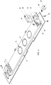
- Fig. 1 shows the upper lid of a metallic cabinet inside of which appliances of a telecommunication system on which energy and signal carrying cables arriving from outside abut.
- lid 1 is provided with two cable clamping devices according to the invention identified by A and B.
- the figure comprises labels showing some recurring typologies of cables usually connected inside of such cabinets.
- each cable passing device is set up by at least two metallic terminal plates 2 and 3, which may also be interconnected in a substantially permanent way through suitable co-operating means of alignment and mechanic connection 4 and 5, in order to set up a box-shaped body.
- One of the two terminal plates, in the example plate 2 will be fixed by means of screws in order to cover internally the surface of an opening in the metallic wall of the cabinet (of lid).
- Both terminal plates 2 and 3 of device are provided with an identical drilling whereby the corresponding holes of the plurality of holes present in both plates 2 and 3 after their coupling turn out to be perfectly aligned or presenting coinciding axis between them.
- the holes may be all of the same diameter (foreseeing passage of cables with the same diameter), but in the major part of applications there may be holes with the same diameter and different from the diameter of another group of holes.
- the holes 9 have a larger diameter than the holes 7 which at their time have a greater diameter than the other holes 6.
- terminal plates 2 and 3 there may be also holes of great diameter, in the range of several centimetres, in that case the conductors of a shielded cable containing a large number of isolated conductors have to be abutted inside the cabinet, for example several tens of telephone duplex cables.
- the plates of the device according to the invention may be predisposed with one or more of these holes with a large diameter, on the other hand functionally maintained obstructed maintaining the metallic shearing disc in seat, by means of small metallic bridges 11 according to common definition techniques for the shearing of such particulars.
- the discs 10 may be only individually removed if it is necessary to use the hole for the passage of such cable with greater diameteres.
- At least a third metallic plate 12, illustrated in Fig. 3 has such dimensions that it may be inserted by sliding between the 2 plates 2 and 3 constituting the box-shaped body of Fig. 2.
- this third intermediate plate 12 is provided with a perforation, perfectly coinciding with the perforations of the others two terminal plates 2 and 3.
- the intermediate plate 12 is provided at one end of a block 13 which can be solidly connected to the late by means of studs 14 or other mechanical connecting means.
- Terminal block 13 is provided with a hole 15, which may be engaged by a draught organ, as it will be, illustrated hereafter in the present description.
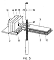
- FIG. 4 A complete view of the cable-passing device according to the invention is shown in Fig. 4.
- An analogous block 16 is can be fixed by studs 17 or other mechanic coupling means to terminal plate 2, in a juxtaposed position to that of block 13 fixed to the sliding intermediate plate 12. Also block 16 is provided with a hole, which in this case is threaded, through which the driving screw 19 is screwed in, a tang 20 of which goes through the hole of block 13 and blocked on the other side of block 13 by an elastic washer 21 or by a split pin or another similar blocking mean.
- the device is such that, rotating the screw 19 in the threaded seat 18 of block 16 which is fixed to terminal plate 2, the sliding intermediate plate 12 can be moved in one or the other direction, aligning or throwing out of alignment the holes of the intermediate plate 12 with respect to the corresponding holes of the 2 terminal plates 2 and 3.
- each cable C to abut inside the cabinet is entered through the trio of holes of the three plates 2, 3 and 12, in the conditions of perfect alignment of the respective perforations with the part of metallic shielding braiding exhibited cutting and withdrawing a possible external isolation cladding correctly set, completing the insertion of all cables foreseen to be abutted inside the cabinet through as many holes, that is trios of aligned holes with a diameter suitable for the type of cable.
- the material or materials for the construction of carpenter stopper device according to the invention can be those commonly used for the realisation of such metallic structures of electromagnetic containment.
- Stainless steels, titan, copper and other metallic alloys can be satisfactorily employed.
- the thicknesses of the two terminal plates 2 and 3 and of the sliding intermediate plate 12 can be commensurate in function of type of cables taking into account the necessity to adjust the relative thicknesses of the three or more perforated plates that compose the device according to the invention as well as the finishing of the edges of the holes in order to assure, on one side, a good ohm contact with metallic shielding braids of the clamped cable and, on the other side, avoiding that the clamping function can engrave and damaging the cable.
Landscapes
- Engineering & Computer Science (AREA)
- Microelectronics & Electronic Packaging (AREA)
- Shielding Devices Or Components To Electric Or Magnetic Fields (AREA)
- Installation Of Indoor Wiring (AREA)
- Insertion, Bundling And Securing Of Wires For Electric Apparatuses (AREA)
Applications Claiming Priority (2)
| Application Number | Priority Date | Filing Date | Title |
|---|---|---|---|
| IT98MI001279A ITMI981279A1 (it) | 1998-06-05 | 1998-06-05 | Dispositivo serracavi e di drenaggio verso massa delle correnti parassite indotte su cavi schermati all'attraversamento di una |
| ITMI981279 | 1998-06-05 |
Publications (3)
| Publication Number | Publication Date |
|---|---|
| EP0963147A2 true EP0963147A2 (de) | 1999-12-08 |
| EP0963147A3 EP0963147A3 (de) | 2000-07-19 |
| EP0963147B1 EP0963147B1 (de) | 2002-12-04 |
Family
ID=11380189
Family Applications (1)
| Application Number | Title | Priority Date | Filing Date |
|---|---|---|---|
| EP19990110692 Expired - Lifetime EP0963147B1 (de) | 1998-06-05 | 1999-06-02 | Klammeranordnung für Signalübertragungskabel zur Erdung der geflechten Abschirmung |
Country Status (4)
| Country | Link |
|---|---|
| EP (1) | EP0963147B1 (de) |
| AR (1) | AR019613A1 (de) |
| DE (1) | DE69904261T2 (de) |
| IT (1) | ITMI981279A1 (de) |
Cited By (4)
| Publication number | Priority date | Publication date | Assignee | Title |
|---|---|---|---|---|
| US6784368B2 (en) * | 2000-04-19 | 2004-08-31 | Toyota Jidosha Kabushiki Kaisha | Shield connection structure of cable |
| EP1740034A1 (de) * | 2000-04-03 | 2007-01-03 | Matsushita Electric Industrial Co., Ltd. | Tragbares Funkgerät |
| CN111908252A (zh) * | 2020-09-23 | 2020-11-10 | 赖国营 | 电缆收盘机 |
| CN115734596A (zh) * | 2022-10-28 | 2023-03-03 | 贵州电网有限责任公司 | 一种探测器用铜网展开装置 |
Families Citing this family (2)
| Publication number | Priority date | Publication date | Assignee | Title |
|---|---|---|---|---|
| DE10312920B4 (de) * | 2003-03-22 | 2005-08-04 | Sma Technologie Ag | Vorrichtung zur Fixierung eines Rundsteckers in der Steckerbuchse |
| CN108831604B (zh) * | 2018-07-16 | 2023-09-29 | 中国人民解放军海军航空大学青岛校区 | 一种飞机用电磁屏蔽线缆 |
Family Cites Families (2)
| Publication number | Priority date | Publication date | Assignee | Title |
|---|---|---|---|---|
| IT1256057B (it) * | 1992-11-20 | 1995-11-23 | Italtel Spa | Dispositivo per la schermatura di cavi elettrici che si attestano su armadi contenenti apparecchiature di telecomunicazioni |
| US5742003A (en) * | 1996-08-12 | 1998-04-21 | Ho; Hsin Chien | Computer terminal box with improved grounding structure |
-
1998
- 1998-06-05 IT IT98MI001279A patent/ITMI981279A1/it unknown
-
1999
- 1999-06-02 DE DE1999604261 patent/DE69904261T2/de not_active Expired - Fee Related
- 1999-06-02 EP EP19990110692 patent/EP0963147B1/de not_active Expired - Lifetime
- 1999-06-03 AR ARP990102622 patent/AR019613A1/es unknown
Cited By (4)
| Publication number | Priority date | Publication date | Assignee | Title |
|---|---|---|---|---|
| EP1740034A1 (de) * | 2000-04-03 | 2007-01-03 | Matsushita Electric Industrial Co., Ltd. | Tragbares Funkgerät |
| US6784368B2 (en) * | 2000-04-19 | 2004-08-31 | Toyota Jidosha Kabushiki Kaisha | Shield connection structure of cable |
| CN111908252A (zh) * | 2020-09-23 | 2020-11-10 | 赖国营 | 电缆收盘机 |
| CN115734596A (zh) * | 2022-10-28 | 2023-03-03 | 贵州电网有限责任公司 | 一种探测器用铜网展开装置 |
Also Published As
| Publication number | Publication date |
|---|---|
| EP0963147A3 (de) | 2000-07-19 |
| EP0963147B1 (de) | 2002-12-04 |
| ITMI981279A1 (it) | 1999-12-05 |
| DE69904261D1 (de) | 2003-01-16 |
| DE69904261T2 (de) | 2003-08-21 |
| AR019613A1 (es) | 2002-02-27 |
Similar Documents
| Publication | Publication Date | Title |
|---|---|---|
| US4364625A (en) | Electrical jack assembly | |
| RU2137271C1 (ru) | Присоединительный элемент | |
| US5274527A (en) | Housing with plug-in connections | |
| EP0963147B1 (de) | Klammeranordnung für Signalübertragungskabel zur Erdung der geflechten Abschirmung | |
| EP1618578B1 (de) | Schaltschütz mit anschlussmodul zum ansteuern des magnetantriebes | |
| DE69405377T2 (de) | Kabelverschlussvorrichtung | |
| US5933319A (en) | Electrical panelboard having an enclosure over an exposed terminal of circuit breaker mounted to a panel of the electrical panelboard | |
| US7140926B2 (en) | Telecommunications terminal module | |
| JPH07264749A (ja) | 複数のシールド線用の接続箱 | |
| IL37571A (en) | Improvements relating to electrical switch devices | |
| DE102022203408A1 (de) | Gehäusemodul, Isolierstoffgehäuse und Schutzschaltgerät | |
| DE4311883A1 (de) | EIB-Modul | |
| EP0218281A1 (de) | Diebstahlsicherungssystem für elektrische Apparate, und für dieses System bestimmte Steckdose | |
| IL108297A (en) | Connection and tap sleeve for coaxial cables or the like | |
| DE4438215A1 (de) | NH-Sicherungs-Lasttrennschalter mit Sicherungsüberwachung | |
| IE53548B1 (en) | A distributor strip for a telephone exchange | |
| DE3119256A1 (de) | "elektrisches schaltgeraet mit sichtanzeige der jeweiligen schaltstellung" | |
| JPH0594755A (ja) | 端子コネクタブロツク付き電子式回路遮断器 | |
| AU691182B2 (en) | Loading coil device | |
| JP3664323B2 (ja) | 高周波信号処理装置 | |
| DE4345217C2 (de) | Anschlußkabel zur Bildung einer Anschlußeinrichtung für ein Datennetz | |
| EP0162147B1 (de) | Filter-Baugruppe für Nachrichten- und Steuerleitungen, die zur Einführung in geschirmte Kabinen und Räume bestimmt sind | |
| DE3113127C2 (de) | Netztrenngerät | |
| DE8019255U1 (de) | Elektrischer Installationsschalter und Leitungsschutzschalter | |
| MX9700014A (es) | Procedimiento para la conmutacion ininterrumpida de cable de telecomunicacion y dispositivo de comunicacion apropiados. |
Legal Events
| Date | Code | Title | Description |
|---|---|---|---|
| PUAI | Public reference made under article 153(3) epc to a published international application that has entered the european phase |
Free format text: ORIGINAL CODE: 0009012 |
|
| AK | Designated contracting states |
Kind code of ref document: A2 Designated state(s): DE FR SE |
|
| AX | Request for extension of the european patent |
Free format text: AL;LT;LV;MK;RO;SI |
|
| PUAL | Search report despatched |
Free format text: ORIGINAL CODE: 0009013 |
|
| AK | Designated contracting states |
Kind code of ref document: A3 Designated state(s): AT BE CH CY DE DK ES FI FR GB GR IE IT LI LU MC NL PT SE |
|
| AX | Request for extension of the european patent |
Free format text: AL;LT;LV;MK;RO;SI |
|
| RIC1 | Information provided on ipc code assigned before grant |
Free format text: 7H 05K 9/00 A, 7H 01R 9/05 B |
|
| 17P | Request for examination filed |
Effective date: 20010110 |
|
| AKX | Designation fees paid |
Free format text: DE FR SE |
|
| 17Q | First examination report despatched |
Effective date: 20010522 |
|
| GRAG | Despatch of communication of intention to grant |
Free format text: ORIGINAL CODE: EPIDOS AGRA |
|
| GRAG | Despatch of communication of intention to grant |
Free format text: ORIGINAL CODE: EPIDOS AGRA |
|
| GRAH | Despatch of communication of intention to grant a patent |
Free format text: ORIGINAL CODE: EPIDOS IGRA |
|
| GRAH | Despatch of communication of intention to grant a patent |
Free format text: ORIGINAL CODE: EPIDOS IGRA |
|
| GRAA | (expected) grant |
Free format text: ORIGINAL CODE: 0009210 |
|
| RAP1 | Party data changed (applicant data changed or rights of an application transferred) |
Owner name: CNX S.P.A. Owner name: ITALTEL S.P.A. |
|
| AK | Designated contracting states |
Kind code of ref document: B1 Designated state(s): DE FR SE |
|
| REF | Corresponds to: |
Ref document number: 69904261 Country of ref document: DE Date of ref document: 20030116 |
|
| REG | Reference to a national code |
Ref country code: SE Ref legal event code: TRGR |
|
| ET | Fr: translation filed | ||
| PLBE | No opposition filed within time limit |
Free format text: ORIGINAL CODE: 0009261 |
|
| STAA | Information on the status of an ep patent application or granted ep patent |
Free format text: STATUS: NO OPPOSITION FILED WITHIN TIME LIMIT |
|
| 26N | No opposition filed |
Effective date: 20030905 |
|
| PGFP | Annual fee paid to national office [announced via postgrant information from national office to epo] |
Ref country code: SE Payment date: 20040604 Year of fee payment: 6 |
|
| PGFP | Annual fee paid to national office [announced via postgrant information from national office to epo] |
Ref country code: FR Payment date: 20040608 Year of fee payment: 6 |
|
| PGFP | Annual fee paid to national office [announced via postgrant information from national office to epo] |
Ref country code: DE Payment date: 20040610 Year of fee payment: 6 |
|
| PG25 | Lapsed in a contracting state [announced via postgrant information from national office to epo] |
Ref country code: SE Free format text: LAPSE BECAUSE OF NON-PAYMENT OF DUE FEES Effective date: 20050603 |
|
| PG25 | Lapsed in a contracting state [announced via postgrant information from national office to epo] |
Ref country code: DE Free format text: LAPSE BECAUSE OF NON-PAYMENT OF DUE FEES Effective date: 20060103 |
|
| EUG | Se: european patent has lapsed | ||
| PG25 | Lapsed in a contracting state [announced via postgrant information from national office to epo] |
Ref country code: FR Free format text: LAPSE BECAUSE OF NON-PAYMENT OF DUE FEES Effective date: 20060228 |
|
| REG | Reference to a national code |
Ref country code: FR Ref legal event code: ST Effective date: 20060228 |