EP0962676B1 - Dispositif de palier avec des surfaces de palier sphériques - Google Patents
Dispositif de palier avec des surfaces de palier sphériques Download PDFInfo
- Publication number
- EP0962676B1 EP0962676B1 EP99110521A EP99110521A EP0962676B1 EP 0962676 B1 EP0962676 B1 EP 0962676B1 EP 99110521 A EP99110521 A EP 99110521A EP 99110521 A EP99110521 A EP 99110521A EP 0962676 B1 EP0962676 B1 EP 0962676B1
- Authority
- EP
- European Patent Office
- Prior art keywords
- bearing
- assembly
- cylindrical bore
- cylindrical
- bore
- Prior art date
- Legal status (The legal status is an assumption and is not a legal conclusion. Google has not performed a legal analysis and makes no representation as to the accuracy of the status listed.)
- Expired - Lifetime
Links
Images
Classifications
-
- F—MECHANICAL ENGINEERING; LIGHTING; HEATING; WEAPONS; BLASTING
- F16—ENGINEERING ELEMENTS AND UNITS; GENERAL MEASURES FOR PRODUCING AND MAINTAINING EFFECTIVE FUNCTIONING OF MACHINES OR INSTALLATIONS; THERMAL INSULATION IN GENERAL
- F16C—SHAFTS; FLEXIBLE SHAFTS; ELEMENTS OR CRANKSHAFT MECHANISMS; ROTARY BODIES OTHER THAN GEARING ELEMENTS; BEARINGS
- F16C23/00—Bearings for exclusively rotary movement adjustable for aligning or positioning
- F16C23/02—Sliding-contact bearings
- F16C23/04—Sliding-contact bearings self-adjusting
- F16C23/043—Sliding-contact bearings self-adjusting with spherical surfaces, e.g. spherical plain bearings
- F16C23/045—Sliding-contact bearings self-adjusting with spherical surfaces, e.g. spherical plain bearings for radial load mainly, e.g. radial spherical plain bearings
-
- F—MECHANICAL ENGINEERING; LIGHTING; HEATING; WEAPONS; BLASTING
- F16—ENGINEERING ELEMENTS AND UNITS; GENERAL MEASURES FOR PRODUCING AND MAINTAINING EFFECTIVE FUNCTIONING OF MACHINES OR INSTALLATIONS; THERMAL INSULATION IN GENERAL
- F16C—SHAFTS; FLEXIBLE SHAFTS; ELEMENTS OR CRANKSHAFT MECHANISMS; ROTARY BODIES OTHER THAN GEARING ELEMENTS; BEARINGS
- F16C17/00—Sliding-contact bearings for exclusively rotary movement
- F16C17/10—Sliding-contact bearings for exclusively rotary movement for both radial and axial load
-
- F—MECHANICAL ENGINEERING; LIGHTING; HEATING; WEAPONS; BLASTING
- F16—ENGINEERING ELEMENTS AND UNITS; GENERAL MEASURES FOR PRODUCING AND MAINTAINING EFFECTIVE FUNCTIONING OF MACHINES OR INSTALLATIONS; THERMAL INSULATION IN GENERAL
- F16C—SHAFTS; FLEXIBLE SHAFTS; ELEMENTS OR CRANKSHAFT MECHANISMS; ROTARY BODIES OTHER THAN GEARING ELEMENTS; BEARINGS
- F16C33/00—Parts of bearings; Special methods for making bearings or parts thereof
- F16C33/02—Parts of sliding-contact bearings
- F16C33/04—Brasses; Bushes; Linings
- F16C33/06—Sliding surface mainly made of metal
- F16C33/10—Construction relative to lubrication
-
- F—MECHANICAL ENGINEERING; LIGHTING; HEATING; WEAPONS; BLASTING
- F16—ENGINEERING ELEMENTS AND UNITS; GENERAL MEASURES FOR PRODUCING AND MAINTAINING EFFECTIVE FUNCTIONING OF MACHINES OR INSTALLATIONS; THERMAL INSULATION IN GENERAL
- F16C—SHAFTS; FLEXIBLE SHAFTS; ELEMENTS OR CRANKSHAFT MECHANISMS; ROTARY BODIES OTHER THAN GEARING ELEMENTS; BEARINGS
- F16C35/00—Rigid support of bearing units; Housings, e.g. caps, covers
- F16C35/02—Rigid support of bearing units; Housings, e.g. caps, covers in the case of sliding-contact bearings
Definitions
- the invention relates generally, but not exclusively, to composite journal bearings, and to an improved composite ball and socket journal bearing assembly as defined by the features of the preamble of claim 1 and known from DE-A-2 915 088.
- references herein to a surface of spherical shape are to be understood as relating to surfaces which have the shape of a part of a sphere.
- a bearing assembly comprising an outer non-rotating sub-assembly including an outer housing having a cylindrical bore, and an outer bearing including an outer cylindrical surface engaging the cylindrical bore of the outer housing, and a bore defined by a spherical inwardly facing bearing surface, and an inner movable sub-assembly including an inner bearing having an outer surface defined by a spherical outwardly facing bearing surface engaging the inwardly facing bearing surface of the outer bearing, and an internal cylindrical bore.
- the outer bearing can have an inner part fabricated of a friction reducing material, which is preferably cast between the inner and outer bearing after assembly thereof.
- a bearing assembly according to the invention is characterized in that the internal cylindrical bore is adapted to receive a movable member and the outer bearing includes an outer part fabricated of filament wound fibreglass and epoxy resin matrix, and an inner bearing part fabricated of woven PTFE fabric.
- the inner movable sub-assembly may be a rotatable sub-assembly comprising a sleeve including a cylindrical outer surface received in the internal bore of the inner bearing, and an internal bore adapted to receive a rotating member to be fixed thereto for common rotation therewith.
- the outer sub-assembly comprises an outer bearing, having an inner part, which is fabricated of a self-lubricating composite, including PFTE and another material, e.g. fibreglass reinforced plastic or bearing metal.
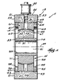
- bearing assembly 11 Shown in the drawings is a bearing assembly 11 comprising an outer non-rotating sub-assembly 13 and an inner rotating sub-assembly 15.
- the outer non-rotating sub-assembly 13 includes an outer housing which, (while other constructions can be employed) in the disclosed construction, is in the form of a pillow block housing 21 including an external surface having spaced side surface portions 23, a generally semi-cylindrical outer surface portion 25 extending between the side surface portions 23, and a cylindrical bore 27 having an axis 29 and extending between the side surface portions 23.
- the pillow block housing 21 also includes a lubrication conduit 31 communicating with the cylindrical bore 27, extending to the semi-cylindrical outer surface portion 25 of the external surface, and communicating with a suitable lubrication source 35.
- the pillow block housing 21 can be formed in any suitable way from any suitable material.
- the outer non-rotating sub-assembly 13 also includes an outer bearing 41 which is located in the cylindrical bore 27 in the pillow block housing 21 and which includes an outer cylindrical surface 43 engaging the cylindrical bore 27 of the pillow block housing 21, and a bore defined by an inwardly facing, spherically shaped, bearing surface 45.
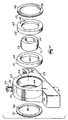
- the outer bearing 41 comprises first and second bearing segments 51 and 53 which are axially spaced from each other to define therebetween a space 55 which communicates with the lubrication conduit 31.
- the first bearing segment 51 includes an outer part or portion 61 providing a first portion of the cylindrical outer surface 43 of the outer bearing 41, and an inner part or portion 63 providing a first portion of the spherical inwardly facing,spherically shaped, bearing surface 45 of the outer bearing 41.
- the second bearing segment 53 includes an outer part or portion 65 providing a second portion of the cylindrical outer surface of the outer bearing, and an inner part or portion 67 providing a second portion of the inwardly facing, spherically shaped, bearing surface 45 of the outer bearing 41.
- the first and second bearing segments 51 and 53 are preferably of equal axial dimension between the opposing radial surfaces thereof.
- the inner portions 63 and 67, including the inwardly facing, spherically shaped, bearing surfaces 45, of the first and second bearing segments 51 and 53, are fabricated from a woven PTFE fabric, and the outer portions 61 and 65 of the first and second bearing segments 51 and 53 are fabricated from a filament wound fiberglass and epoxy resin matrix and are respectively bonded to the inner parts or portions 63 and 67 providing the inwardly facing spherically shaped bearing surface 45.
- the outer bearing segments 51 and 53 are filament wound on a tooling ball which is much narrower than the inner race used in the mounted block. This method of manufacturing allows for more units to be wound at one time, allows for less material to be used in the process (less scrap), and eliminates the damaging of the inner race during the cut off process.
- the inner rotating sub-assembly 15 includes an inner bearing 71 including an outer surface defined by an outwardly facing, spherically shaped bearing surface 73 engaging the inwardly facing, spherically shaped, bearing surface portions of the first and second outer bearing segments 51 and 53.
- the inner bearing 71 also includes an internal cylindrical bore 75.
- the inner rotating sub-assembly 15 includes an inner sleeve 81 having a cylindrical outer surface 83 received in the internal cylindrical bore 75 of the inner bearing 71, and an internal bore 85 adapted to receive a rotating member 91 fixed to the sleeve 81 for common rotation therewith.
- the inner bearing 71 can be fabricated from any suitable material and, in the disclosed construction, is preferably fabricated from steel. Any suitable construction can be employed for the inner sleeve 81 and the rotating member 91. In some constructions, the inner sleeve 81 can be omitted and, in other instances, the inner sleeve 81 can constitute the rotating member 91.
- the engagement between the outwardly facing, convexly formed, spherical bearing surface 73 of the inner bearing 71 and the inwardly facing, concavely formed, spherical bearing surface 45 formed by the first and second outer bearing-segments 51 and 53 serves to retain the bearing segments 51 and 53 in axially spaced relation to each other and to locate the space 55 for communication with the lubrication conduit 31.
- the space 55 is defined, in part, by the outwardly facing, convexly formed, spherical bearing surface 73 and, therefore, the spherical bearing surfaces 45 and 73 receive lubricant from the space 55.
- Means are provided for retaining the first and second bearing segments 51 and 53 in spaced relation to each other and against axially outward movement relative to the inner bearing 41 and relative to the pillow block housing 21. While other constructions can be employed, in the disclosed construction, such means comprises the provision, in the pillow block housing 21, adjacent the opposite ends of the cylindrical bore 27 therein, of respective threaded portions 93, and the provision, at each end of the cylindrical bore 27, of respective covers or retainers 95 which are threadedly received by the threaded portions 93. While other constructions can be employed, in the disclosed construction, the covers or retainers 95 comprise annular washers having cylindrical outer edges or edge portions 97 threadedly received in the threaded portions 93 of the pillow block housing 21.
- covers, or retainers or washers include respective central bores 99 with diameters greater than that of the spherical bearing surface 45 adjacent the outer ends thereof so as to engage the side surfaces of the bearing segments 51 and 53 to prevent axial outward movement thereof.
- the covers or retainers 95 also serve to enable adjustment for clearance and end play.
- the disclosed bearing assembly construction improves reliability, life, and consistency of bearing operation under high loads and small angles of oscillation.
- the disclosed bearing assemblies also provide lower friction under boundary lubrication conditions.
- the disclosed bearing assembly construction also allows for the use of standard bearing blocks and seals for applications in dusty and dirty environments.
- the disclosed bearing assemblies can be run "dry", i.e., without lubrication, if the mating bearing surface engaging the bearing segments 51 and 53 has the proper corrosion protection for the operating conditions. If desired, the life of the disclosed bearing assemblies can be extended by adding lubrication to the gap or space 55 which is located between the bearing segments 51 and 53 and which acts as a reservoir.
- the disclosed bearing assembly construction also provides a major advantage in that the disclosed bearing assembly construction, as compared to a rolling element bearing, has the ability to withstand high loads with very small angles of oscillation without fretting, brinelling, spalling, galling, and fatigue of the mating surface.
Claims (8)
- Ensemble formant palier (11) comprenant :- un sous-ensemble non rotatif extérieur (13) comprenant- un logement extérieur (21) comportant un alésage cylindrique (27), et- un palier extérieur (41) comprenant une surface cylindrique extérieure (43) en contact avec ledit alésage cylindrique (27) dudit logement extérieur (21), et un alésage défini par une surface d'appui sphérique (45) tournée vers l'intérieur, et- un sous-ensemble mobile intérieur (15) comprenant- un palier intérieur (71) comportant une surface extérieure définie par une surface d'appui sphérique (73) tournée vers l'extérieur et en contact avec ladite surface d'appui sphérique (45) tournée vers l'intérieur dudit palier extérieur (41), et- un alésage cylindrique interne (75), caractérisé en ce que- ledit alésage cylindrique interne (75) est adapté pour recevoir un élément mobile (81, 91) et- ledit palier extérieur (41) comprend- une partie de palier extérieure (61, 65) constituée d'un enroulement filamentaire de fibres de verre et d'une matrice en résine époxy, et- une partie de palier intérieure (63, 67) constituée d'un tissé de polyéthylènetéréphtalate (PTFE).
- Ensemble formant palier selon la revendication 1, caractérisé en ce que ledit sous-ensemble mobile intérieur (15) a la forme d'un sous-ensemble rotatif intérieur comportant un manchon (81) comprenant une surface extérieure cylindrique (83) reçue dans ledit alésage cylindrique interne (75) dudit palier intérieur (71), et un alésage interne (85) dudit manchon (81) est adapté pour recevoir un élément rotatif (91) devant être fixé à celui-ci pour être entraîné en rotation avec lui.
- Ensemble formant palier selon la revendication 1 ou la revendication 2, caractérisé en ce que- ledit palier extérieur (41) comprend- un premier segment de palier (51) comprenant une première partie extérieure (61) et une première partie intérieure (63), et- un second segment de palier (53) situé dans une relation espacée par rapport audit premier segment de palier (51), et comprenant une seconde partie extérieure (65) et une seconde partie intérieure (67),- pour qu'ainsi lesdites première et seconde parties extérieures (61, 65) constituent respectivement des première et seconde parties de ladite surface cylindrique extérieure (43), et- lesdites première et seconde parties intérieures (63 et 67) constituent respectivement des première et seconde parties de ladite surface d'appui sphérique (45) tournée vers l'intérieur dudit palier extérieur (41).
- Ensemble formant palier selon la revendication 3, caractérisé en ce que- lesdits premier et second segments de palier (51, 53) sont définis ici entre un espace (55) s'étendant jusqu'à ladite surface d'appui sphérique (73) tournée vers l'extérieur dudit palier intérieur (71), et- ledit boîtier extérieur (21) comprend une surface extérieure et un conduit de lubrification (31) communiquant entre ledit espace et ladite surface externe.
- Ensemble formant palier selon l'une quelconque des revendications précédentes, caractérisé en ce qu'il comprend des moyens (95) pour empêcher un déplacement axial dudit palier extérieur (41) par rapport audit logement extérieur (21).
- Ensemble formant palier selon l'une quelconque des revendications précédentes, caractérisé en ce que- ledit alésage cylindrique (27) dudit logement extérieur (21) comprend un axe (29) et des première et seconde extrémités (23) espacées axialement, et- ledit ensemble formant palier comprend en outre des premier et second capots (95) respectivement fixés audit logement extérieur, à proximité desdites première et seconde extrémités dudit alésage cylindrique (27), et dans des positions aptes à fermer ce dernier et à empêcher un déplacement axial dudit palier extérieur (41) par rapport audit logement extérieur.
- Ensemble formant palier selon la revendication 6, caractérisé en ce que- lesdites première et seconde extrémités (23) dudit alésage cylindrique (27) sont des extrémités filetées (93), et- lesdits premier et second capots (95) sont des éléments annulaires respectivement accouplés par vissage avec lesdites première et seconde extrémités filetées (93).
- Ensemble formant palier (11) selon la revendication 1, dans lequel- ledit logement extérieur comprend un logement formant support (21) comprenant une surface externe (23, 25) et ledit alésage cylindrique (27), des première et seconde extrémités filetées (93), et un conduit de lubrification (31) communiquant entre ladite surface externe et ledit alésage cylindrique,- ledit palier extérieur (41) comprenant- un premier segment de palier (51) comprenant une première partie extérieure (61) et une première partie intérieure (63), et- un second segment de palier (53) situé dans une relation espacée axialement par rapport audit premier segment de palier pour définir entre eux un espace (55) communiquant avec ledit conduit de lubrification (31), et comprenant une seconde partie extérieure (65) et une seconde partie intérieure (67),- pour qu'ainsi lesdites première et seconde parties extérieures (61, 65) constituent respectivement des première et seconde parties de ladite surface cylindrique extérieure (43) en contact avec ledit alésage cylindrique (27), et- lesdites première et seconde parties intérieures (63 et 67) constituent respectivement des première et seconde parties de ladite surface d'appui sphérique (45) dirigée vers l'intérieur,- ledit sous-ensemble non rotatif extérieur (13) comprend en outre des premier et second capots annulaires (95) respectivement accouplés par vissage avec lesdites première et secondes extrémités filetées (93) dudit alésage cylindrique, et dans des positions aptes à fermer ledit alésage cylindrique et à empêcher un déplacement axial dudit palier extérieur (41) par rapport audit logement formant support (21), et- ledit sous-ensemble rotatif intérieur (15) comprend un manchon (81) comprenant- une surface extérieure cylindrique (83) reçue dans ledit alésage interne (75) dudit palier intérieur (71), et- un alésage interne (85) adapté pour recevoir un élément rotatif (91) devant être fixé à lui pour être entraîné en rotation avec lui.
Applications Claiming Priority (2)
| Application Number | Priority Date | Filing Date | Title |
|---|---|---|---|
| US09/090,115 US6004037A (en) | 1998-06-04 | 1998-06-04 | Bearing assembly with spherical bearing surfaces |
| US90115 | 1998-06-04 |
Publications (3)
| Publication Number | Publication Date |
|---|---|
| EP0962676A2 EP0962676A2 (fr) | 1999-12-08 |
| EP0962676A3 EP0962676A3 (fr) | 2000-11-29 |
| EP0962676B1 true EP0962676B1 (fr) | 2006-01-25 |
Family
ID=22221393
Family Applications (1)
| Application Number | Title | Priority Date | Filing Date |
|---|---|---|---|
| EP99110521A Expired - Lifetime EP0962676B1 (fr) | 1998-06-04 | 1999-06-01 | Dispositif de palier avec des surfaces de palier sphériques |
Country Status (5)
| Country | Link |
|---|---|
| US (1) | US6004037A (fr) |
| EP (1) | EP0962676B1 (fr) |
| JP (1) | JP2000009137A (fr) |
| AT (1) | ATE316620T1 (fr) |
| DE (1) | DE69929554T2 (fr) |
Cited By (1)
| Publication number | Priority date | Publication date | Assignee | Title |
|---|---|---|---|---|
| EP3988807A1 (fr) * | 2020-10-26 | 2022-04-27 | General Electric Company | Palier lisse sphérique pour un groupe motopropulseur d'éolienne |
Families Citing this family (34)
| Publication number | Priority date | Publication date | Assignee | Title |
|---|---|---|---|---|
| US5989709A (en) * | 1998-04-30 | 1999-11-23 | Gore Enterprises Holdings, Inc. | Polytetrafluoroethylene fiber |
| US6623238B2 (en) | 1998-08-21 | 2003-09-23 | Honeywell International, Inc. | Air turbine starter with seal assembly |
| JP2001193735A (ja) * | 2000-01-05 | 2001-07-17 | Minebea Co Ltd | 球面滑り軸受のトルク調節機構 |
| JP2001193734A (ja) | 2000-01-05 | 2001-07-17 | Minebea Co Ltd | 球面滑り軸受の固定方法 |
| FR2833572B1 (fr) * | 2001-12-18 | 2004-04-02 | Airbus France | Procede et dispositif de montage d'un train d'atterrissage sur une structure d'aeronef et aeronef comportant un tel train |
| US6681579B2 (en) | 2002-02-07 | 2004-01-27 | Honeywell International, Inc. | Air turbine starter with fluid flow control |
| US6860638B2 (en) * | 2002-03-04 | 2005-03-01 | Polygon Company, Inc. | Spherical bearing |
| US9004491B2 (en) | 2002-06-21 | 2015-04-14 | Inpro/Seal Llc | Shaft seal assembly |
| US7396017B2 (en) * | 2002-06-21 | 2008-07-08 | Isotech Of Illinois, Inc. | Shaft seal assembly |
| US8979093B2 (en) * | 2002-06-21 | 2015-03-17 | Inpro/Seal, LLC | Pressure balanced shaft seal assembly |
| US7726661B2 (en) | 2002-06-21 | 2010-06-01 | Inpro/Seal Llc | Pressure balanced shaft seal assembly |
| US7090403B2 (en) * | 2002-06-21 | 2006-08-15 | Isotech Of Illinois, Inc. | Articulated seal |
| US7010721B2 (en) * | 2003-09-29 | 2006-03-07 | International Business Machines Corporation | File system journal management |
| US7172352B2 (en) * | 2003-12-09 | 2007-02-06 | Hewlett-Packard Development Company, L.P. | Bearing |
| US7033133B2 (en) | 2003-12-10 | 2006-04-25 | Honeywell International, Inc. | Air turbine starter having a low differential check valve |
| US7033134B2 (en) | 2004-02-24 | 2006-04-25 | Honeywell International, Inc. | Air turbine starter having a force balanced, pressure energized, weighted check valve |
| US7014419B2 (en) * | 2004-02-27 | 2006-03-21 | Honeywell International, Inc. | Passive improved air turbine starter lubrication system |
| DE102004062842B3 (de) * | 2004-12-27 | 2006-04-27 | Ab Skf | Lageranordnung |
| US7461902B1 (en) | 2005-10-26 | 2008-12-09 | Robert Darst | Auger car bearing support |
| KR100752619B1 (ko) | 2005-11-03 | 2007-08-29 | 주식회사 동아오토모티브 | 너클 일체형 필로볼조인트 |
| BE1017140A3 (nl) * | 2006-05-15 | 2008-03-04 | Hansen Transmissions Int | Drukkam voor een tandwieloverbrenging. |
| US20080031559A1 (en) * | 2006-07-13 | 2008-02-07 | Roller Bearing Company Of America, Inc. | Hybrid spherical bearing |
| US7828482B2 (en) * | 2006-08-28 | 2010-11-09 | Roller Bearing Company Of America, Inc. | Tungsten carbide enhanced bearing |
| US20080304902A1 (en) * | 2006-11-01 | 2008-12-11 | Tomasz Buchner | Ball joint |
| US20100264600A1 (en) * | 2009-04-21 | 2010-10-21 | Richard Lee Willms | Pneumatic mechanical seal |
| US8393796B2 (en) * | 2010-07-29 | 2013-03-12 | Ontario Drive & Gear Limited | Heavy duty bearing support system for ATV |
| US8500333B2 (en) * | 2011-05-24 | 2013-08-06 | Siemens Industry, Inc. | Self aligning oil film bearing |
| ITBO20110534A1 (it) | 2011-09-16 | 2013-03-17 | Wam Ind Spa | Elemento di supporto intermedio per una coclea |
| US8753014B2 (en) | 2012-01-03 | 2014-06-17 | New Way Machine Components, Inc. | Air bearing for use as a seal |
| US10598222B2 (en) | 2012-01-03 | 2020-03-24 | New Way Machine Components, Inc. | Air bearing for use as seal |
| CN105705843A (zh) * | 2013-09-30 | 2016-06-22 | 益保密封有限公司 | 轴封总成 |
| TWI735960B (zh) * | 2018-09-28 | 2021-08-11 | 美商英普羅密封有限責任公司 | 環狀密封組件 |
| CN109340268A (zh) * | 2018-10-31 | 2019-02-15 | 中船动力研究院有限公司 | 一种轴承支撑装置 |
| DE102020111280A1 (de) | 2020-04-24 | 2021-10-28 | THK RHYTHM AUTOMOTIVE GmbH | Kugelzapfen sowie Verfahren zur Herstellung eines Kugelzapfens |
Family Cites Families (14)
| Publication number | Priority date | Publication date | Assignee | Title |
|---|---|---|---|---|
| FR1053655A (fr) * | 1952-04-10 | 1954-02-04 | Perfectionnements aux paliers sphériques | |
| FR68461E (fr) * | 1954-06-04 | 1958-04-30 | Soulard Charles Georges | Palier perfectionné |
| US2906568A (en) * | 1956-03-13 | 1959-09-29 | Lockheed Aircraft Corp | Spherical bearing |
| DE1952621U (de) * | 1966-10-27 | 1966-12-29 | Artur Seyfert K G Kugellagerfa | Gelenkstangenkopf. |
| US3974009A (en) * | 1969-05-21 | 1976-08-10 | Rex Chainbelt Inc. | Method for making ball and socket type bearings in multiple |
| US3700295A (en) * | 1971-12-03 | 1972-10-24 | Rex Chainbelt Inc | Ball and socket bearing |
| US4213512A (en) * | 1978-05-08 | 1980-07-22 | Dana Corporation | Power shaft support bearing |
| DE2915088C2 (de) * | 1979-04-12 | 1982-09-09 | Industrieanlagen-Betriebsgesellschaft Mbh, 8012 Ottobrunn | Kugelgelenklager |
| DE4216559C2 (de) * | 1992-05-20 | 1995-05-24 | Freudenberg Carl Fa | Schwenklager |
| US5288354A (en) * | 1992-08-26 | 1994-02-22 | Rexnord Corporation | Method of bonding self-lubricating fibers to an external surface of a substratum |
| US5265965A (en) * | 1992-09-02 | 1993-11-30 | Rexnord Corporation | Composite ball and socket bearing with convex outer surface |
| DE69401389T2 (de) * | 1993-06-30 | 1997-07-10 | Torrington Co | Kugelförmiges Lager und Montageverfahren |
| US5549393A (en) * | 1995-01-09 | 1996-08-27 | Alphatech, Inc. | Self-aligning bearing for high temperature applications |
| US5725315A (en) * | 1996-06-03 | 1998-03-10 | Caterpillar Inc. | Shaft supporting bearing arrangement |
-
1998
- 1998-06-04 US US09/090,115 patent/US6004037A/en not_active Expired - Lifetime
-
1999
- 1999-06-01 EP EP99110521A patent/EP0962676B1/fr not_active Expired - Lifetime
- 1999-06-01 DE DE69929554T patent/DE69929554T2/de not_active Expired - Lifetime
- 1999-06-01 AT AT99110521T patent/ATE316620T1/de not_active IP Right Cessation
- 1999-06-02 JP JP11154697A patent/JP2000009137A/ja active Pending
Cited By (2)
| Publication number | Priority date | Publication date | Assignee | Title |
|---|---|---|---|---|
| EP3988807A1 (fr) * | 2020-10-26 | 2022-04-27 | General Electric Company | Palier lisse sphérique pour un groupe motopropulseur d'éolienne |
| US11614078B2 (en) | 2020-10-26 | 2023-03-28 | General Electric Company | Spherical journal bearing for a wind turbine drivetrain |
Also Published As
| Publication number | Publication date |
|---|---|
| DE69929554D1 (de) | 2006-04-13 |
| JP2000009137A (ja) | 2000-01-11 |
| US6004037A (en) | 1999-12-21 |
| EP0962676A3 (fr) | 2000-11-29 |
| ATE316620T1 (de) | 2006-02-15 |
| EP0962676A2 (fr) | 1999-12-08 |
| DE69929554T2 (de) | 2006-11-09 |
Similar Documents
| Publication | Publication Date | Title |
|---|---|---|
| EP0962676B1 (fr) | Dispositif de palier avec des surfaces de palier sphériques | |
| CA2214939C (fr) | Structure de palier autour duquel est enroule un tissu de fibres | |
| US4765757A (en) | Self-aligning spherical bushing means | |
| CA2208064C (fr) | Palier a alignement automatique pour applications a haute temperature | |
| EP0377523B1 (fr) | Coussinet de palier | |
| US5219231A (en) | Split race bearing assemblies | |
| US5677584A (en) | Bearing assembly for dynamoelectric machines | |
| CA1180742A (fr) | Roulement a contact oblique et rotule | |
| EP0631060B1 (fr) | Palier en tÔle pour moteur électrique | |
| GB2265950A (en) | Bearings. | |
| US5463811A (en) | Spherical bearing and method of assembling a spherical bearing | |
| EP3742013A1 (fr) | Garniture de palier autolubrifiante et électriquement conductrice, palier la contenant et procédé de fabrication d'une telle garniture de palier | |
| CA1332624C (fr) | Roulements | |
| US3888554A (en) | Self lubricating spherical bearing assembly | |
| US6799894B2 (en) | Bushing | |
| US5947496A (en) | Low lash idler arm assembly | |
| US9765808B2 (en) | Self-lubricating oscillating pin joint | |
| US5468074A (en) | Bearing assembly | |
| US5845998A (en) | Ball bearing assembly with polymer bearing ring | |
| US2464492A (en) | Self-aligning bearing | |
| JP2003247540A (ja) | 転がり軸受及びロッドエンド軸受 | |
| US3746410A (en) | Journal bearing | |
| JPH0461970B2 (fr) | ||
| US20190242430A1 (en) | Bearing system with self-lubrication features, seals, grooves and slots for maintenance-free operation | |
| CN218325805U (zh) | 一种角接触向心关节轴承 |
Legal Events
| Date | Code | Title | Description |
|---|---|---|---|
| PUAI | Public reference made under article 153(3) epc to a published international application that has entered the european phase |
Free format text: ORIGINAL CODE: 0009012 |
|
| AK | Designated contracting states |
Kind code of ref document: A2 Designated state(s): AT DE FR GB IT |
|
| AX | Request for extension of the european patent |
Free format text: AL;LT;LV;MK;RO;SI |
|
| PUAL | Search report despatched |
Free format text: ORIGINAL CODE: 0009013 |
|
| AK | Designated contracting states |
Kind code of ref document: A3 Designated state(s): AT BE CH CY DE DK ES FI FR GB GR IE IT LI LU MC NL PT SE |
|
| AX | Request for extension of the european patent |
Free format text: AL;LT;LV;MK;RO;SI |
|
| RIC1 | Information provided on ipc code assigned before grant |
Free format text: 7F 16C 35/02 A, 7F 16C 23/04 B |
|
| 17P | Request for examination filed |
Effective date: 20010529 |
|
| AKX | Designation fees paid |
Free format text: AT DE FR GB IT |
|
| 17Q | First examination report despatched |
Effective date: 20040122 |
|
| GRAP | Despatch of communication of intention to grant a patent |
Free format text: ORIGINAL CODE: EPIDOSNIGR1 |
|
| GRAS | Grant fee paid |
Free format text: ORIGINAL CODE: EPIDOSNIGR3 |
|
| GRAA | (expected) grant |
Free format text: ORIGINAL CODE: 0009210 |
|
| AK | Designated contracting states |
Kind code of ref document: B1 Designated state(s): AT DE FR GB IT |
|
| PG25 | Lapsed in a contracting state [announced via postgrant information from national office to epo] |
Ref country code: AT Free format text: LAPSE BECAUSE OF FAILURE TO SUBMIT A TRANSLATION OF THE DESCRIPTION OR TO PAY THE FEE WITHIN THE PRESCRIBED TIME-LIMIT Effective date: 20060125 |
|
| REG | Reference to a national code |
Ref country code: GB Ref legal event code: FG4D |
|
| REF | Corresponds to: |
Ref document number: 69929554 Country of ref document: DE Date of ref document: 20060413 Kind code of ref document: P |
|
| ET | Fr: translation filed | ||
| PLBE | No opposition filed within time limit |
Free format text: ORIGINAL CODE: 0009261 |
|
| STAA | Information on the status of an ep patent application or granted ep patent |
Free format text: STATUS: NO OPPOSITION FILED WITHIN TIME LIMIT |
|
| 26N | No opposition filed |
Effective date: 20061026 |
|
| REG | Reference to a national code |
Ref country code: HK Ref legal event code: WD Ref document number: 1024286 Country of ref document: HK |
|
| REG | Reference to a national code |
Ref country code: FR Ref legal event code: PLFP Year of fee payment: 18 |
|
| REG | Reference to a national code |
Ref country code: FR Ref legal event code: PLFP Year of fee payment: 19 |
|
| REG | Reference to a national code |
Ref country code: FR Ref legal event code: PLFP Year of fee payment: 20 |
|
| PGFP | Annual fee paid to national office [announced via postgrant information from national office to epo] |
Ref country code: FR Payment date: 20180626 Year of fee payment: 20 |
|
| PGFP | Annual fee paid to national office [announced via postgrant information from national office to epo] |
Ref country code: DE Payment date: 20180627 Year of fee payment: 20 Ref country code: GB Payment date: 20180627 Year of fee payment: 20 Ref country code: IT Payment date: 20180621 Year of fee payment: 20 |
|
| REG | Reference to a national code |
Ref country code: DE Ref legal event code: R071 Ref document number: 69929554 Country of ref document: DE |
|
| REG | Reference to a national code |
Ref country code: GB Ref legal event code: PE20 Expiry date: 20190531 |
|
| PG25 | Lapsed in a contracting state [announced via postgrant information from national office to epo] |
Ref country code: GB Free format text: LAPSE BECAUSE OF EXPIRATION OF PROTECTION Effective date: 20190531 |