EP0962676B1 - Bearing assembly with spherical bearing surfaces - Google Patents
Bearing assembly with spherical bearing surfaces Download PDFInfo
- Publication number
- EP0962676B1 EP0962676B1 EP99110521A EP99110521A EP0962676B1 EP 0962676 B1 EP0962676 B1 EP 0962676B1 EP 99110521 A EP99110521 A EP 99110521A EP 99110521 A EP99110521 A EP 99110521A EP 0962676 B1 EP0962676 B1 EP 0962676B1
- Authority
- EP
- European Patent Office
- Prior art keywords
- bearing
- assembly
- cylindrical bore
- cylindrical
- bore
- Prior art date
- Legal status (The legal status is an assumption and is not a legal conclusion. Google has not performed a legal analysis and makes no representation as to the accuracy of the status listed.)
- Expired - Lifetime
Links
Images
Classifications
-
- F—MECHANICAL ENGINEERING; LIGHTING; HEATING; WEAPONS; BLASTING
- F16—ENGINEERING ELEMENTS AND UNITS; GENERAL MEASURES FOR PRODUCING AND MAINTAINING EFFECTIVE FUNCTIONING OF MACHINES OR INSTALLATIONS; THERMAL INSULATION IN GENERAL
- F16C—SHAFTS; FLEXIBLE SHAFTS; ELEMENTS OR CRANKSHAFT MECHANISMS; ROTARY BODIES OTHER THAN GEARING ELEMENTS; BEARINGS
- F16C23/00—Bearings for exclusively rotary movement adjustable for aligning or positioning
- F16C23/02—Sliding-contact bearings
- F16C23/04—Sliding-contact bearings self-adjusting
- F16C23/043—Sliding-contact bearings self-adjusting with spherical surfaces, e.g. spherical plain bearings
- F16C23/045—Sliding-contact bearings self-adjusting with spherical surfaces, e.g. spherical plain bearings for radial load mainly, e.g. radial spherical plain bearings
-
- F—MECHANICAL ENGINEERING; LIGHTING; HEATING; WEAPONS; BLASTING
- F16—ENGINEERING ELEMENTS AND UNITS; GENERAL MEASURES FOR PRODUCING AND MAINTAINING EFFECTIVE FUNCTIONING OF MACHINES OR INSTALLATIONS; THERMAL INSULATION IN GENERAL
- F16C—SHAFTS; FLEXIBLE SHAFTS; ELEMENTS OR CRANKSHAFT MECHANISMS; ROTARY BODIES OTHER THAN GEARING ELEMENTS; BEARINGS
- F16C17/00—Sliding-contact bearings for exclusively rotary movement
- F16C17/10—Sliding-contact bearings for exclusively rotary movement for both radial and axial load
-
- F—MECHANICAL ENGINEERING; LIGHTING; HEATING; WEAPONS; BLASTING
- F16—ENGINEERING ELEMENTS AND UNITS; GENERAL MEASURES FOR PRODUCING AND MAINTAINING EFFECTIVE FUNCTIONING OF MACHINES OR INSTALLATIONS; THERMAL INSULATION IN GENERAL
- F16C—SHAFTS; FLEXIBLE SHAFTS; ELEMENTS OR CRANKSHAFT MECHANISMS; ROTARY BODIES OTHER THAN GEARING ELEMENTS; BEARINGS
- F16C33/00—Parts of bearings; Special methods for making bearings or parts thereof
- F16C33/02—Parts of sliding-contact bearings
- F16C33/04—Brasses; Bushes; Linings
- F16C33/06—Sliding surface mainly made of metal
- F16C33/10—Construction relative to lubrication
-
- F—MECHANICAL ENGINEERING; LIGHTING; HEATING; WEAPONS; BLASTING
- F16—ENGINEERING ELEMENTS AND UNITS; GENERAL MEASURES FOR PRODUCING AND MAINTAINING EFFECTIVE FUNCTIONING OF MACHINES OR INSTALLATIONS; THERMAL INSULATION IN GENERAL
- F16C—SHAFTS; FLEXIBLE SHAFTS; ELEMENTS OR CRANKSHAFT MECHANISMS; ROTARY BODIES OTHER THAN GEARING ELEMENTS; BEARINGS
- F16C35/00—Rigid support of bearing units; Housings, e.g. caps, covers
- F16C35/02—Rigid support of bearing units; Housings, e.g. caps, covers in the case of sliding-contact bearings
Definitions
- the invention relates generally, but not exclusively, to composite journal bearings, and to an improved composite ball and socket journal bearing assembly as defined by the features of the preamble of claim 1 and known from DE-A-2 915 088.
- references herein to a surface of spherical shape are to be understood as relating to surfaces which have the shape of a part of a sphere.
- a bearing assembly comprising an outer non-rotating sub-assembly including an outer housing having a cylindrical bore, and an outer bearing including an outer cylindrical surface engaging the cylindrical bore of the outer housing, and a bore defined by a spherical inwardly facing bearing surface, and an inner movable sub-assembly including an inner bearing having an outer surface defined by a spherical outwardly facing bearing surface engaging the inwardly facing bearing surface of the outer bearing, and an internal cylindrical bore.
- the outer bearing can have an inner part fabricated of a friction reducing material, which is preferably cast between the inner and outer bearing after assembly thereof.
- a bearing assembly according to the invention is characterized in that the internal cylindrical bore is adapted to receive a movable member and the outer bearing includes an outer part fabricated of filament wound fibreglass and epoxy resin matrix, and an inner bearing part fabricated of woven PTFE fabric.
- the inner movable sub-assembly may be a rotatable sub-assembly comprising a sleeve including a cylindrical outer surface received in the internal bore of the inner bearing, and an internal bore adapted to receive a rotating member to be fixed thereto for common rotation therewith.
- the outer sub-assembly comprises an outer bearing, having an inner part, which is fabricated of a self-lubricating composite, including PFTE and another material, e.g. fibreglass reinforced plastic or bearing metal.
- bearing assembly 11 Shown in the drawings is a bearing assembly 11 comprising an outer non-rotating sub-assembly 13 and an inner rotating sub-assembly 15.
- the outer non-rotating sub-assembly 13 includes an outer housing which, (while other constructions can be employed) in the disclosed construction, is in the form of a pillow block housing 21 including an external surface having spaced side surface portions 23, a generally semi-cylindrical outer surface portion 25 extending between the side surface portions 23, and a cylindrical bore 27 having an axis 29 and extending between the side surface portions 23.
- the pillow block housing 21 also includes a lubrication conduit 31 communicating with the cylindrical bore 27, extending to the semi-cylindrical outer surface portion 25 of the external surface, and communicating with a suitable lubrication source 35.
- the pillow block housing 21 can be formed in any suitable way from any suitable material.
- the outer non-rotating sub-assembly 13 also includes an outer bearing 41 which is located in the cylindrical bore 27 in the pillow block housing 21 and which includes an outer cylindrical surface 43 engaging the cylindrical bore 27 of the pillow block housing 21, and a bore defined by an inwardly facing, spherically shaped, bearing surface 45.
- the outer bearing 41 comprises first and second bearing segments 51 and 53 which are axially spaced from each other to define therebetween a space 55 which communicates with the lubrication conduit 31.
- the first bearing segment 51 includes an outer part or portion 61 providing a first portion of the cylindrical outer surface 43 of the outer bearing 41, and an inner part or portion 63 providing a first portion of the spherical inwardly facing,spherically shaped, bearing surface 45 of the outer bearing 41.
- the second bearing segment 53 includes an outer part or portion 65 providing a second portion of the cylindrical outer surface of the outer bearing, and an inner part or portion 67 providing a second portion of the inwardly facing, spherically shaped, bearing surface 45 of the outer bearing 41.
- the first and second bearing segments 51 and 53 are preferably of equal axial dimension between the opposing radial surfaces thereof.
- the inner portions 63 and 67, including the inwardly facing, spherically shaped, bearing surfaces 45, of the first and second bearing segments 51 and 53, are fabricated from a woven PTFE fabric, and the outer portions 61 and 65 of the first and second bearing segments 51 and 53 are fabricated from a filament wound fiberglass and epoxy resin matrix and are respectively bonded to the inner parts or portions 63 and 67 providing the inwardly facing spherically shaped bearing surface 45.
- the outer bearing segments 51 and 53 are filament wound on a tooling ball which is much narrower than the inner race used in the mounted block. This method of manufacturing allows for more units to be wound at one time, allows for less material to be used in the process (less scrap), and eliminates the damaging of the inner race during the cut off process.
- the inner rotating sub-assembly 15 includes an inner bearing 71 including an outer surface defined by an outwardly facing, spherically shaped bearing surface 73 engaging the inwardly facing, spherically shaped, bearing surface portions of the first and second outer bearing segments 51 and 53.
- the inner bearing 71 also includes an internal cylindrical bore 75.
- the inner rotating sub-assembly 15 includes an inner sleeve 81 having a cylindrical outer surface 83 received in the internal cylindrical bore 75 of the inner bearing 71, and an internal bore 85 adapted to receive a rotating member 91 fixed to the sleeve 81 for common rotation therewith.
- the inner bearing 71 can be fabricated from any suitable material and, in the disclosed construction, is preferably fabricated from steel. Any suitable construction can be employed for the inner sleeve 81 and the rotating member 91. In some constructions, the inner sleeve 81 can be omitted and, in other instances, the inner sleeve 81 can constitute the rotating member 91.
- the engagement between the outwardly facing, convexly formed, spherical bearing surface 73 of the inner bearing 71 and the inwardly facing, concavely formed, spherical bearing surface 45 formed by the first and second outer bearing-segments 51 and 53 serves to retain the bearing segments 51 and 53 in axially spaced relation to each other and to locate the space 55 for communication with the lubrication conduit 31.
- the space 55 is defined, in part, by the outwardly facing, convexly formed, spherical bearing surface 73 and, therefore, the spherical bearing surfaces 45 and 73 receive lubricant from the space 55.
- Means are provided for retaining the first and second bearing segments 51 and 53 in spaced relation to each other and against axially outward movement relative to the inner bearing 41 and relative to the pillow block housing 21. While other constructions can be employed, in the disclosed construction, such means comprises the provision, in the pillow block housing 21, adjacent the opposite ends of the cylindrical bore 27 therein, of respective threaded portions 93, and the provision, at each end of the cylindrical bore 27, of respective covers or retainers 95 which are threadedly received by the threaded portions 93. While other constructions can be employed, in the disclosed construction, the covers or retainers 95 comprise annular washers having cylindrical outer edges or edge portions 97 threadedly received in the threaded portions 93 of the pillow block housing 21.
- covers, or retainers or washers include respective central bores 99 with diameters greater than that of the spherical bearing surface 45 adjacent the outer ends thereof so as to engage the side surfaces of the bearing segments 51 and 53 to prevent axial outward movement thereof.
- the covers or retainers 95 also serve to enable adjustment for clearance and end play.
- the disclosed bearing assembly construction improves reliability, life, and consistency of bearing operation under high loads and small angles of oscillation.
- the disclosed bearing assemblies also provide lower friction under boundary lubrication conditions.
- the disclosed bearing assembly construction also allows for the use of standard bearing blocks and seals for applications in dusty and dirty environments.
- the disclosed bearing assemblies can be run "dry", i.e., without lubrication, if the mating bearing surface engaging the bearing segments 51 and 53 has the proper corrosion protection for the operating conditions. If desired, the life of the disclosed bearing assemblies can be extended by adding lubrication to the gap or space 55 which is located between the bearing segments 51 and 53 and which acts as a reservoir.
- the disclosed bearing assembly construction also provides a major advantage in that the disclosed bearing assembly construction, as compared to a rolling element bearing, has the ability to withstand high loads with very small angles of oscillation without fretting, brinelling, spalling, galling, and fatigue of the mating surface.
Abstract
Description
- The invention relates generally, but not exclusively, to composite journal bearings, and to an improved composite ball and socket journal bearing assembly as defined by the features of the preamble of claim 1 and known from DE-A-2 915 088.
- References herein to a surface of spherical shape are to be understood as relating to surfaces which have the shape of a part of a sphere.
- From FR 1053655 a bearing assembly is known, comprising an outer non-rotating sub-assembly including an outer housing having a cylindrical bore, and an outer bearing including an outer cylindrical surface engaging the cylindrical bore of the outer housing, and a bore defined by a spherical inwardly facing bearing surface, and an inner movable sub-assembly including an inner bearing having an outer surface defined by a spherical outwardly facing bearing surface engaging the inwardly facing bearing surface of the outer bearing, and an internal cylindrical bore.The outer bearing can have an inner part fabricated of a friction reducing material, which is preferably cast between the inner and outer bearing after assembly thereof.
- A bearing assembly according to the invention is characterized in that the internal cylindrical bore is adapted to receive a movable member and the outer bearing includes an outer part fabricated of filament wound fibreglass and epoxy resin matrix, and an inner bearing part fabricated of woven PTFE fabric.
- The inner movable sub-assembly may be a rotatable sub-assembly comprising a sleeve including a cylindrical outer surface received in the internal bore of the inner bearing, and an internal bore adapted to receive a rotating member to be fixed thereto for common rotation therewith.
- Further details of the invention are outlined in the dependent claims.
- From DE 2915088 a different type of bearing assembly is known, forming a part of a cardan joint, and comprising an inner non-rotating sub-assembly and an outer sub-assembly which can rotate relative to said inner sub-assembly. The outer sub-assembly, comprises an outer bearing, having an inner part, which is fabricated of a self-lubricating composite, including PFTE and another material, e.g. fibreglass reinforced plastic or bearing metal.
- Other features and advantages of the invention will become apparent to those skilled in the art upon review of the following detailed description, claims and drawings.
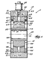
- Figure 1 is a sectional view of a bearing assembly incorporating various features of the invention.
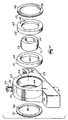
- Figure 2 is an exploded perspective view of a portion of the bearing assembly shown in Figure 1.
- Before one embodiment of the invention is explained in detail, it is to be understood that the invention is not limited in its application to the details of the construction and the arrangements of components set forth in the following description or illustrated in the drawings. The invention is capable of other embodiments and of being practiced or being carried out in various ways. Also, it is understood that the phraseology and terminology used herein is for the purpose of description and should not be regarded as limiting.
- Shown in the drawings is a bearing assembly 11 comprising an
outer non-rotating sub-assembly 13 and an inner rotatingsub-assembly 15. - The outer
non-rotating sub-assembly 13 includes an outer housing which, (while other constructions can be employed) in the disclosed construction, is in the form of apillow block housing 21 including an external surface having spacedside surface portions 23, a generally semi-cylindricalouter surface portion 25 extending between theside surface portions 23, and a cylindrical bore 27 having an axis 29 and extending between theside surface portions 23. - The
pillow block housing 21 also includes a lubrication conduit 31 communicating with the cylindrical bore 27, extending to the semi-cylindricalouter surface portion 25 of the external surface, and communicating with asuitable lubrication source 35. Thepillow block housing 21 can be formed in any suitable way from any suitable material. - The outer
non-rotating sub-assembly 13 also includes an outer bearing 41 which is located in the cylindrical bore 27 in thepillow block housing 21 and which includes an outercylindrical surface 43 engaging the cylindrical bore 27 of thepillow block housing 21, and a bore defined by an inwardly facing, spherically shaped, bearingsurface 45. - While other constructions can be employed, in the disclosed construction, the outer bearing 41 comprises first and second bearing
segments 51 and 53 which are axially spaced from each other to define therebetween aspace 55 which communicates with the lubrication conduit 31. The first bearing segment 51 includes an outer part orportion 61 providing a first portion of the cylindricalouter surface 43 of the outer bearing 41, and an inner part orportion 63 providing a first portion of the spherical inwardly facing,spherically shaped, bearingsurface 45 of the outer bearing 41. The second bearingsegment 53 includes an outer part orportion 65 providing a second portion of the cylindrical outer surface of the outer bearing, and an inner part orportion 67 providing a second portion of the inwardly facing, spherically shaped, bearingsurface 45 of the outer bearing 41. The first and second bearingsegments 51 and 53 are preferably of equal axial dimension between the opposing radial surfaces thereof. - While other constructions can be employed, in the disclosed construction, the
inner portions surfaces 45, of the first and second bearingsegments 51 and 53, are fabricated from a woven PTFE fabric, and theouter portions segments 51 and 53 are fabricated from a filament wound fiberglass and epoxy resin matrix and are respectively bonded to the inner parts orportions surface 45. - Preferably, the
outer bearing segments 51 and 53 are filament wound on a tooling ball which is much narrower than the inner race used in the mounted block. This method of manufacturing allows for more units to be wound at one time, allows for less material to be used in the process (less scrap), and eliminates the damaging of the inner race during the cut off process. - The inner rotating
sub-assembly 15 includes an inner bearing 71 including an outer surface defined by an outwardly facing, spherically shaped bearing surface 73 engaging the inwardly facing, spherically shaped, bearing surface portions of the first and secondouter bearing segments 51 and 53. The inner bearing 71 also includes an internalcylindrical bore 75. In addition, in the disclosed construction, the inner rotatingsub-assembly 15 includes aninner sleeve 81 having a cylindricalouter surface 83 received in the internalcylindrical bore 75 of theinner bearing 71, and aninternal bore 85 adapted to receive a rotating member 91 fixed to thesleeve 81 for common rotation therewith. - The inner bearing 71 can be fabricated from any suitable material and, in the disclosed construction, is preferably fabricated from steel. Any suitable construction can be employed for the
inner sleeve 81 and the rotating member 91. In some constructions, theinner sleeve 81 can be omitted and, in other instances, theinner sleeve 81 can constitute the rotating member 91. - The engagement between the outwardly facing, convexly formed, spherical bearing surface 73 of the
inner bearing 71 and the inwardly facing, concavely formed,spherical bearing surface 45 formed by the first and second outer bearing-segments 51 and 53 serves to retain the bearingsegments 51 and 53 in axially spaced relation to each other and to locate thespace 55 for communication with the lubrication conduit 31. In addition, thespace 55 is defined, in part, by the outwardly facing, convexly formed, spherical bearing surface 73 and, therefore, the spherical bearing surfaces 45 and 73 receive lubricant from thespace 55. - Means are provided for retaining the first and
second bearing segments 51 and 53 in spaced relation to each other and against axially outward movement relative to the inner bearing 41 and relative to thepillow block housing 21. While other constructions can be employed, in the disclosed construction, such means comprises the provision, in thepillow block housing 21, adjacent the opposite ends of the cylindrical bore 27 therein, of respective threadedportions 93, and the provision, at each end of the cylindrical bore 27, of respective covers orretainers 95 which are threadedly received by the threadedportions 93. While other constructions can be employed, in the disclosed construction, the covers orretainers 95 comprise annular washers having cylindrical outer edges oredge portions 97 threadedly received in the threadedportions 93 of thepillow block housing 21. In addition the covers, or retainers or washers include respectivecentral bores 99 with diameters greater than that of thespherical bearing surface 45 adjacent the outer ends thereof so as to engage the side surfaces of the bearingsegments 51 and 53 to prevent axial outward movement thereof. In addition to limiting axial movement of theouter bearing segments 51 and 53, the covers orretainers 95 also serve to enable adjustment for clearance and end play. - The disclosed bearing assembly construction improves reliability, life, and consistency of bearing operation under high loads and small angles of oscillation. In addition, the disclosed bearing assemblies also provide lower friction under boundary lubrication conditions.
- The disclosed bearing assembly construction also allows for the use of standard bearing blocks and seals for applications in dusty and dirty environments. In addition, the disclosed bearing assemblies can be run "dry", i.e., without lubrication, if the mating bearing surface engaging the bearing
segments 51 and 53 has the proper corrosion protection for the operating conditions. If desired, the life of the disclosed bearing assemblies can be extended by adding lubrication to the gap orspace 55 which is located between the bearingsegments 51 and 53 and which acts as a reservoir. - The disclosed bearing assembly construction also provides a major advantage in that the disclosed bearing assembly construction, as compared to a rolling element bearing, has the ability to withstand high loads with very small angles of oscillation without fretting, brinelling, spalling, galling, and fatigue of the mating surface.
Claims (8)
- A bearing assembly (11) comprising:- an outer non-rotating sub-assembly (13) including-- an outer housing (21) having a cylindrical bore (27), and-- an outer bearing (41) including an outer cylindrical surface (43) engaging said cylindrical bore (27) of said outer housing (21), and a bore defined by a spherical inwardly facing bearing surface (45), and- an inner movable sub-assembly (15) including-- an inner bearing (71) having an outer surface defined by a spherical outwardly facing bearing surface (73) engaging said spherical inwardly facing bearing surface (45) of said outer bearing (41), and-- an internal cylindrical bore (75), characterised in that- said internal cylindrical bore (75) is adapted to receive a movable member (81,91), and- said outer bearing (41) includes-- an outer bearing part (61,65) fabricated of filament wound fibreglass and epoxy resin matrix, and-- an inner bearing part (63, 67) fabricated of woven PTFE fabric.
- A bearing assembly according to Claim 1, characterised in that said inner movable sub-assembly (15) has the form of an inner rotatable sub-assembly comprising a sleeve (81) including a cylindrical outer surface (83) received in said internal cylindrical bore (75) of said inner bearing (71), and an internal bore (85) of said sleeve (81) is adapted to receive a rotating member (91) to be fixed thereto for common rotation therewith.
- A bearing assembly in accordance with Claim 1 or Claim 2, characterised in that- said outer bearing (41) includes-- a first bearing segment (51) including a first outer portion (61) and a first inner portion (63), and-- a second bearing segment (53) located in spaced relation to said first bearing segment (51) and including a second outer portion (65) and a second inner portion (67),- whereby said first and second outer portions (61, 65) provide respectively a first and second portion of said outer cylindrical surface (43), and- said first and second inner portion (63 and 67) provide respectively a first and second portion of said spherical inwardly facing bearing surface (45) of said outer bearing (41).
- A bearing assembly in accordance with Claim 3, characterised in that- said first and second bearing segments (51,53) define there between a space (55) extending to said spherical outwardly facing bearing surface (73) of said inner bearing (71), and- said outer housing (21) includes an external surface and a lubrication conduit (31) communicating between said space and said external surface.
- A bearing assembly in accordance with any one of the preceding Claims, characterised in that it comprises means (95) for preventing axial movement of said outer bearing (41) relative to said outer housing (21).
- A bearing assembly in accordance with any one of the preceding Claims, characterised in that- said cylindrical bore (27) of said outer housing (21) includes an axis (29) and axially spaced first and second ends (23), and- said bearing assembly further includes first and second covers (95) respectively fixed to said outer housing adjacent said first and second ends of said cylindrical bore (27) and in positions to close said cylindrical bore (27) and to prevent axial movement of said outer bearing (41) relative to said outer housing.
- A bearing assembly in accordance with Claim 6, characterised in that- said first and second ends (23) of said cylindrical bore (27) are threaded ends (93),- and said first and second covers (95) are annular members which are respectively threadedly engaged with said first and second threaded ends (93).
- A bearing assembly (11) according to claim 1, wherein- said outer housing comprises a pillow block housing (21) which includes an external surface (23, 25) and said cylindrical bore (27), first and second threaded ends (93), and a lubrication conduit (31) communicating between said external surface and said cylindrical bore,- said outer bearing (41) including-- a first bearing segment (51) including a first outer portion (61) and a first inner portion (63), and-- a second bearing segment (53) located in axially spaced relation to said first bearing segment to define there between a space (55) communicating with said lubrication conduit (31) and including a second outer portion (65) and a second inner portion (67),-- whereby said first and second outer portions (61, 65) provide respectively a first and second portion of said outer cylindrical surface (43) engaging said cylindrical bore (27), and-- said first and second inner portion (63 and 67) provide respectively a first and second portion of said spherical inwardly facing bearing surface (45),- said outer non-rotating sub-assembly (13) further includes first and second annular covers (95) respectively threadedly engaged with said first and second threaded ends (93) of said cylindrical bore and in positions to close said cylindrical bore and to prevent axial movement of said outer bearing (41) relative to said pillow block housing (21), and- said inner rotatable sub-assembly (15) includes a sleeve (81) including-- a cylindrical outer surface (83) received in said internal bore (75) of said inner bearing (71), and-- an internal bore (85) adapted to receive a rotatable member (91) to be fixed thereto for common rotation therewith.
Applications Claiming Priority (2)
| Application Number | Priority Date | Filing Date | Title |
|---|---|---|---|
| US90115 | 1998-06-04 | ||
| US09/090,115 US6004037A (en) | 1998-06-04 | 1998-06-04 | Bearing assembly with spherical bearing surfaces |
Publications (3)
| Publication Number | Publication Date |
|---|---|
| EP0962676A2 EP0962676A2 (en) | 1999-12-08 |
| EP0962676A3 EP0962676A3 (en) | 2000-11-29 |
| EP0962676B1 true EP0962676B1 (en) | 2006-01-25 |
Family
ID=22221393
Family Applications (1)
| Application Number | Title | Priority Date | Filing Date |
|---|---|---|---|
| EP99110521A Expired - Lifetime EP0962676B1 (en) | 1998-06-04 | 1999-06-01 | Bearing assembly with spherical bearing surfaces |
Country Status (5)
| Country | Link |
|---|---|
| US (1) | US6004037A (en) |
| EP (1) | EP0962676B1 (en) |
| JP (1) | JP2000009137A (en) |
| AT (1) | ATE316620T1 (en) |
| DE (1) | DE69929554T2 (en) |
Cited By (1)
| Publication number | Priority date | Publication date | Assignee | Title |
|---|---|---|---|---|
| EP3988807A1 (en) * | 2020-10-26 | 2022-04-27 | General Electric Company | Spherical journal bearing for a wind turbine drivetrain |
Families Citing this family (34)
| Publication number | Priority date | Publication date | Assignee | Title |
|---|---|---|---|---|
| US5989709A (en) * | 1998-04-30 | 1999-11-23 | Gore Enterprises Holdings, Inc. | Polytetrafluoroethylene fiber |
| US6623238B2 (en) | 1998-08-21 | 2003-09-23 | Honeywell International, Inc. | Air turbine starter with seal assembly |
| JP2001193734A (en) | 2000-01-05 | 2001-07-17 | Minebea Co Ltd | Fixing method for spherical slide bearing |
| JP2001193735A (en) * | 2000-01-05 | 2001-07-17 | Minebea Co Ltd | Torque adjusting mechanism for spherical slide bearing |
| FR2833572B1 (en) * | 2001-12-18 | 2004-04-02 | Airbus France | METHOD AND DEVICE FOR MOUNTING A LANDING GEAR ON AN AIRCRAFT STRUCTURE AND AIRCRAFT COMPRISING SUCH A TRAIN |
| US6681579B2 (en) | 2002-02-07 | 2004-01-27 | Honeywell International, Inc. | Air turbine starter with fluid flow control |
| US6860638B2 (en) * | 2002-03-04 | 2005-03-01 | Polygon Company, Inc. | Spherical bearing |
| US7396017B2 (en) * | 2002-06-21 | 2008-07-08 | Isotech Of Illinois, Inc. | Shaft seal assembly |
| US7090403B2 (en) * | 2002-06-21 | 2006-08-15 | Isotech Of Illinois, Inc. | Articulated seal |
| US7726661B2 (en) * | 2002-06-21 | 2010-06-01 | Inpro/Seal Llc | Pressure balanced shaft seal assembly |
| US8979093B2 (en) * | 2002-06-21 | 2015-03-17 | Inpro/Seal, LLC | Pressure balanced shaft seal assembly |
| US9004491B2 (en) | 2002-06-21 | 2015-04-14 | Inpro/Seal Llc | Shaft seal assembly |
| US7010721B2 (en) * | 2003-09-29 | 2006-03-07 | International Business Machines Corporation | File system journal management |
| US7172352B2 (en) * | 2003-12-09 | 2007-02-06 | Hewlett-Packard Development Company, L.P. | Bearing |
| US7033133B2 (en) | 2003-12-10 | 2006-04-25 | Honeywell International, Inc. | Air turbine starter having a low differential check valve |
| US7033134B2 (en) | 2004-02-24 | 2006-04-25 | Honeywell International, Inc. | Air turbine starter having a force balanced, pressure energized, weighted check valve |
| US7014419B2 (en) * | 2004-02-27 | 2006-03-21 | Honeywell International, Inc. | Passive improved air turbine starter lubrication system |
| DE102004062842B3 (en) * | 2004-12-27 | 2006-04-27 | Ab Skf | Gripper shaft`s bearing arrangement for printing machine, has slide bearing with two rings, in which one ring is divided in two parts, and lubricant storing unit made of porous polymer material and arranged between two parts of ring |
| US7461902B1 (en) | 2005-10-26 | 2008-12-09 | Robert Darst | Auger car bearing support |
| KR100752619B1 (en) | 2005-11-03 | 2007-08-29 | 주식회사 동아오토모티브 | Pillow Ball Joint Integrally Incorporating Knuckle |
| BE1017140A3 (en) * | 2006-05-15 | 2008-03-04 | Hansen Transmissions Int | PRESSER COMB FOR A GEAR GEAR TRANSMISSION. |
| WO2008008471A1 (en) * | 2006-07-13 | 2008-01-17 | Roller Bearing Company Of America, Inc. | Hybrid spherical bearing |
| US7828482B2 (en) * | 2006-08-28 | 2010-11-09 | Roller Bearing Company Of America, Inc. | Tungsten carbide enhanced bearing |
| US20080304902A1 (en) * | 2006-11-01 | 2008-12-11 | Tomasz Buchner | Ball joint |
| US20100264600A1 (en) * | 2009-04-21 | 2010-10-21 | Richard Lee Willms | Pneumatic mechanical seal |
| US8393796B2 (en) * | 2010-07-29 | 2013-03-12 | Ontario Drive & Gear Limited | Heavy duty bearing support system for ATV |
| US8500333B2 (en) * | 2011-05-24 | 2013-08-06 | Siemens Industry, Inc. | Self aligning oil film bearing |
| ITBO20110534A1 (en) * | 2011-09-16 | 2013-03-17 | Wam Ind Spa | INTERMEDIATE SUPPORT ELEMENT FOR AN AUGER |
| WO2013103732A2 (en) | 2012-01-03 | 2013-07-11 | New Way Machine Components, Inc. | Air bearing for use as seal |
| US10598222B2 (en) | 2012-01-03 | 2020-03-24 | New Way Machine Components, Inc. | Air bearing for use as seal |
| TW201530025A (en) * | 2013-09-30 | 2015-08-01 | Inpro Seal Llc | Shaft seal assembly |
| TWI735960B (en) * | 2018-09-28 | 2021-08-11 | 美商英普羅密封有限責任公司 | Shaft seal assembly |
| CN109340268A (en) * | 2018-10-31 | 2019-02-15 | 中船动力研究院有限公司 | A kind of bearing support assembly |
| DE102020111280A1 (en) | 2020-04-24 | 2021-10-28 | THK RHYTHM AUTOMOTIVE GmbH | Ball stud and method for producing a ball stud |
Family Cites Families (14)
| Publication number | Priority date | Publication date | Assignee | Title |
|---|---|---|---|---|
| FR1053655A (en) * | 1952-04-10 | 1954-02-04 | Improvements to spherical bearings | |
| FR68461E (en) * | 1954-06-04 | 1958-04-30 | Soulard Charles Georges | Advanced bearing |
| US2906568A (en) * | 1956-03-13 | 1959-09-29 | Lockheed Aircraft Corp | Spherical bearing |
| DE1952621U (en) * | 1966-10-27 | 1966-12-29 | Artur Seyfert K G Kugellagerfa | ARTICULATED ROD END. |
| US3974009A (en) * | 1969-05-21 | 1976-08-10 | Rex Chainbelt Inc. | Method for making ball and socket type bearings in multiple |
| US3700295A (en) * | 1971-12-03 | 1972-10-24 | Rex Chainbelt Inc | Ball and socket bearing |
| US4213512A (en) * | 1978-05-08 | 1980-07-22 | Dana Corporation | Power shaft support bearing |
| DE2915088C2 (en) * | 1979-04-12 | 1982-09-09 | Industrieanlagen-Betriebsgesellschaft Mbh, 8012 Ottobrunn | Ball joint bearings |
| DE4216559C2 (en) * | 1992-05-20 | 1995-05-24 | Freudenberg Carl Fa | Swivel bearing |
| US5288354A (en) * | 1992-08-26 | 1994-02-22 | Rexnord Corporation | Method of bonding self-lubricating fibers to an external surface of a substratum |
| US5265965A (en) * | 1992-09-02 | 1993-11-30 | Rexnord Corporation | Composite ball and socket bearing with convex outer surface |
| DE69401389T2 (en) * | 1993-06-30 | 1997-07-10 | Torrington Co | Spherical bearing and assembly process |
| US5549393A (en) * | 1995-01-09 | 1996-08-27 | Alphatech, Inc. | Self-aligning bearing for high temperature applications |
| US5725315A (en) * | 1996-06-03 | 1998-03-10 | Caterpillar Inc. | Shaft supporting bearing arrangement |
-
1998
- 1998-06-04 US US09/090,115 patent/US6004037A/en not_active Expired - Lifetime
-
1999
- 1999-06-01 AT AT99110521T patent/ATE316620T1/en not_active IP Right Cessation
- 1999-06-01 EP EP99110521A patent/EP0962676B1/en not_active Expired - Lifetime
- 1999-06-01 DE DE69929554T patent/DE69929554T2/en not_active Expired - Lifetime
- 1999-06-02 JP JP11154697A patent/JP2000009137A/en active Pending
Cited By (2)
| Publication number | Priority date | Publication date | Assignee | Title |
|---|---|---|---|---|
| EP3988807A1 (en) * | 2020-10-26 | 2022-04-27 | General Electric Company | Spherical journal bearing for a wind turbine drivetrain |
| US11614078B2 (en) | 2020-10-26 | 2023-03-28 | General Electric Company | Spherical journal bearing for a wind turbine drivetrain |
Also Published As
| Publication number | Publication date |
|---|---|
| EP0962676A3 (en) | 2000-11-29 |
| DE69929554D1 (en) | 2006-04-13 |
| ATE316620T1 (en) | 2006-02-15 |
| DE69929554T2 (en) | 2006-11-09 |
| JP2000009137A (en) | 2000-01-11 |
| US6004037A (en) | 1999-12-21 |
| EP0962676A2 (en) | 1999-12-08 |
Similar Documents
| Publication | Publication Date | Title |
|---|---|---|
| EP0962676B1 (en) | Bearing assembly with spherical bearing surfaces | |
| CA2214939C (en) | Full perimeter fiber wound bearing construction | |
| US4765757A (en) | Self-aligning spherical bushing means | |
| CA2208064C (en) | Self-aligning bearing for high temperature applications | |
| EP0377523B1 (en) | Bearing liner | |
| US5219231A (en) | Split race bearing assemblies | |
| US5677584A (en) | Bearing assembly for dynamoelectric machines | |
| CA1180742A (en) | Self-adjusting angular contact spherical bearing | |
| EP0631060B1 (en) | A sheet metal bearing for an electric motor | |
| GB2265950A (en) | Bearings. | |
| US5463811A (en) | Spherical bearing and method of assembling a spherical bearing | |
| EP3742013A1 (en) | Electrically conductive and self-lubricating bearing liner, bearing containing the same, and method of manufacturing such a bearing liner | |
| CA1332624C (en) | Bearings and bearing assemblies | |
| US3888554A (en) | Self lubricating spherical bearing assembly | |
| US6799894B2 (en) | Bushing | |
| US5947496A (en) | Low lash idler arm assembly | |
| US9765808B2 (en) | Self-lubricating oscillating pin joint | |
| US5468074A (en) | Bearing assembly | |
| US5845998A (en) | Ball bearing assembly with polymer bearing ring | |
| US2464492A (en) | Self-aligning bearing | |
| JP2003247540A (en) | Rolling bearing and rod end bearing | |
| US3746410A (en) | Journal bearing | |
| JPH0461970B2 (en) | ||
| US20190242430A1 (en) | Bearing system with self-lubrication features, seals, grooves and slots for maintenance-free operation | |
| CN218325805U (en) | Angular contact radial spherical plain bearing |
Legal Events
| Date | Code | Title | Description |
|---|---|---|---|
| PUAI | Public reference made under article 153(3) epc to a published international application that has entered the european phase |
Free format text: ORIGINAL CODE: 0009012 |
|
| AK | Designated contracting states |
Kind code of ref document: A2 Designated state(s): AT DE FR GB IT |
|
| AX | Request for extension of the european patent |
Free format text: AL;LT;LV;MK;RO;SI |
|
| PUAL | Search report despatched |
Free format text: ORIGINAL CODE: 0009013 |
|
| AK | Designated contracting states |
Kind code of ref document: A3 Designated state(s): AT BE CH CY DE DK ES FI FR GB GR IE IT LI LU MC NL PT SE |
|
| AX | Request for extension of the european patent |
Free format text: AL;LT;LV;MK;RO;SI |
|
| RIC1 | Information provided on ipc code assigned before grant |
Free format text: 7F 16C 35/02 A, 7F 16C 23/04 B |
|
| 17P | Request for examination filed |
Effective date: 20010529 |
|
| AKX | Designation fees paid |
Free format text: AT DE FR GB IT |
|
| 17Q | First examination report despatched |
Effective date: 20040122 |
|
| GRAP | Despatch of communication of intention to grant a patent |
Free format text: ORIGINAL CODE: EPIDOSNIGR1 |
|
| GRAS | Grant fee paid |
Free format text: ORIGINAL CODE: EPIDOSNIGR3 |
|
| GRAA | (expected) grant |
Free format text: ORIGINAL CODE: 0009210 |
|
| AK | Designated contracting states |
Kind code of ref document: B1 Designated state(s): AT DE FR GB IT |
|
| PG25 | Lapsed in a contracting state [announced via postgrant information from national office to epo] |
Ref country code: AT Free format text: LAPSE BECAUSE OF FAILURE TO SUBMIT A TRANSLATION OF THE DESCRIPTION OR TO PAY THE FEE WITHIN THE PRESCRIBED TIME-LIMIT Effective date: 20060125 |
|
| REG | Reference to a national code |
Ref country code: GB Ref legal event code: FG4D |
|
| REF | Corresponds to: |
Ref document number: 69929554 Country of ref document: DE Date of ref document: 20060413 Kind code of ref document: P |
|
| ET | Fr: translation filed | ||
| PLBE | No opposition filed within time limit |
Free format text: ORIGINAL CODE: 0009261 |
|
| STAA | Information on the status of an ep patent application or granted ep patent |
Free format text: STATUS: NO OPPOSITION FILED WITHIN TIME LIMIT |
|
| 26N | No opposition filed |
Effective date: 20061026 |
|
| REG | Reference to a national code |
Ref country code: HK Ref legal event code: WD Ref document number: 1024286 Country of ref document: HK |
|
| REG | Reference to a national code |
Ref country code: FR Ref legal event code: PLFP Year of fee payment: 18 |
|
| REG | Reference to a national code |
Ref country code: FR Ref legal event code: PLFP Year of fee payment: 19 |
|
| REG | Reference to a national code |
Ref country code: FR Ref legal event code: PLFP Year of fee payment: 20 |
|
| PGFP | Annual fee paid to national office [announced via postgrant information from national office to epo] |
Ref country code: FR Payment date: 20180626 Year of fee payment: 20 |
|
| PGFP | Annual fee paid to national office [announced via postgrant information from national office to epo] |
Ref country code: DE Payment date: 20180627 Year of fee payment: 20 Ref country code: GB Payment date: 20180627 Year of fee payment: 20 Ref country code: IT Payment date: 20180621 Year of fee payment: 20 |
|
| REG | Reference to a national code |
Ref country code: DE Ref legal event code: R071 Ref document number: 69929554 Country of ref document: DE |
|
| REG | Reference to a national code |
Ref country code: GB Ref legal event code: PE20 Expiry date: 20190531 |
|
| PG25 | Lapsed in a contracting state [announced via postgrant information from national office to epo] |
Ref country code: GB Free format text: LAPSE BECAUSE OF EXPIRATION OF PROTECTION Effective date: 20190531 |