EP0961785B1 - Reglage ameliore de la taille des gouttelettes d'un catalyseur en solution par une buse de pulverisation perpendiculaire - Google Patents
Reglage ameliore de la taille des gouttelettes d'un catalyseur en solution par une buse de pulverisation perpendiculaire Download PDFInfo
- Publication number
- EP0961785B1 EP0961785B1 EP98906546A EP98906546A EP0961785B1 EP 0961785 B1 EP0961785 B1 EP 0961785B1 EP 98906546 A EP98906546 A EP 98906546A EP 98906546 A EP98906546 A EP 98906546A EP 0961785 B1 EP0961785 B1 EP 0961785B1
- Authority
- EP
- European Patent Office
- Prior art keywords
- catalyst
- liquid
- gas
- nozzle
- reactor
- Prior art date
- Legal status (The legal status is an assumption and is not a legal conclusion. Google has not performed a legal analysis and makes no representation as to the accuracy of the status listed.)
- Expired - Lifetime
Links
Images

Classifications
-
- B—PERFORMING OPERATIONS; TRANSPORTING
- B01—PHYSICAL OR CHEMICAL PROCESSES OR APPARATUS IN GENERAL
- B01J—CHEMICAL OR PHYSICAL PROCESSES, e.g. CATALYSIS OR COLLOID CHEMISTRY; THEIR RELEVANT APPARATUS
- B01J4/00—Feed or outlet devices; Feed or outlet control devices
- B01J4/001—Feed or outlet devices as such, e.g. feeding tubes
- B01J4/002—Nozzle-type elements
-
- B—PERFORMING OPERATIONS; TRANSPORTING
- B01—PHYSICAL OR CHEMICAL PROCESSES OR APPARATUS IN GENERAL
- B01J—CHEMICAL OR PHYSICAL PROCESSES, e.g. CATALYSIS OR COLLOID CHEMISTRY; THEIR RELEVANT APPARATUS
- B01J19/00—Chemical, physical or physico-chemical processes in general; Their relevant apparatus
- B01J19/26—Nozzle-type reactors, i.e. the distribution of the initial reactants within the reactor is effected by their introduction or injection through nozzles
-
- B—PERFORMING OPERATIONS; TRANSPORTING
- B01—PHYSICAL OR CHEMICAL PROCESSES OR APPARATUS IN GENERAL
- B01J—CHEMICAL OR PHYSICAL PROCESSES, e.g. CATALYSIS OR COLLOID CHEMISTRY; THEIR RELEVANT APPARATUS
- B01J8/00—Chemical or physical processes in general, conducted in the presence of fluids and solid particles; Apparatus for such processes
- B01J8/0015—Feeding of the particles in the reactor; Evacuation of the particles out of the reactor
-
- B—PERFORMING OPERATIONS; TRANSPORTING
- B01—PHYSICAL OR CHEMICAL PROCESSES OR APPARATUS IN GENERAL
- B01J—CHEMICAL OR PHYSICAL PROCESSES, e.g. CATALYSIS OR COLLOID CHEMISTRY; THEIR RELEVANT APPARATUS
- B01J8/00—Chemical or physical processes in general, conducted in the presence of fluids and solid particles; Apparatus for such processes
- B01J8/18—Chemical or physical processes in general, conducted in the presence of fluids and solid particles; Apparatus for such processes with fluidised particles
- B01J8/1818—Feeding of the fluidising gas
- B01J8/1827—Feeding of the fluidising gas the fluidising gas being a reactant
-
- B—PERFORMING OPERATIONS; TRANSPORTING
- B05—SPRAYING OR ATOMISING IN GENERAL; APPLYING FLUENT MATERIALS TO SURFACES, IN GENERAL
- B05B—SPRAYING APPARATUS; ATOMISING APPARATUS; NOZZLES
- B05B7/00—Spraying apparatus for discharge of liquids or other fluent materials from two or more sources, e.g. of liquid and air, of powder and gas
- B05B7/02—Spray pistols; Apparatus for discharge
- B05B7/04—Spray pistols; Apparatus for discharge with arrangements for mixing liquids or other fluent materials before discharge
- B05B7/0416—Spray pistols; Apparatus for discharge with arrangements for mixing liquids or other fluent materials before discharge with arrangements for mixing one gas and one liquid
- B05B7/0433—Spray pistols; Apparatus for discharge with arrangements for mixing liquids or other fluent materials before discharge with arrangements for mixing one gas and one liquid with one inner conduit of gas surrounded by an external conduit of liquid upstream the mixing chamber
-
- B—PERFORMING OPERATIONS; TRANSPORTING
- B05—SPRAYING OR ATOMISING IN GENERAL; APPLYING FLUENT MATERIALS TO SURFACES, IN GENERAL
- B05B—SPRAYING APPARATUS; ATOMISING APPARATUS; NOZZLES
- B05B7/00—Spraying apparatus for discharge of liquids or other fluent materials from two or more sources, e.g. of liquid and air, of powder and gas
- B05B7/02—Spray pistols; Apparatus for discharge
- B05B7/08—Spray pistols; Apparatus for discharge with separate outlet orifices, e.g. to form parallel jets, i.e. the axis of the jets being parallel, to form intersecting jets, i.e. the axis of the jets converging but not necessarily intersecting at a point
-
- C—CHEMISTRY; METALLURGY
- C08—ORGANIC MACROMOLECULAR COMPOUNDS; THEIR PREPARATION OR CHEMICAL WORKING-UP; COMPOSITIONS BASED THEREON
- C08F—MACROMOLECULAR COMPOUNDS OBTAINED BY REACTIONS ONLY INVOLVING CARBON-TO-CARBON UNSATURATED BONDS
- C08F10/00—Homopolymers and copolymers of unsaturated aliphatic hydrocarbons having only one carbon-to-carbon double bond
-
- C—CHEMISTRY; METALLURGY
- C08—ORGANIC MACROMOLECULAR COMPOUNDS; THEIR PREPARATION OR CHEMICAL WORKING-UP; COMPOSITIONS BASED THEREON
- C08F—MACROMOLECULAR COMPOUNDS OBTAINED BY REACTIONS ONLY INVOLVING CARBON-TO-CARBON UNSATURATED BONDS
- C08F210/00—Copolymers of unsaturated aliphatic hydrocarbons having only one carbon-to-carbon double bond
- C08F210/16—Copolymers of ethene with alpha-alkenes, e.g. EP rubbers
Definitions
- a method of controlling the size of drops of liquid catalyst entering a gas phase polymerization reactor is taught herein to prevent the formation of large flaky particles which might result from the use of liquid catalysts. Said control is affected by using a perpendicular spray nozzle which produces fine catalyst droplet dispersion, resulting in small spherical primary particles and small particle agglomerates.
- U.S. Patent No. 5,317,036 teaches the gas-phase polymerization of olefins with catalysts in liquid form.
- resin particle size can be controlled by spraying the liquid catalyst into a zone which is substantially free of resin as disclosed in US 5 698 727. This process allows a brief period of time for the spray droplets to undergo evaporation and polymerization before contacting the polymer particles already in the reactor, thus reducing the tendency for the droplets to adhere to the already formed particles.
- the "particle-lean" zone preferably is created by feeding a jet of heated monomer or cycle gas into the side of the reactor.
- a first aspect of the invention is defined in claim 1.
- a second aspect of the invention is defined in claim 11.
- the large hollow clusters of polymer which may be produced when using a catalyst in a liquid form in a gas phase polymerization reactor result from large droplets of the catalyst, which are either formed in the injection tube or during coalescence in the liquid spray. Either in flight, or upon contact with resin in the reactor, these large droplets contact a large number of small droplets or particles which adhere to the droplet surface
- the solvent, if any, in the catalyst droplet evaporates, depositing the catalyst on the inside surface of the spherical cluster. This deposited catalyst aids polymerization at this site and thereby cements the small particles onto the surface of the expanding spherical cluster, which can eventually break open producing a flaky structure.
- the prevention of the formation of these large catalyst droplets is believed to provide a solution to the excessive resin agglomeration and flaking problem.
- a perpendicular spray nozzle produces a fine droplet dispersion, resulting in small spherical primary particles and in clusters of small particles.
- the perpendicular spray nozzles improve the dispersion of the droplets into the monomer and cycle gas jets around the nozzle. It is helpful to locate solution spray nozzles in a jet of either recycle gas or monomer, or a combination of both as disclosed in US 5 698 727. These gas streams allow the droplets to dry and polymerize somewhat before contacting the resin in the reactor, thus reducing agglomeration.
- the catalyst spray is delivered colinearly within the gas jets, the high velocities used for these gas jets narrows the spray angle.
- Perpendicular spray nozzles reduce this tendency by spraying the catalyst solution over a wider area and into a higher volume of cycle gas or monomer.
- the liquid may be atomized with an inert carrier gas, as is done with the gas-assisted perpendicular spray nozzle (As shown in Figure 1).
- a perpendicular pressure nozzle could be used to deliver a perpendicular spray of high-pressure catalyst liquid in the absence of an atomizing gas.
- the perpendicular feeding geometry can be used with effervescent gas-liquid contact in the spraying nozzle or with an ultrasonic nozzle.
- the invention described herein could also be applied to other known atomization devices, such as electrostatic, sonic-whistle, or rotary, etc. nozzles.
- perpendicular spray nozzle refers to a tube for delivering a liquid wherein there is an inlet end for the input of the liquid, and optionally, a gas.
- the other end of the tube i.e., "distal end" wherein there is at least one exit hole (orifice) which is at more than 45°, and most preferably 60 to 90°, off from the direction of flow of the liquid within the nozzle (i.e., from the central axis of the tube), where the orifice is located towards the distal end of the nozzle.
- Said nozzles may have any number of orifices and may include a gas stream within the liquid stream. There is no need for a separate mixing chamber for the gas and liquid within the nozzle.
- perpendicular spray nozzles require less inert gas to atomize a given amount of catalyst solution than does an injection tube.
- the desired droplet size is achieved herein by gas to liquid mass flow ratios of between about 3:1 and 0.5:1 and more preferably between about 2:1 and 1:1.
- the amount of inert gas required to atomize 9.1 kg/hr of liquid with the perpendicular spray nozzle, the perpendicular effervescent nozzle, and a 0.30-cm ID injection tube are shown in Table 1. For these examples liquid with a viscosity of 0.002 g / cm s was sprayed at a pressure of 1962 kPa.
- Nozzle Inert gas requirement Direction of Spray Average Droplet Size (mm) 0.30 cm ID injection tube 45.4 kg/hr Colinear 0.10 Perpendicular spray nozzle 13.6 kg/hr Perpendicular 0.045 Perpendicular effervescent 6.8 kg/hr Perpendicular 0.025
- the table shows that with the perpendicular spray nozzle, a fine droplet size of 0.045 mm can be achieved at a gas to liquid mass flow ratio of about 1.5:1.
- the droplet size is a function of the atomization gas flowrate, the total liquid flowrate, and the liquid properties of viscosity, density and surface tension.
- the flowrate of atomization gas has the strongest influence on the droplet size, for the exemplary nozzle described below.
- the droplet size distributions from a perpendicular spray nozzle were measured with an imaging system on a spray of 9.1 kg/hr of catalyst solvent in an off-line reactor at a pressure of 1962 kPa. The average droplet size was found to decrease rapidly with increasing nitrogen flow as shown in Figure 3.
- Actual catalyst drop particle size may also be controlled through the use of a dilation control device on the orifice.
- a dilation control device on the orifice.
- Such a device would allow expanding or contracting the orifice size to regulate drop size.
- Said control may be effected in-line and/or automatically.
- the ultimate resin particle size is determined by the initial catalyst droplet size, the amount of catalyst in a droplet, and by the degree of agglomeration between the new droplets and resin particles in the reactor.
- the droplet size is governed primarily by the flow rate or velocity of the atomizing gas.
- the amount of catalyst in a droplet is governed by the amount of diluent added to the liquid catalyst stream and by the droplet size.
- the degree of agglomeration between new droplets and particles can be influence by the droplet size, the amount of catalyst in the particle, the catalyst activity and kinetic behavior, and the evaporation rate of the droplet solvent(s).
- the liquid stream consists of the catalyst, the cocatalyst, optional activators, and optionally, a diluent.
- the total liquid rate is adjusted by changing the amount of diluent added to the steady flow of catalyst and cocatalyst necessary to maintain a constant polymerization rate.
- an increase in total liquid flow results in the formation of more droplets of similar size and decreased catalyst content.
- the final resin particle size can be controlled.
- An increase in the atomization rate decreases the particle size and decreases the resin average particle size (APS).
- the total liquid rate can be changed to either increase or decrease the final resin property size.
- the diluent flow can reduce the amount of catalyst in each droplet, preventing overheating and agglomeration.
- the particle size can be controlled by adjusting the amount of diluent fed with the catalyst, illustrated in Figure 4. If too much diluent is added, the reactor dew point is increased and the catalyst activity per volume of droplet is low. These factors slow the evaporation rate from the droplets so that the overall particle size may be too large (to the right of point D). Under cases of high activity, low dew point, and concentrated catalyst solution (to the left of A), the particles can overheat and fuse together.
- a change in the amount of diluent fed with the catalyst can shift the resin average particle size (APS) into a desirable range.
- the opposite can also occur, that is, changes in catalyst dilution can improve a very small APS to an acceptable range (movement out of the small APS and into the desired AB or CD ranges.)
- the amount of diluent fed with the catalyst and the amount of diluent vapor in the process cycle gas can be varied independently. Often, an additional stream of the solvent used to dilute the catalyst and cocatalyst can be fed directly to the process as an induced condensing agent. In this way the relative rate of solvent evaporation can be controlled by adjusting the amount of solvent vapor in the cycle gas. When the level of induced condensing agent is increased in the cycle gas, the evaporation rate of the droplets can decrease, which can lead to increased particle size under some conditions.
- the amount of solvent in the droplets can be decreased by feeding less solvent with the catalyst, and the droplet size can be decreased by feeding more atomization gas, in this way the droplets can form new stable particles more readily under the conditions of increased dew point or condensation in the cycle gas.
- the perpendicular spray nozzle can produce catalyst droplets of a desired average size (0.005 to 0.150 mm) within a narrow size distribution.
- the droplet size can be adjusted without disturbing the ongoing polymerization reaction by regulating liquid and gas flow rates.
- a narrow distribution of droplet size from about 0.005 to about 0.150 mm, preferably about 0.010 to 0.0750 mm, can prevent the formation of large agglomerates resulting from large droplets and the formation of fines resulting from small droplets.
- this drop size/flow rate model may be operationally linked (via computer, live operator or other means) to specific reactor conditions and controls, which would allow control of the catalyst drop size in relation to polymer particle size in the reactor.
- the polymer bulk density is known to decrease in the presence of the undesired larger particles. With bulk density fluctuations there are commensurate changes in the bed level and the breadth of the fluidization bands depicting the oscillations of the bed. If the polymer particles are too small, they tend to accumulate in the top of the reactor and can be discerned by detecting changes of the fluidized bulk density, bed level and high bed level.
- liquid and gas flows or even orifice size in the nozzle to adjust the particles to within a desired range to maintain the resin size during the course of polymerization.
- control may be accomplished separately from catalyst flow rate if a liquid diluent is used for the catalyst, i.e., the diluent level may be controlled separately from the catalyst feed rate. As can be understood by one of skill in the art, this may be done using automated control technology.
- Additional control of average particle size may be achieved by using multiple perpendicular spray nozzles or a combination of perpendicular spray and other atomization devices, each creating a unique droplet size.
- the relative catalyst feedrates then can be changed to control the overall average particle size.
- multiple nozzles could be used to spray different catalysts, of differing solvent compatibilities and particle formation tendencies, to produce polymers of broad or bimodal molecular weight and comonomer distributions in a single reactor.
- Catalyst Any type of polymerization catalyst may be used in the present process, provided it is stable and sprayable or atomizable when in liquid form. A single liquid catalyst may be used, or a liquid mixture of catalysts may be employed if desired. A dispersion of slurry of supported catalysts may also be used. These catalysts are used with cocatalysts and promoters well known in the art. Examples of suitable catalysts include:
- catalyst compositions comprising a metallocene catalyst in liquid form and an activating cocatalyst.
- the practice of this invention is not limited to any particular class or kind of metallocene catalyst.
- the catalyst composition may comprise any unsupported metallocene catalyst useful in slurry, solution, bulk, or gas phase olefin polymerization.
- One or more than one metallocene catalyst may be employed.
- at least two metallocene catalysts may be used in a single catalyst composition to achieve a broadened molecular weight distribution polymer product.
- Metallocene catalysts are organometallic coordination complexes of one or more ⁇ -bonded moieties in association with a metal atom from Groups IIIB to VIII or the rare earth metals of the Periodic Table.
- Bridged and unbridged mono-, bis-, and tris-cycloalkadienyl/metal compounds are the most common metallocene catalysts, and generally are of the formula: (L) y R 1 z (L')MX (x-y-1) wherein M is a metal from groups IIIB to VIII of the Periodic Table; L and L' are the same or different and are p-bonded ligands coordinated to M, preferably cycloalkadienyl groups such as cyclopentadienyl, indenyl, or fluorenyl groups optionally substituted with one or more hydrocarbyl groups containing 1 to 20 carbon atoms; R 1 is a C 1 -C 4 substituted or unsubstituted alkylene radical, a dialkyl or diaryl germanium or silicon, or an alkyl or aryl phosphine or amine radical bridging L and L'; each X is independently hydrogen, an aryl, alkyl, alkenyl, al
- metallocene catalysts represented by formula II are dialkyl metallocenes such as bis(cyclopentadienyl)titanium dimethyl, bis(cyclopentadienyl)titanium diphenyl, bis(cyclopentadienyl)zirconium dimethyl, bis(cyclopentadienyl)zirconium diphenyl, bis(cyclopentadienyl)hafnium methyl and diphenyl, bis(cyclopentadienyl)titanium di-neopentyl, bis(cyclopentadienyl)zirconium di-neopentyl, bis(cyclopentadienyl)titanium dibenzyl, bis(cyclopentadienyl)zirconium dibenzyl, bis(cyclopentadienyl)vanadium dimethyl; mono alkyl metallocenes such as bis(cyclopentadienyl)titanium dimethyl,
- Particularly preferred metallocene catalysts have one of the following formulas (III or IV): or wherein:
- the supportive substituent formed by Q, Y and Z is a unicharged polydentate ligand exerting electronic effects due to its high polarizability, similar to the cyclopentadienyl group.
- the disubstituted carbamates, and the carboxylates are employed.
- metallocene catalysts according to formulas III and IV include indenyl zirconium tris(diethylcarbamate), indenyl zirconium tris(pivalatc), indenyl zirconium tris(p-toluate), indenyl zirconium trio(benzoate), (1-methylindenyl) zirconium tris(pivalate), (2-methylindenyl) zirconium tris(diethylcarbamate), (methylcyclopentadienyl) zirconium tris(pivalate), cyclopentadienyl tris(pivalate), and (pentamethylcyclopentadienyl) zirconium tris(benzoate).
- Preferred examples of these metallocene catalysts are indenyl zirconium tris(diethylcarbamate) and indenyl zirconium tris(pivalate).
- metallocene catalyst that can be used in accordance with the invention is a constrained geometry catalyst of the formula: wherein:
- Constrained geometry catalysts are well known to those skilled in the art and are disclosed in, for example, U.S. Patent Nos. 5,026,798 and 5,055,438 and published European Application No. 0 416 815 A2.
- substituents Z', Cp, Y', X' and M in formula V are: Z' Cp Y' X' M dimethylsilyl cyclopentadienyl t-butylamido chloride titanium methylphenylsilyl fluorenyl phenylamido methyl zirconium diphenylsilyl indenyl cyclohexylamido hafnium tetramethylethylene oxo ethylene tetramethylcyclopentadienyl diphenylmethylene
- the invention is also useful with another class of single site catalyst precursors, di(imine) metal complexes, as described in PCT Application No. WO 96/23010, which is incorporated herein by reference.
- the activating cocatalyst is capable of activating the metallocene catalyst.
- the activating cocatalyst is one of the following: (a) branched or cyclic oligomeric poly(hydrocarbyl-aluminum oxide)s which contain repeating units of the general formula -(Al(R*)O)-, where R* is hydrogen, an alkyl radical containing from 1 to about 12 carbon atoms, or an aryl radical such as a substituted or unsubstituted phenyl or naphthyl group; (b) ionic salts of the general formula [A + ] ⁇ [BR** 4 - ], where A + is a cationic Lewis or Bronsted acid capable of abstracting an alkyl, halogen, or hydrogen from the metallocene catalysts, B is boron, and R** is a substituted aromatic hydrocarbon, preferably a perfluorophenyl radical; and (c) boron alkyls of the general formula
- the activating cocatalyst is an aluminoxane such as methylaluminoxane (MAO) or modified methylaluminoxane (MMAO), or a boron alkyl.
- aluminoxane such as methylaluminoxane (MAO) or modified methylaluminoxane (MMAO), or a boron alkyl.
- Aluminoxanes are preferred and their method of preparation is well known in the art.
- Aluminoxanes may be in the form of oligomeric linear alkyl aluminoxanes represented by the formula: or oligomeric cyclic alkyl aluminoxanes of the formula: wherein s is 1-40, preferably 10-20; p is 3-40, preferably 3-20; and R*** is an alkyl group containing 1 to 12 carbon atoms, preferably methyl or an aryl radical such as a substituted or unsubstituted phenyl or naphthyl radical.
- R*** is methyl
- MMAO R*** is a mixture of methyl and C2 to C12 alkyl groups wherein methyl comprises about 20 to 80 percent by weight of the R*** group.
- the amount of activating cocatalyst and metallocene catalyst usefully employed in preparation of the catalyst composition can vary over a wide range.
- the cocatalyst is a branched or cyclic oligomeric poly(hydrocarbylaluminum oxide)
- the mole ratio of aluminum atoms contained in the poly(hydrocarbylaluminum oxide) to metal atoms contained in the metallocene catalyst is generally in the range of from about 2:1 to about 100,000:1, preferably in the range of from about 10:1 to about 10,000:1, and most preferably in the range of from about 50:1 to about 2,000:1.
- the mole ratio of boron atoms contained in the ionic salt or the boron alkyl to metal atoms contained in the metallocene catalyst is generally in the range of from about 0.5:1 to about 10:1, preferably in the range of from about 1:1 to about 5:1.
- the liquid catalyst can be composed of one or more of metal compounds in combination with one or more co-catalysts. Alternatively, all or a portion of the co-catalyst can be fed separately from the metal compound(s) to the reactor. Promoters associated with any particularly polymerization are usually added to the reactor separately from the co-catalyst and/or metal compound(s).
- the metal compound and/or the co-catalyst can be introduced “neat” into the particle lean zone. More likely, the liquid catalyst is introduced into the particle lean zone as a solution (single phase, or “true solution” using a solvent to dissolve the metal compound and/or co-catalyst), an emulsion (partially dissolving the catalyst components in a solvent), suspension, dispersion, or slurry (each having at least two phases).
- the liquid catalyst employed is a solution or an emulsion, most preferably a solution.
- liquid catalyst or “liquid form” includes neat, solution, emulsion, colloids, suspension and dispersions of the transition metal or rare earth metal component(s) of the catalyst and/or co-catalyst.
- the solvents which can be utilized to form liquid catalysts are inert solvents, preferably non-functional hydrocarbon solvents, and may include aliphatic hydrocarbons such as butane, isobutane, ethane, propane, pentane, isopentane, hexane, heptane, octane, decane, dodecane, hexadecane, octadecane, and the like; alicyclic hydrocarbons such as cyclopentane, methylcyclopentane, cyclohexane, cycloctane, norbornane, ethylcyclohexane and the like; aromatic hydrocarbons such as benzene, toluene, ethylbenzene, propylbenzene, butylbenzene, xylene, tetrahydrofuran and the like; petroleum fractions such as gasoline, kerosene, light oils, and the like
- halogenated hydrocarbons such as methylene chloride, chlorobenzene, ortho-chlorotoluene and the like may also be utilized.
- inert is meant that the material being referred to is non-deactivating in the polymerization reaction zone under the conditions of gas phase polymerization and is non-deactivating with the catalyst in or out of the reaction zone.
- non-functional it is meant that the solvents do not contain groups such as strong polar groups which can deactivate the active catalyst metal sites.
- the concentration of the catalyst and/or co-catalyst that is in solution that is provided to the lean particle zone may be as high as the saturation point of the particular solvent being used. Preferably, the concentration is in the range of from about 0.01 to about 10,000 millimoles/liter.
- the catalyst and/or co-catalyst is being used in its neat form, i.e., in its liquid state with no solvent, it will be comprised of essentially pure catalyst and/or co-catalyst, respectively. Liquid flowrates of catalyst, cocatalyst, and activators range between 5 and 250 kg/hr for commercial scale gas-phase reactors.
- the optional gases for use in the perpendicular spray nozzle may be any relatively inert to the catalyst so that there is not blockage in the catalyst nozzle.
- Exemplary gases include N 2 , Ar, He, CH 4 , C 2 H 6 , C 3 H 8 , CO 2 , H 2 , cycle gas.
- Reactive gases e.g., olefins
- the gas flow rates in the nozzle should be between about 5 and 200 kg/hr., depending upon the reactor size and particle size control as discussed above.
- the perpendicular spray nozzle also may be used to deliver non-catalytic liquids to the reactor, e.g., solvents, anti-fouling agents, scavengers, monomers, antistatic agents, secondary alkyls, stabilizers or antioxidants.
- non-catalytic liquids e.g., solvents, anti-fouling agents, scavengers, monomers, antistatic agents, secondary alkyls, stabilizers or antioxidants.
- Some specific examples include methanol, veratrole, propylene oxide, glyme, water, ATMER-163 antistat agent (ICI Chemicals), hydrogen, metal alkyls of the general formula M 3 R 5 g , where M 3 is a Group IA, IIA or IIIA metal, R 5 is an alkyl or aryl, and g is 1, 2, or 3; zinc alkyls, CHCl 3 , CFCl 3 , CH 3 CCl 3 , CF 2 ClCCl 3 , ethyltrichloroacetate, aluminum alkyls, most preferably triisobutylaluminum.
- M 3 is a Group IA, IIA or IIIA metal
- R 5 is an alkyl or aryl
- g is 1, 2, or 3
- zinc alkyls CHCl 3 , CFCl 3 , CH 3 CCl 3 , CF 2 ClCCl 3 , ethyltrichloroacetate, aluminum alkyls, most
- the gas in such situations may be the cycle gas in a gas phase reactor that is operating in condensing mode or may be another inert gas, as is used with the delivery of the catalyst.
- the addition of this liquid can be any where to the reaction system, e.g., to the bed, beneath the bed, above the bed or to the cycle line.
- the use of these additives is well within the skill of those skilled in the art.
- These additives may be added to the reaction zone separately or independently from the liquid catalyst if they are solids, or as part of the catalyst provided they do not interfere with the desired atomization.
- the additives should be liquids or capable of being dissolved in the catalyst solution.
- the nozzle should be able to withstand high pressures (up to 4200 kPa) and temperatures (up to 300 °C), and a harsh chemical environment (e.g., aluminum alkyls, HCl, etc.).
- the nozzle should be able to deliver the spray at elevated pressures (up to 3500 kPa).
- the nozzle should be easily and safely introduced and removed from a reactor without interrupting the reactor operation.
- the nozzle should not be easily plugged by suspended solid contaminants.
- the nozzle should not allow back-flow of reactive monomer.
- the nozzle should not allow fouling from the polymer in the reactor. This may be accomplished through the use of a deflecting gas, i.e., gas that is used to reduce the resin density at or near the nozzle entrance, which allows the catalyst to enter the reactor at a resin-lean zone in the reactor, i.e., an area substantially free from polymer. If this deflecting gas flows past the orifice of the nozzle, it will sweep away any resin, keeping the orifice clear. How such a deflecting gas may be configured is disclosed in U.S. Patent Application Ser. No 08/659,764, which is incorporated herein by reference.
- the nozzle is constructed of any material which is not reactive under the selected polymerization conditions, including, but not limited to, aluminum, aluminum bronze, Hastalloy, Inconel, Incoloy, monel, chrome carbide, boron carbide, cast iron, ceramics, copper, nickel, silicon carbide, tantalum, titanium, zirconium, tungsten carbide, as well as certain polymeric compositions. Particularly preferred is stainless steel.
- the distal end of the nozzle may be of any geometric configuration, e.g., bulbous, rounded, parabolic, conical, or semicircular, but to limit turbulence the nozzle preferably is tapered at about 5 to 15 degrees off horizontal (the central axis of the tube). Higher taper angles can be tolerated given that the taper from horizontal is gradual. A tapered tip also minimizes fouling because of the small area available for accumulation of catalyst and polymer.
- the nozzle may have many different configurations. This may include the orifice being a rotary design or the nozzle having rifling to impart a spin to the liquid.
- An ultrasonic nozzle has a piezo-electric crystal which may be automatically controlled to affect changes to particle size.
- the perpendicular spray nozzle is the perpendicular effervescent nozzle, wherein there is an inner tube within a concentric outer tube wherein the liquid is carried through the annular space between the tubes and a gas is carried through the inner tube.
- the liquid may be fed through the inner tube and the gas through the annulus. Liquid and gas are fed separately through the inlets of the nozzle.
- There are small holes in the inner tube near the spray tip which allow the gas to contact the liquid prior to the liquid reaching the orifice.
- the spray tip of the outer tube is tapered as above.
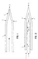
- an exemplary perpendicular spray nozzle is shown in Figure 1.
- An exemplary perpendicular effervescent nozzle is shown in Figure 2.
- the catalyst and optional diluent are carried down the central axis of the tube 1 with an optional atomization gas.
- Some small droplets are suspended in this gas flow and exit the nozzle at the tapered end 2 through the orifices 3 , at least one of which is at least 10° to 20°, preferably 20° to 60°, and most preferably 60 to 90°, off from the central axis of the tube 1 .
- Most of the liquid passes down the tube 1 as a film on the wall or in a liquid slug. These slugs or films are atomized to a fine spray as the carrier gas is forced through the orifices 3 .
- the nozzle can be designed with one or more orifices.
- the orifices should be drilled on the tapered section or on the cylindrical section, and optionally, additional orifices may be drilled at the tip.
- Hole diameter can be designed for a given range of catalyst liquid. Best results have been obtained with the gas to liquid mass flow ratio between about 0.5:1 to about 3:1, preferably between about 0.75:1 to about 1.5:1.
- the diameters are designed so that the gas superficial exit velocity is between about 4 and about 75 m/s, preferably between 9 and 55 m/s, and most preferably between 14 and 28 m/s.
- the actual individual orifice size is not critical, rather total surface area of the orifices is the determining factor.
- a hole at the end of the nozzle tip is optional. Its purpose is to allow a stream of gas to flow out at the tip, thus preventing a stagnant zone at the tip.
- nozzle geometry could be used.
- slots perpendicular to the axis of the tube of about 1 mm x 3 mm may be used instead of holes for the orifices. Slots can be cut along the axis of the cylindrical section near the tip or on the tapered section. Slots could be cut perpendicularly to the tube at those locations. Or, a slot could be made which runs across the end of the tip.
- the tube diameter could range from about 1/8-inch (3.175 mm) to 1/2-inch (12.7 mm).
- the orifice can be between about 0.25 mm to 6mm, preferably between about 1.5 mm and 3 mm.
- the perpendicular spray nozzle is machined from 1/4"(6.35 mm) OD stainless steel rodstock.
- the tip is tapered to a 1.6 mm tip over the last 1.2 cm of the nozzle.
- a 1.27 mm hole is drilled at the tip of the nozzle, and two 1.98 mm holes are drilled at the sides of the tapered section, about 6.4 cm back from the tip. These larger holes are located opposite each other.
- the tips are welded to a 3 m section of standard 1/4-inch (6.4 mm) stainless steel tubing which is used to support the tip and deliver the catalyst solution and carrier gas.
- the tip is located within a jet of tip-cleaning gas of 450 to 1400 kg/hr of heated monomer, which is in turn is located within a jet of cycle gas of 4,000 to 30,000 kg/hr
- FIG. 2 A preferred embodiment of a perpendicular effervescent nozzle is depicted in Figure 2.
- the tip 3 of the outer tube is tapered to a point, with orifices 4 , being present along the tapered tip 3 .
- the orifices 4 are essentially perpendicular to the axis of the nozzle.
- the inner tube is sealed shut at one end 5 , but has holes 6 along its length near the tip. It is noted, though, that the end of the smaller inside tube 5 may be completely open in certain instances.
- the gas of the nozzle be fed into the inner tube 2 and the liquid catalyst in the outer tube 1 , both being fed in the same direction, flowing towards the orifices 4 .
- the gas forms bubbles in the liquid as it exits through the holes 6 and forces the liquid to the outer walls of the tube 1 .
- the gas is assisting in spreading out the liquid.
- Polymers Illustrative of the polymers which can be produced in accordance with the invention are the following: ethylene homopolymers and ethylene copolymers employing one or more C 3 -C 12 alpha olefins; propylene homopolymers and propylene copolymers employing one or more C 4 -C 12 alpha olefins; polyisoprene; polystyrene; polybutadiene; polymers of butadiene copolymerized with styrene; polymers of butadiene copolymerized with acrylonitrile; polymers of isobutylene copolymerized with isoprene; ethylene propylene rubbers and ethylene propylene diene rubbers; polychloroprene, and the like.
- polyethylene of bulk density between 240 to 416 kg/m 3 is made.
- the present invention is not limited to any specific type of gas phase polymerization reaction and can be carried out in a stirred or fluidized bed reactor.
- the invention can be carried out in a single reactor or multiple reactors (two or more reactors in series).
- "condensed mode” including the so-called “induced condensed mode”
- "liquid monomer” operation of a gas phase polymerization can be employed.
- a conventional fluidized bed process for producing resins is practiced by passing a gaseous stream containing one or more monomers continuously through a fluidized bed reactor under reactive conditions in the presence of a polymerization catalyst. Product is withdrawn from the reactor. A gaseous stream of unreacted monomer is withdrawn from the reactor continuously and recycled into the reactor along with make-up monomer added to the recycle stream.
- Condensed mode polymerizations are disclosed in U.S. Patent Nos. 4,543,399; 4,588,790; 5,352,749; and 5,462,999. Condensing mode processes are employed to achieve higher cooling capacities and, hence, higher reactor productivity.
- a recycle stream, or a portion thereof can be cooled to a temperature below the dew point in a fluidized bed polymerization process, resulting in condensing all or a portion of the recycle stream.
- the recycle stream is returned to the reactor.
- the dew point of the recycle stream can be increased by increasing the operating pressure of the reaction/recycle system and/or increasing the percentage of condensable fluids and decreasing the percentage of non-condensable gases in the recycle stream.
- the condensable fluid may be inert to the catalyst, reactants and the polymer product produced; it may also include monomers and comonomers.
- the condensing fluid can be introduced into the reaction/recycle system at any point in the system.
- Condensable fluids include saturated or unsaturated hydrocarbons.
- condensable fluids of the polymerization process itself other condensable fluids, inert to the polymerization can be introduce to "induce" condensing mode operation.
- suitable condensable fluids may be selected from liquid saturated hydrocarbons containing 2 to 8 carbon atoms (e.g., propane, n-butane, isobutane, n-pentane, isopentane, neopentane, n-hexane, isohexane, and other saturated C 6 hydrocarbons, n-heptane, n-octane and other saturated C 7 and C 8 hydrocarbons, and mixtures thereof).
- liquid saturated hydrocarbons containing 2 to 8 carbon atoms e.g., propane, n-butane, isobutane, n-pentane, isopentane, neopentane, n-hexane, isohexane, and other saturated C 6 hydrocarbons, n-heptane, n-octane and other saturated C 7 and C 8 hydrocarbons, and mixtures thereof).
- Condensable fluids may also include polymerizable condensable comonomers such as olefins, alpha-olefins, diolefins, diolefins containing at least one alpha olefin, and mixtures thereof. In condensing mode, it desirable that the liquid entering the fluidized bed be dispersed and vaporized quickly.
- Liquid monomer polymerization mode is disclosed, in U.S. Patent No. 5,453,471, U.S. Serial No. 510,375, PCT 95/09826 (US) and PCT 95/09827 (US).
- liquid monomer present in the bed is adsorbed on or absorbed in solid particulate matter present in the bed, such as polymer being produced or fluidization aids (e.g., carbon black) present in the bed, so long as there is no substantial amount of free liquid monomer present more than a short distance above the point of entry into the polymerization zone.
- Liquid mode makes it possible to produce polymers in a gas phase reactor using monomers having condensation temperatures much higher than the temperatures at which conventional polyolefins are produced.
- liquid monomer process are conducted in a stirred bed or gas fluidized bed reaction vessel having a polymerization zone containing a bed of growing polymer particles.
- the process comprises continuously introducing a stream of one or more monomers and optionally one or more inert gases or liquids into the polymerization zone; continuously or intermittently introducing a polymerization catalyst into the polymerization zone; continuously or intermittently withdrawing polymer product from the polymerization zone; and continuously withdrawing unreacted gases from the zone; compressing and cooling the gases while maintaining the temperature within the zone below the dew point of at least one monomer present in the zone.
- the temperature within the zone and the velocity of gases passing through the zone are such that essentially no liquid is present in the polymerization zone that is not adsorbed on or absorbed in solid particulate matter.
- the liquid catalyst in a carrier gas e.g., nitrogen, argon, alkane, or mixtures thereof
- a carrier gas e.g., nitrogen, argon, alkane, or mixtures thereof
- the first or particle-deflecting gas can be selected from the group consisting of recycle gas, monomer gas, chain transfer gas (e.g., hydrogen), inert gas or mixtures thereof.
- the particle-deflecting gas is all or a portion of recycle gas and the tip-cleaning gas is all or a portion of a monomer (e.g., ethylene or propylene) employed in the process.
- the catalyst used for Examples 1 through 5 was a Zr-based metallocene as a 2 wt % solution in n-hexane.
- the solution was used as made for Examples 1 to 3, but was diluted with 1-hexene for Examples 4 and 5 to 1.33 wt-% catalyst with 32.9% 1-hexene and 65.8% hexane.
- Catalyst was mixed in line with MMAO 3A (modified methyl alumoxane) as received from Akzo Nobel at 7.1 wt % Al. Additional dilution was performed by adding isopentane to the mixture before introducing it to the reactor. Catalyst and MMAO feedrates were adjusted to provide a final Al:Zr molar ratio between 330 and 340.
- MMAO 3A modified methyl alumoxane
- the reactor was 2.4 m in diameter and was operated with a bed height of 11.6 m and a superficial gas velocity of approximately 0.6 m/s. Total reactor pressure was 1960 kPa.
- ATMER-163 an antistatic agent marketed by ICI, was added as necessary to the reactor to control the buildup of electrostatic charge.
- the catalyst atomization devices used in all examples were located at the end of a 1/4" (0.635 cm) OD stainless steel tube, and they could be removed from the reactor during operation. This tube passes through a 3/4-inch (1.9 cm) schedule-40 pipe. A stream of 1000 to 1180 kg/hr of ethylene monomer at a temperature between 85 and 95°C was fed through the annular space between the 1 ⁇ 4-inch tube and the 3/4-inch pipe. This monomer stream is referred to as a nozzle cleaning gas.
- the 3/4-inch pipe was located in the center of a six-inch pipe (15.2 cm), through which was fed between 22,700 and 29,500 kg/hr of cycle gas, known as particle deflecting gas.
- the six-inch pipe extended 53 cm into the reactor, the 3/4-inch pipe extended 61 cm into the reactor, and the spray nozzle extended 66 cm into the reactor, at a location 2.4 m above the distributor plate.
- a Ziegler-Natta seed bed was charged to the reactor and it was dried to 45 ppm water. It was pressurized to 790 kPa of nitrogen and then 36 kg/hr of 10% TEAL (triethyl aluminum) in isopentane were fed to the reactor over two hours and allowed to circulate for 1 hour.
- the reactor was filled with 1650 kPa of ethylene and with a hexene:ethylene molar ratio of 0.033, and the temperature of the fluidized bed was adjusted to 76 °C.
- Catalyst and MMAO were contacted with a static mixer near the injection point at the reactor so that their contact time before dilution with isopentane was approximately 30 seconds.
- Catalyst and cocatalyst solution were fed to the reactor through an injection tube of 0.30-cm inside tip diameter with a stream of 54.5 kg/hr of nitrogen atomization gas.
- the perpendicular spray nozzle as described above as exemplary of a standard pneumatic nozzle was used for examples 2 through 5, in combination with the high flow of recycle gas past the spray nozzle. During those examples only a minimal amount of flaky or hollow particles were formed. The average particle sizes and bulk densities were good, and allowed continuous commercial operation for 10 days.
- a seed bed was charged to the reactor and it was dried to 9 ppm water. It was pressurized to 790 kPa of nitrogen and then 22.7 kg/hr of 10 wt % TEAL in isopentane were fed to the reactor and allowed to circulate for 1 hour.
- the conditions listed in Table 2 below were established in the reactor.
- Catalyst was fed through a perpendicular spray nozzle, located within the stream of 22,700 kg/hr of cycle gas, as described above.
- Catalyst and MMAO were mixed for 15 to 30 seconds.
- the reactor was started with a nitrogen carrier rate of 27.2 kg/hr. This caused the APS of the resin to drop rapidly from 0.66 to 0.356 cm, which was not acceptable for good operation.
- the nitrogen carrier rate was then decreased to 14.3 lbs/hr and the APS increased to 0.533 cm, where it remained stable, and desirable. This shows that by proper control of the nitrogen carrier rate, the APS can be controlled. In other cases, if the APS is too large, the nitrogen carrier rate can be increased to lower the APS back to an acceptable range.
- the APS can also be controlled by adjusting the amount of isopentane diluent added to the catalyst and cocatalyst mixture.
- the reactor was operating with the perpendicular spray nozzle and with the 1.33 wt % catalyst in the mixed hexane/hexene solvent, which was mixed with the MMAO for 19 minutes before being diluted with isopentane and fed to the reactor.
- Several hundred pounds per hour of isopentane were additionally fed to the reactor at a separate location to induce condensing mode operation.
- the amount of isopentane in the cycle gas was thereby increased to about 5 mole percent.
- the reactor was operated with the conditions listed in Example 4, and the APS was stable at 0.483 mm.
- Example 1 The isopentane catalyst diluent feedrate then was decreased for Example 5, as shown in Table 2, and the APS increased to 0.610 mm, demonstrating that the APS can be controlled while in condensing mode, and that it can be controlled with the amount of isopentane diluent added to the catalyst mixture. It was demonstrated throughout the course of the 10 day run with the perpendicular spray nozzle that the APS could be kept in a narrow range by adjusting the nitrogen and isopentane carrier rates independently, or in concert.
- the catalyst was fed without the aid of the 22,700 kg/hr flow of cycle gas around the nozzle as in the previous examples.
- a heated ethylene flow of 1000 kg/hr was directed through a pipe around the nozzle (the nozzle cleaning gas).
- the pipe OD was 4.9 cm and the ID was 2.15 cm. It extended 58 cm into the reactor at a height of 2.4 m above the distributor plate.
- the catalyst atomization device was inserted 64 cm into the reactor.
- the reactor was charged with a seed bed of granular ethylene prepared from a Ziegler-Natta catalyst, and was heated and purged with pure nitrogen until the residual water level dropped to 20 ppm. While the reactor was pressurized with nitrogen, a stream of 36 kg/hr of 10 wt % TEAL was added to the recycle line for two hours. The TEAL was circulated through the reactor for an hour and then the reactor was pressurized further with monomer and comonomer, as shown below for Example 6. The catalyst and MMAO were mixed for approximately 10 to 30 seconds before being diluted with isopentane and fed to the reactor.
- the perpendicular spray nozzle was positioned in the jet of ethylene described above.
- the nitrogen carrier rate was 27.2 kg/hr and the isopentane diluent was set at 3.6 kg/hr.
- the reactor was operated in this configuration for 16 hours and the particle size was stable, with a slight drift upward from 0.635 to 0.686 mm.
Claims (19)
- Procédé comprenant la fourniture d'une quantité efficace sur le plan catalytique d'un catalyseur liquide à un réacteur de polymérisation en phase gazeuse avec une buse de pulvérisation perpendiculaire, dans lequel au moins un trou de sortie dans la buse de pulvérisation perpendiculaire est dévié de plus de 45° par rapport à la direction d'écoulement du liquide dans la buse, et dans lequel le catalyseur liquide est amené dans un réacteur de polymérisation en phase gazeuse à l'aide d'un gaz porteur avec un rapport pondéral du gaz au liquide dans le courant d'alimentation en catalyseur d'environ 0,5/1 à environ 3,0/1.
- Procédé selon la revendication 1, dans lequel la buse perpendiculaire a un courant d'alimentation en gaz et un courant d'alimentation en catalyseur liquide.
- Procédé selon la revendication 2, dans lequel les débits des courants de liquide et de gaz sont liés de façon opérationnelle aux conditions du réacteur de polymérisation.
- Procédé selon la revendication 2, dans lequel le courant d'alimentation en catalyseur liquide contient en outre un liquide autre qu'un catalyseur.
- Procédé selon la revendication 2, dans lequel le gaz est sélectionné parmi le groupe composé de : N2, Ar, He, CH4, C2H6, C3H8, CO2 ou H2.
- Procédé selon la revendication 1, dans lequel un gaz déviant les particules permet au catalyseur de pénétrer dans le réacteur dans une zone pauvre en particules.
- Procédé selon la revendication 3, dans lequel le catalyseur liquide est amené à travers de multiples buses perpendiculaires, chaque buse étant réglée de manière à fournir des tailles de gouttes de catalyseur différentes.
- Procédé selon la revendication 2, dans lequel le réacteur de polymérisation comporte une ligne de recyclage et fonctionne en mode de condensation.
- Procédé selon la revendication 2, dans lequel le catalyseur liquide est une suspension épaisse de catalyseur supporté, une suspension épaisse de catalyseur pré-polymérisé, une suspension de catalyseur supporté ou une suspension de catalyseur pré-polymérisé.
- Procédé selon la revendication 1, comprenant en outre la fourniture d'un co-catalyseur au réacteur autrement que par la buse perpendiculaire.
- Procédé pour fournir un catalyseur liquide à un réacteur de polymérisation en phase gazeuse à l'aide d'un gaz porteur avec un rapport pondéral du gaz au liquide dans le courant d'alimentation en catalyseur d'environ 0,5/1 à environ 3,0/1, et un débit de gaz dans la buse compris entre environ 5 et 200 kg/h ; dans lequel le catalyseur est amené dans une buse perpendiculaire, dans lequel au moins un trou de sortie de la buse de pulvérisation est dévié de plus de 45° par rapport à la direction d'écoulement du liquide dans la buse.
- Procédé selon la revendication 11, dans lequel les débits des courants de liquide et de gaz sont liés de façon opérationnelle aux conditions du réacteur de polymérisation.
- Procédé selon la revendication 12, dans lequel la buse présente un orifice qui peut être automatiquement dilaté.
- Procédé selon la revendication 12, dans lequel un gaz déviant les particules permet au catalyseur de pénétrer dans le réacteur dans une zone pauvre en particules.
- Procédé selon la revendication 12, dans lequel le catalyseur liquide est amené à travers de multiples buses perpendiculaires, chaque buse étant réglée de manière à fournir des tailles de gouttes de catalyseur différentes.
- Procédé selon la revendication 12, dans lequel le réacteur de polymérisation comporte une ligne de recyclage et fonctionne en mode de condensation.
- Procédé selon la revendication 12, dans lequel le catalyseur liquide est une suspension épaisse de catalyseur supporté, une suspension épaisse de catalyseur pré-polymérisé, une suspension de catalyseur supporté ou une suspension de catalyseur pré-polymérisé.
- Procédé selon la revendication 12, comprenant en outre la fourniture d'un co-catalyseur au réacteur autrement que par la buse perpendiculaire.
- Procédé selon la revendication 12, dans lequel le gaz est sélectionné parmi le groupe composé de : N2, Ar, He, CH4, C2H6, C3H8, CO2 ou H2.
Applications Claiming Priority (3)
| Application Number | Priority Date | Filing Date | Title |
|---|---|---|---|
| US802230 | 1997-02-19 | ||
| US08/802,230 US6075101A (en) | 1997-02-19 | 1997-02-19 | Control of solution catalyst droplet size with a perpendicular spray nozzle |
| PCT/US1998/003139 WO1998037102A1 (fr) | 1997-02-19 | 1998-02-18 | Reglage ameliore de la taille des gouttelettes d'un catalyseur en solution par une buse de pulverisation perpendiculaire |
Publications (2)
| Publication Number | Publication Date |
|---|---|
| EP0961785A1 EP0961785A1 (fr) | 1999-12-08 |
| EP0961785B1 true EP0961785B1 (fr) | 2003-03-12 |
Family
ID=25183156
Family Applications (1)
| Application Number | Title | Priority Date | Filing Date |
|---|---|---|---|
| EP98906546A Expired - Lifetime EP0961785B1 (fr) | 1997-02-19 | 1998-02-18 | Reglage ameliore de la taille des gouttelettes d'un catalyseur en solution par une buse de pulverisation perpendiculaire |
Country Status (13)
| Country | Link |
|---|---|
| US (1) | US6075101A (fr) |
| EP (1) | EP0961785B1 (fr) |
| JP (1) | JP2000512335A (fr) |
| AR (1) | AR011827A1 (fr) |
| AT (1) | ATE234327T1 (fr) |
| AU (1) | AU738931B2 (fr) |
| BR (1) | BR9806797A (fr) |
| CA (1) | CA2281561C (fr) |
| DE (1) | DE69812072T2 (fr) |
| ES (1) | ES2189135T3 (fr) |
| ID (1) | ID20477A (fr) |
| WO (1) | WO1998037102A1 (fr) |
| ZA (1) | ZA981298B (fr) |
Families Citing this family (25)
| Publication number | Priority date | Publication date | Assignee | Title |
|---|---|---|---|---|
| US6245868B1 (en) * | 1998-05-29 | 2001-06-12 | Univation Technologies | Catalyst delivery method, a catalyst feeder and their use in a polymerization process |
| US6260385B1 (en) * | 1998-08-07 | 2001-07-17 | Corning Incorporated | Method and burner for forming silica-containing soot |
| CN1101409C (zh) * | 1999-08-30 | 2003-02-12 | 中国石油化工集团公司 | 冷凝模式下操作的流化床聚合反应器中引入冷凝剂的改进 |
| US6363746B1 (en) * | 2000-03-15 | 2002-04-02 | Corning Incorporated | Method and apparatus for making multi-component glass soot |
| FR2809031B1 (fr) * | 2000-05-17 | 2003-06-06 | Federation Vendee Rech | Diffuseur pneumatique pour la formation de fines gouttelettes d'un liquide par collision avec un flux gazeux |
| US6391986B1 (en) * | 2000-12-05 | 2002-05-21 | Union Carbide Chemicals & Plastics Technology Corporation | Control of solution catalyst droplets |
| WO2002077045A2 (fr) * | 2001-03-27 | 2002-10-03 | Union Carbide Chemicals & Plastics Technology Corporation | Processus en phase gazeuse pour polymeres avec adjonction catalytique de complexe metallique de groupe 4 |
| US7680688B2 (en) * | 2002-05-28 | 2010-03-16 | American Express Travel Related Services Company, Inc. | System and method for exchanging loyalty points for acquisitions |
| AU2004247640B2 (en) * | 2003-05-30 | 2009-12-24 | Univation Technologies, Llc | Gas phase polymerization and method of controlling same |
| JP2006043545A (ja) * | 2004-08-02 | 2006-02-16 | Ricoh Co Ltd | 有機微結晶作製装置及び有機微結晶作製方法並びに有機微結晶 |
| JP5198872B2 (ja) | 2004-12-17 | 2013-05-15 | ダウ グローバル テクノロジーズ エルエルシー | レオロジー改変相対的高溶融強度ポリエチレン組成物並びにパイプ、フィルム、シート、およびブロー成型品の製造方法 |
| US7989562B2 (en) * | 2006-10-03 | 2011-08-02 | Univation Technologies, Llc | Method for preventing catalyst agglomeration based on production rate changes |
| TWI432456B (zh) | 2006-10-03 | 2014-04-01 | Univation Tech Llc | 用於觸媒注射之泡騰噴嘴 |
| DE102007025317A1 (de) * | 2007-05-31 | 2008-12-04 | Süd-Chemie AG | Vorrichtung zur Herstellung eines als Schalenkatalysator ausgebildeten geträgerten Edelmetallkatalysators |
| DE102007025442B4 (de) | 2007-05-31 | 2023-03-02 | Clariant International Ltd. | Verwendung einer Vorrichtung zur Herstellung eines Schalenkatalysators und Schalenkatalysator |
| DE102007025223A1 (de) | 2007-05-31 | 2008-12-04 | Süd-Chemie AG | Zirkoniumoxid-dotierter VAM-Schalenkatalysator, Verfahren zu dessen Herstellung sowie dessen Verwendung |
| CN101977676B (zh) * | 2008-01-24 | 2014-10-15 | 陶氏环球技术有限责任公司 | 气相聚合的方法 |
| TWI433855B (zh) * | 2008-06-04 | 2014-04-11 | Univation Tech Llc | 漿液觸媒流分流器及其使用方法 |
| CA2738661C (fr) * | 2008-10-01 | 2014-07-15 | Fluor Technologies Corporation | Configurations et procedes de buses de pulverisation assistee au gaz |
| DE102008059341A1 (de) | 2008-11-30 | 2010-06-10 | Süd-Chemie AG | Katalysatorträger, Verfahren zu seiner Herstellung sowie Verwendung |
| CN103124593B (zh) * | 2010-09-27 | 2016-01-06 | 国际壳牌研究有限公司 | 进料管嘴装置 |
| US9234060B2 (en) | 2011-11-08 | 2016-01-12 | Univation Technologies, Llc | Methods of preparing a catalyst system |
| EP4063402A1 (fr) | 2015-04-17 | 2022-09-28 | Univation Technologies, LLC | Procédés et systèmes permettant la polymérisation d'oléfines |
| US11186654B2 (en) | 2016-12-20 | 2021-11-30 | Exxonmobil Chemical Patents Inc. | Methods for controlling start up conditions in polymerization processes |
| CN110114133B (zh) | 2017-01-20 | 2021-08-27 | 巴塞尔聚烯烃意大利有限公司 | 将流体进料至气相聚合反应器中的方法 |
Family Cites Families (16)
| Publication number | Priority date | Publication date | Assignee | Title |
|---|---|---|---|---|
| FR2215802A5 (en) * | 1972-12-28 | 1974-08-23 | Solvay | Fluidised bed polymn using cooling liq. injection - with non return valve on nozzles to prevent back flow of powder clogging feed pipes |
| US4163040A (en) * | 1977-11-21 | 1979-07-31 | National Distillers And Chemical Corporation | Catalyst spray nozzle |
| US4222986A (en) * | 1979-01-09 | 1980-09-16 | Exxon Research & Engineering Co. | Autorefrigeration polymerization apparatus |
| US5174889A (en) * | 1983-10-06 | 1992-12-29 | Phillips Petroleum Company | Atomizing feed for cracking unit |
| DD222504A1 (de) * | 1983-11-14 | 1985-05-22 | Dampferzeugerbau Veb K | Einrichtung zur stoffaufgabe in wirbelschichtanlagen |
| US4640463A (en) * | 1984-01-19 | 1987-02-03 | Mobil Oil Corporation | Apparatus for injecting liquid hydrocarbon feed and steam into a catalytic cracking zone |
| JPH0662704B2 (ja) * | 1985-03-11 | 1994-08-17 | 三菱化成株式会社 | オレフインの気相重合方法 |
| US5213768A (en) * | 1987-06-30 | 1993-05-25 | Bp Chemicals Ltd. | Fluidized bed apparatus and process for feeding gas to a fluidized bed apparatus |
| RU1630066C (ru) * | 1988-12-13 | 1995-02-27 | Куйбышевский филиал Всероссийского научно-исследовательского института по переработке нефти | Реактор сополимеризации изобутилена с бутиленами |
| US5269980A (en) * | 1991-08-05 | 1993-12-14 | Northeastern University | Production of polymer particles in powder form using an atomization technique |
| US5317036A (en) * | 1992-10-16 | 1994-05-31 | Union Carbide Chemicals & Plastics Technology Corporation | Gas phase polymerization reactions utilizing soluble unsupported catalysts |
| ZA943399B (en) * | 1993-05-20 | 1995-11-17 | Bp Chem Int Ltd | Polymerisation process |
| GB9500226D0 (en) * | 1995-01-06 | 1995-03-01 | Bp Chem Int Ltd | Nozzle |
| US5744556A (en) * | 1995-09-25 | 1998-04-28 | Union Carbide Chemicals & Plastics Technology Corporation | Gas phase polymerization employing unsupported catalysts |
| GB9524038D0 (en) * | 1995-11-23 | 1996-01-24 | Bp Chem Int Ltd | Nozzle |
| US5693727A (en) * | 1996-06-06 | 1997-12-02 | Union Carbide Chemicals & Plastics Technology Corporation | Method for feeding a liquid catalyst to a fluidized bed polymerization reactor |
-
1997
- 1997-02-19 US US08/802,230 patent/US6075101A/en not_active Expired - Fee Related
-
1998
- 1998-02-12 ID IDP980190A patent/ID20477A/id unknown
- 1998-02-17 ZA ZA981298A patent/ZA981298B/xx unknown
- 1998-02-18 ES ES98906546T patent/ES2189135T3/es not_active Expired - Lifetime
- 1998-02-18 DE DE69812072T patent/DE69812072T2/de not_active Expired - Fee Related
- 1998-02-18 AT AT98906546T patent/ATE234327T1/de not_active IP Right Cessation
- 1998-02-18 AU AU61743/98A patent/AU738931B2/en not_active Ceased
- 1998-02-18 BR BR9806797-4A patent/BR9806797A/pt not_active IP Right Cessation
- 1998-02-18 WO PCT/US1998/003139 patent/WO1998037102A1/fr active IP Right Grant
- 1998-02-18 CA CA002281561A patent/CA2281561C/fr not_active Expired - Fee Related
- 1998-02-18 EP EP98906546A patent/EP0961785B1/fr not_active Expired - Lifetime
- 1998-02-18 AR ARP980100718A patent/AR011827A1/es unknown
- 1998-02-18 JP JP10536837A patent/JP2000512335A/ja active Pending
Also Published As
| Publication number | Publication date |
|---|---|
| JP2000512335A (ja) | 2000-09-19 |
| ATE234327T1 (de) | 2003-03-15 |
| AU6174398A (en) | 1998-09-09 |
| ES2189135T3 (es) | 2003-07-01 |
| DE69812072T2 (de) | 2003-08-21 |
| ZA981298B (en) | 1998-08-28 |
| US6075101A (en) | 2000-06-13 |
| CA2281561C (fr) | 2003-03-11 |
| AR011827A1 (es) | 2000-09-13 |
| CA2281561A1 (fr) | 1998-08-27 |
| AU738931B2 (en) | 2001-09-27 |
| ID20477A (id) | 1998-12-24 |
| BR9806797A (pt) | 2000-05-16 |
| WO1998037102A1 (fr) | 1998-08-27 |
| DE69812072D1 (de) | 2003-04-17 |
| EP0961785A1 (fr) | 1999-12-08 |
Similar Documents
| Publication | Publication Date | Title |
|---|---|---|
| EP0961785B1 (fr) | Reglage ameliore de la taille des gouttelettes d'un catalyseur en solution par une buse de pulverisation perpendiculaire | |
| EP0961784B1 (fr) | Reglage ameliore de la taille des gouttelettes d'un catalyseur en solution par une buse de vaporisation de fluide effervescent | |
| US5948871A (en) | Method for feeding a liquid catalyst to a fluidized bed polymerization reactor | |
| EP1358218B1 (fr) | Controle de gouttelettes catalytiques en solution | |
| AU2002241588A1 (en) | Control of solution catalyst droplets | |
| EP1155051B1 (fr) | Compositions de catalyseurs non supportes dans une concentration donnee et procedes d'utilisation desdites compositions | |
| US6251817B1 (en) | Method of reducing tube plugging using preactivated unsupported catalysts | |
| WO1998037103A1 (fr) | Production de polyolefines dont les particules presentent une dimension commandee | |
| MXPA99007618A (en) | Improved control of solution catalyst droplet size with a perpendicular spray nozzle | |
| WO2000039174A1 (fr) | Catalyseurs sans support preactives et procedes d'utilisation de ceux-ci | |
| MXPA99007611A (en) | Improved control of solution catalyst droplet size with an effervescent spray nozzle |
Legal Events
| Date | Code | Title | Description |
|---|---|---|---|
| PUAI | Public reference made under article 153(3) epc to a published international application that has entered the european phase |
Free format text: ORIGINAL CODE: 0009012 |
|
| 17P | Request for examination filed |
Effective date: 19990706 |
|
| AK | Designated contracting states |
Kind code of ref document: A1 Designated state(s): AT BE DE ES FR GB GR IT NL PT SE |
|
| 17Q | First examination report despatched |
Effective date: 20011122 |
|
| GRAG | Despatch of communication of intention to grant |
Free format text: ORIGINAL CODE: EPIDOS AGRA |
|
| GRAG | Despatch of communication of intention to grant |
Free format text: ORIGINAL CODE: EPIDOS AGRA |
|
| GRAH | Despatch of communication of intention to grant a patent |
Free format text: ORIGINAL CODE: EPIDOS IGRA |
|
| GRAH | Despatch of communication of intention to grant a patent |
Free format text: ORIGINAL CODE: EPIDOS IGRA |
|
| GRAA | (expected) grant |
Free format text: ORIGINAL CODE: 0009210 |
|
| AK | Designated contracting states |
Designated state(s): AT BE DE ES FR GB GR IT NL PT SE |
|
| PG25 | Lapsed in a contracting state [announced via postgrant information from national office to epo] |
Ref country code: GR Free format text: LAPSE BECAUSE OF FAILURE TO SUBMIT A TRANSLATION OF THE DESCRIPTION OR TO PAY THE FEE WITHIN THE PRESCRIBED TIME-LIMIT Effective date: 20030312 Ref country code: AT Free format text: LAPSE BECAUSE OF FAILURE TO SUBMIT A TRANSLATION OF THE DESCRIPTION OR TO PAY THE FEE WITHIN THE PRESCRIBED TIME-LIMIT Effective date: 20030312 |
|
| REG | Reference to a national code |
Ref country code: GB Ref legal event code: FG4D |
|
| REF | Corresponds to: |
Ref document number: 69812072 Country of ref document: DE Date of ref document: 20030417 Kind code of ref document: P |
|
| PG25 | Lapsed in a contracting state [announced via postgrant information from national office to epo] |
Ref country code: PT Free format text: LAPSE BECAUSE OF FAILURE TO SUBMIT A TRANSLATION OF THE DESCRIPTION OR TO PAY THE FEE WITHIN THE PRESCRIBED TIME-LIMIT Effective date: 20030616 |
|
| REG | Reference to a national code |
Ref country code: SE Ref legal event code: TRGR Ref country code: ES Ref legal event code: FG2A Ref document number: 2189135 Country of ref document: ES Kind code of ref document: T3 |
|
| ET | Fr: translation filed | ||
| PLBE | No opposition filed within time limit |
Free format text: ORIGINAL CODE: 0009261 |
|
| STAA | Information on the status of an ep patent application or granted ep patent |
Free format text: STATUS: NO OPPOSITION FILED WITHIN TIME LIMIT |
|
| 26N | No opposition filed |
Effective date: 20031215 |
|
| PGFP | Annual fee paid to national office [announced via postgrant information from national office to epo] |
Ref country code: NL Payment date: 20070204 Year of fee payment: 10 |
|
| PGFP | Annual fee paid to national office [announced via postgrant information from national office to epo] |
Ref country code: SE Payment date: 20070206 Year of fee payment: 10 |
|
| PGFP | Annual fee paid to national office [announced via postgrant information from national office to epo] |
Ref country code: BE Payment date: 20070423 Year of fee payment: 10 |
|
| PGFP | Annual fee paid to national office [announced via postgrant information from national office to epo] |
Ref country code: ES Payment date: 20080123 Year of fee payment: 11 |
|
| PGFP | Annual fee paid to national office [announced via postgrant information from national office to epo] |
Ref country code: IT Payment date: 20071229 Year of fee payment: 11 Ref country code: GB Payment date: 20080108 Year of fee payment: 11 Ref country code: DE Payment date: 20080131 Year of fee payment: 11 |
|
| PGFP | Annual fee paid to national office [announced via postgrant information from national office to epo] |
Ref country code: FR Payment date: 20080107 Year of fee payment: 11 |
|
| BERE | Be: lapsed |
Owner name: *UNION CARBIDE CHEMICALS & PLASTICS TECHNOLOGY COR Effective date: 20080228 |
|
| EUG | Se: european patent has lapsed | ||
| NLV4 | Nl: lapsed or anulled due to non-payment of the annual fee |
Effective date: 20080901 |
|
| PG25 | Lapsed in a contracting state [announced via postgrant information from national office to epo] |
Ref country code: NL Free format text: LAPSE BECAUSE OF NON-PAYMENT OF DUE FEES Effective date: 20080901 |
|
| PG25 | Lapsed in a contracting state [announced via postgrant information from national office to epo] |
Ref country code: SE Free format text: LAPSE BECAUSE OF NON-PAYMENT OF DUE FEES Effective date: 20080219 |
|
| PG25 | Lapsed in a contracting state [announced via postgrant information from national office to epo] |
Ref country code: BE Free format text: LAPSE BECAUSE OF NON-PAYMENT OF DUE FEES Effective date: 20080228 |
|
| GBPC | Gb: european patent ceased through non-payment of renewal fee |
Effective date: 20090218 |
|
| REG | Reference to a national code |
Ref country code: FR Ref legal event code: ST Effective date: 20091030 |
|
| PG25 | Lapsed in a contracting state [announced via postgrant information from national office to epo] |
Ref country code: DE Free format text: LAPSE BECAUSE OF NON-PAYMENT OF DUE FEES Effective date: 20090901 |
|
| REG | Reference to a national code |
Ref country code: ES Ref legal event code: FD2A Effective date: 20090219 |
|
| PG25 | Lapsed in a contracting state [announced via postgrant information from national office to epo] |
Ref country code: GB Free format text: LAPSE BECAUSE OF NON-PAYMENT OF DUE FEES Effective date: 20090218 Ref country code: FR Free format text: LAPSE BECAUSE OF NON-PAYMENT OF DUE FEES Effective date: 20090302 |
|
| PG25 | Lapsed in a contracting state [announced via postgrant information from national office to epo] |
Ref country code: ES Free format text: LAPSE BECAUSE OF NON-PAYMENT OF DUE FEES Effective date: 20090219 |
|
| PG25 | Lapsed in a contracting state [announced via postgrant information from national office to epo] |
Ref country code: IT Free format text: LAPSE BECAUSE OF NON-PAYMENT OF DUE FEES Effective date: 20090218 |