EP0961380A2 - Circuit de protection pour déconnecter un circuit de courant continu - Google Patents
Circuit de protection pour déconnecter un circuit de courant continu Download PDFInfo
- Publication number
- EP0961380A2 EP0961380A2 EP99107487A EP99107487A EP0961380A2 EP 0961380 A2 EP0961380 A2 EP 0961380A2 EP 99107487 A EP99107487 A EP 99107487A EP 99107487 A EP99107487 A EP 99107487A EP 0961380 A2 EP0961380 A2 EP 0961380A2
- Authority
- EP
- European Patent Office
- Prior art keywords
- switch
- fuse
- circuit
- direct current
- circuit arrangement
- Prior art date
- Legal status (The legal status is an assumption and is not a legal conclusion. Google has not performed a legal analysis and makes no representation as to the accuracy of the status listed.)
- Withdrawn
Links
Images
Classifications
-
- B—PERFORMING OPERATIONS; TRANSPORTING
- B60—VEHICLES IN GENERAL
- B60L—PROPULSION OF ELECTRICALLY-PROPELLED VEHICLES; SUPPLYING ELECTRIC POWER FOR AUXILIARY EQUIPMENT OF ELECTRICALLY-PROPELLED VEHICLES; ELECTRODYNAMIC BRAKE SYSTEMS FOR VEHICLES IN GENERAL; MAGNETIC SUSPENSION OR LEVITATION FOR VEHICLES; MONITORING OPERATING VARIABLES OF ELECTRICALLY-PROPELLED VEHICLES; ELECTRIC SAFETY DEVICES FOR ELECTRICALLY-PROPELLED VEHICLES
- B60L3/00—Electric devices on electrically-propelled vehicles for safety purposes; Monitoring operating variables, e.g. speed, deceleration or energy consumption
- B60L3/0023—Detecting, eliminating, remedying or compensating for drive train abnormalities, e.g. failures within the drive train
-
- H—ELECTRICITY
- H02—GENERATION; CONVERSION OR DISTRIBUTION OF ELECTRIC POWER
- H02H—EMERGENCY PROTECTIVE CIRCUIT ARRANGEMENTS
- H02H3/00—Emergency protective circuit arrangements for automatic disconnection directly responsive to an undesired change from normal electric working condition with or without subsequent reconnection ; integrated protection
- H02H3/08—Emergency protective circuit arrangements for automatic disconnection directly responsive to an undesired change from normal electric working condition with or without subsequent reconnection ; integrated protection responsive to excess current
- H02H3/087—Emergency protective circuit arrangements for automatic disconnection directly responsive to an undesired change from normal electric working condition with or without subsequent reconnection ; integrated protection responsive to excess current for DC applications
-
- H—ELECTRICITY
- H01—ELECTRIC ELEMENTS
- H01H—ELECTRIC SWITCHES; RELAYS; SELECTORS; EMERGENCY PROTECTIVE DEVICES
- H01H33/00—High-tension or heavy-current switches with arc-extinguishing or arc-preventing means
- H01H33/02—Details
- H01H33/59—Circuit arrangements not adapted to a particular application of the switch and not otherwise provided for, e.g. for ensuring operation of the switch at a predetermined point in the AC cycle
- H01H33/596—Circuit arrangements not adapted to a particular application of the switch and not otherwise provided for, e.g. for ensuring operation of the switch at a predetermined point in the AC cycle for interrupting DC
-
- H—ELECTRICITY
- H01—ELECTRIC ELEMENTS
- H01H—ELECTRIC SWITCHES; RELAYS; SELECTORS; EMERGENCY PROTECTIVE DEVICES
- H01H9/00—Details of switching devices, not covered by groups H01H1/00 - H01H7/00
- H01H9/10—Adaptation for built-in fuses
- H01H9/106—Adaptation for built-in fuses fuse and switch being connected in parallel
Definitions
- the invention relates to a protective circuit arrangement for disconnection a DC circuit.
- DC circuits used only for protection purposes e.g. to prevent the risk of fire in the case of a defective component, must be switched off, either with a appropriate DC switch or are equipped with a on the entire device - and not just the defective DC circuit - active fuse switched off.
- the disadvantage of the former solution is in the fact that DC switching devices are very complex and expensive, while in the latter variant the availability of the system decreases, whereby fault location is correspondingly difficult.
- a special area of application for such a protective circuit is one Drive multi-axis machine tools by means of individual axis actuators.
- in the Braking is energy in an intermediate circuit capacitor charged so that its tension increases.
- a resistor becomes parallel to the intermediate circuit switched and thereby some of the braking energy is converted into heat.
- Of the Resistance is always switched on when the DC link voltage exceeds a certain value, so that a certain switching frequency results.
- the chopper is connected via a power semiconductor, e.g. about an IGBT.
- IGBT power semiconductor
- the DC voltage circuit is switched off according to the characterizing features of claim 1, by a first AC switch with fuse connected in parallel as Release agent is used.
- AC switches especially three-phase contactors, which are essential are more compact and cheaper than DC switches, have in the Usually only a very limited switching capacity for direct current.
- the cause the reason for this is that when the switch contact opens arcing does not occur as with alternating current in the natural Zero crossing of the current goes out. So that no arc arises, must for the period of time in which the switching contacts move from the closed in move the open switch position, a bypass to the protective contact be created, with a backup after fully opening the Protective contacts interrupt the current automatically.
- switched three-phase current protection can a direct current circuit in the event of an accident switch off.
- the nominal current of the fuse must be the smallest in the circuit flowing direct current to ensure that the fuse blows even with the smallest currents.
- a fuse can be connected to the nominal current of the Fuse designed second AC switch may be provided.
- A such as a separator without breaking capacity AC switch disconnects the load when switched off Main contactor from the circuit.
- the second AC switch is from the first AC switch (main contactor) only opens when it is open and the fuse has blown.
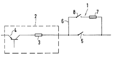
- the figure shows a protective circuit arrangement 1 in connection with a Brake chopper assembly 2 arranged in a DC circuit is.
- the brake chopper assembly 2 consists essentially of one Braking resistor 3 and one of them switching cyclically Power semiconductor 4. When the power semiconductor 4 is destroyed in one larger plant, the plant can continue to be operated. However, must the braking resistor 3 assigned to the defective power semiconductor 4 be switched off immediately, otherwise it could cause a fire can.
- Protective circuit arrangement 1 is provided for this.
- the Protective circuit arrangement 1 has a first AC switch 5, e.g. a GS contactor, which has one or more parallel contacts has the serial to the brake chopper assembly 2 are arranged.
- the first AC switch 5 is bypass-like from a current path 6 a fuse 7 and a second AC switch 8 bridges.
- the DC circuit must be opened, i.e. the first AC switch 5 is from the closed to the open Switch position moved.
- the switch current commutates to the parallel one Current path 6 with the fuse 7, so that no voltage on itself opening contact of the first AC switch 5 is induced and ultimately preventing the formation of an arc.
- the Fuse characteristic is chosen such that the melting time of the Fuse 7 is greater than the time that the first AC switch 5 needed for full opening. After the melting time is over Current path 6 separated. To be on the safe side, this will be Circuit breakage by the second AC switch 8 supported.
- This second AC switch 8 the rated current the fuse 7 is designed, the first AC switch 5 then operated when the AC switch 5 is fully opened and the fuse 7 has blown.
- the invention is not limited to the above Embodiment. Rather, a number of variants are possible which, even if the execution is fundamentally different, from the Make use of features of the invention.
Landscapes
- Engineering & Computer Science (AREA)
- Life Sciences & Earth Sciences (AREA)
- Sustainable Development (AREA)
- Sustainable Energy (AREA)
- Power Engineering (AREA)
- Transportation (AREA)
- Mechanical Engineering (AREA)
- Fuses (AREA)
- Emergency Protection Circuit Devices (AREA)
Applications Claiming Priority (2)
| Application Number | Priority Date | Filing Date | Title |
|---|---|---|---|
| DE19824269 | 1998-05-29 | ||
| DE1998124269 DE19824269A1 (de) | 1998-05-29 | 1998-05-29 | Schutzschaltungsanordnung zum Auftrennen eines Gleichstromkreises |
Publications (2)
| Publication Number | Publication Date |
|---|---|
| EP0961380A2 true EP0961380A2 (fr) | 1999-12-01 |
| EP0961380A3 EP0961380A3 (fr) | 2000-10-18 |
Family
ID=7869431
Family Applications (1)
| Application Number | Title | Priority Date | Filing Date |
|---|---|---|---|
| EP99107487A Withdrawn EP0961380A3 (fr) | 1998-05-29 | 1999-04-29 | Circuit de protection pour déconnecter un circuit de courant continu |
Country Status (2)
| Country | Link |
|---|---|
| EP (1) | EP0961380A3 (fr) |
| DE (1) | DE19824269A1 (fr) |
Cited By (2)
| Publication number | Priority date | Publication date | Assignee | Title |
|---|---|---|---|---|
| EP1300919A1 (fr) * | 2001-10-08 | 2003-04-09 | LEONI Bordnetz-Systeme GmbH & Co KG | Réseau électrique et procédé pour la protéction du réseau contre les arcs électriques |
| WO2019115714A1 (fr) * | 2017-12-15 | 2019-06-20 | Bayerische Motoren Werke Aktiengesellschaft | Dispositif de séparation pour un réseau de bord à haute tension d'un véhicule automobile, réseau de bord à haute tension et véhicule automobile |
Families Citing this family (1)
| Publication number | Priority date | Publication date | Assignee | Title |
|---|---|---|---|---|
| DE102013012578B4 (de) * | 2013-07-30 | 2023-10-05 | Lisa Dräxlmaier GmbH | Vorrichtung zum Absichern einer elektrischen Leitung sowie Verfahren zum Betreiben einer auf einer elektrischen Leitung angeordneten Vorrichtung |
Family Cites Families (5)
| Publication number | Priority date | Publication date | Assignee | Title |
|---|---|---|---|---|
| US3544843A (en) * | 1967-12-19 | 1970-12-01 | Westinghouse Electric Corp | High-voltage direct current circuit interrupter |
| DE2906556C2 (de) * | 1979-02-17 | 1984-04-26 | Licentia Patent-Verwaltungs-Gmbh, 6000 Frankfurt | Überstromschutzanordnung bei Fehlkummutierungen eines Thyristor-Wechselrichters eines Zwischenkreuzumrichters |
| JPH03135385A (ja) * | 1989-10-18 | 1991-06-10 | Fuji Electric Co Ltd | 制動抵抗の過熱保護方法 |
| ATE101761T1 (de) * | 1990-04-06 | 1994-03-15 | Siemens Ag | Schutz- und ueberwachungseinrichtung fuer eine pulswiderstandsanordnung eines spannungszwischenkreisumrichters. |
| AT397003B (de) * | 1992-01-16 | 1994-01-25 | Holly Rudolf | Einrichtung zum abschalten eines hochspannungsstromkreises |
-
1998
- 1998-05-29 DE DE1998124269 patent/DE19824269A1/de not_active Ceased
-
1999
- 1999-04-29 EP EP99107487A patent/EP0961380A3/fr not_active Withdrawn
Cited By (5)
| Publication number | Priority date | Publication date | Assignee | Title |
|---|---|---|---|---|
| EP1300919A1 (fr) * | 2001-10-08 | 2003-04-09 | LEONI Bordnetz-Systeme GmbH & Co KG | Réseau électrique et procédé pour la protéction du réseau contre les arcs électriques |
| US6912110B2 (en) | 2001-10-08 | 2005-06-28 | Leoni Bordnetz-Systeme | Cable network and method for protecting the cable network against a serial arc |
| WO2019115714A1 (fr) * | 2017-12-15 | 2019-06-20 | Bayerische Motoren Werke Aktiengesellschaft | Dispositif de séparation pour un réseau de bord à haute tension d'un véhicule automobile, réseau de bord à haute tension et véhicule automobile |
| CN111201687A (zh) * | 2017-12-15 | 2020-05-26 | 宝马股份公司 | 用于机动车辆的高压车载电网的断开装置、高压车载电网以及机动车辆 |
| US11440412B2 (en) | 2017-12-15 | 2022-09-13 | Bayerische Motoren Werke Aktiengesellschaft | Disconnection device for a high-voltage electrical system of a motor vehicle, high-voltage electrical system, and motor vehicle |
Also Published As
| Publication number | Publication date |
|---|---|
| DE19824269A1 (de) | 1999-12-02 |
| EP0961380A3 (fr) | 2000-10-18 |
Similar Documents
| Publication | Publication Date | Title |
|---|---|---|
| EP3987559B1 (fr) | Dispositif de commutateur de protection, système de protection à interruption et procédé correspondant | |
| EP2048679B1 (fr) | Agencement de sectionneur à coupure en charge | |
| DE2710159C2 (fr) | ||
| EP3091550A1 (fr) | Dispositif de commutation hybride | |
| DE102015226475A1 (de) | Schalteinrichtung | |
| DE2612922C2 (de) | Lastumschalter für Stufentransformatoren mit je einem in den beiden Lastzweigen angeordneten Paar von antiparallel geschalteten Thyristoren | |
| DE19711622C1 (de) | Verfahren und Vorrichtung zum Betreiben einer in einen Stromkreis geschalteten, elektrischen Last | |
| EP0453776B1 (fr) | Mécanisme de couplage avec disjoncteur ou sectionneur de charge et fusible | |
| EP0961380A2 (fr) | Circuit de protection pour déconnecter un circuit de courant continu | |
| DE4005532A1 (de) | Generator-leistungsschalter | |
| EP0126882A2 (fr) | Installation de commutation pour la distribution d'énergie électrique et procédé pour commander l'installation | |
| DE2702181C3 (de) | Kurzschluß-Schutzschaltung für über Halbleiterschalter ein- oder ausschaltbare Geräte, insbesondere für Lichtsteuergeräte | |
| EP3771053A1 (fr) | Dispositif de surveillance d'arc électrique parasite, en particulier pour les installation de commutation basse tension | |
| DE102019213390A1 (de) | Verfahren zur Ansteuerung eines elektrischen Schalters | |
| LU505555B1 (de) | Trennschalter | |
| DE19508763C2 (de) | Anordnung zur Überwachung eines Leistungsschaltgerätes | |
| EP0613427B1 (fr) | Circuits pour sous-stations de redressement | |
| DE3926990C2 (de) | Netzumschalteinrichtung | |
| DE4023238A1 (de) | Schaltungsanordnung mit einem transformator | |
| DE745234C (de) | Hochspannungsschaltanlage | |
| DE19528020A1 (de) | Sich selbsttätig überwachender Fehlerstromschutzschalter | |
| EP0844632A2 (fr) | Agencement de contact pour disjoncteur à courant de défaut | |
| DE1640053A1 (de) | Sicherungsueberwachung fuer Sicherungstrennschalter | |
| DD144844A1 (de) | Verfahren und vorrichtung zur abschaltung von kurzschlussstroemen | |
| DE2925109A1 (de) | Verfahren zur abschaltung von kurzschlusstroemen in elektrischen hochspannungsanlagen und einrichtung zu dessen durchfuehrung |
Legal Events
| Date | Code | Title | Description |
|---|---|---|---|
| PUAI | Public reference made under article 153(3) epc to a published international application that has entered the european phase |
Free format text: ORIGINAL CODE: 0009012 |
|
| AK | Designated contracting states |
Kind code of ref document: A2 Designated state(s): CH DE FR GB LI |
|
| AX | Request for extension of the european patent |
Free format text: AL;LT;LV;MK;RO;SI |
|
| PUAL | Search report despatched |
Free format text: ORIGINAL CODE: 0009013 |
|
| AK | Designated contracting states |
Kind code of ref document: A3 Designated state(s): AT BE CH CY DE DK ES FI FR GB GR IE IT LI LU MC NL PT SE |
|
| AX | Request for extension of the european patent |
Free format text: AL;LT;LV;MK;RO;SI |
|
| RIC1 | Information provided on ipc code assigned before grant |
Free format text: 7H 02H 3/087 A, 7B 60L 3/00 B |
|
| RAP1 | Party data changed (applicant data changed or rights of an application transferred) |
Owner name: ALSTOM POWER CONVERSION GMBH |
|
| 17P | Request for examination filed |
Effective date: 20001215 |
|
| AKX | Designation fees paid |
Free format text: CH DE FR GB LI |
|
| STAA | Information on the status of an ep patent application or granted ep patent |
Free format text: STATUS: THE APPLICATION HAS BEEN WITHDRAWN |
|
| 18W | Application withdrawn |
Effective date: 20040403 |