EP0961380A2 - Protection circuit arrangement for disconnecting a direct current circuit - Google Patents
Protection circuit arrangement for disconnecting a direct current circuit Download PDFInfo
- Publication number
- EP0961380A2 EP0961380A2 EP99107487A EP99107487A EP0961380A2 EP 0961380 A2 EP0961380 A2 EP 0961380A2 EP 99107487 A EP99107487 A EP 99107487A EP 99107487 A EP99107487 A EP 99107487A EP 0961380 A2 EP0961380 A2 EP 0961380A2
- Authority
- EP
- European Patent Office
- Prior art keywords
- switch
- fuse
- circuit
- direct current
- circuit arrangement
- Prior art date
- Legal status (The legal status is an assumption and is not a legal conclusion. Google has not performed a legal analysis and makes no representation as to the accuracy of the status listed.)
- Withdrawn
Links
Images
Classifications
-
- B—PERFORMING OPERATIONS; TRANSPORTING
- B60—VEHICLES IN GENERAL
- B60L—PROPULSION OF ELECTRICALLY-PROPELLED VEHICLES; SUPPLYING ELECTRIC POWER FOR AUXILIARY EQUIPMENT OF ELECTRICALLY-PROPELLED VEHICLES; ELECTRODYNAMIC BRAKE SYSTEMS FOR VEHICLES IN GENERAL; MAGNETIC SUSPENSION OR LEVITATION FOR VEHICLES; MONITORING OPERATING VARIABLES OF ELECTRICALLY-PROPELLED VEHICLES; ELECTRIC SAFETY DEVICES FOR ELECTRICALLY-PROPELLED VEHICLES
- B60L3/00—Electric devices on electrically-propelled vehicles for safety purposes; Monitoring operating variables, e.g. speed, deceleration or energy consumption
- B60L3/0023—Detecting, eliminating, remedying or compensating for drive train abnormalities, e.g. failures within the drive train
-
- H—ELECTRICITY
- H02—GENERATION; CONVERSION OR DISTRIBUTION OF ELECTRIC POWER
- H02H—EMERGENCY PROTECTIVE CIRCUIT ARRANGEMENTS
- H02H3/00—Emergency protective circuit arrangements for automatic disconnection directly responsive to an undesired change from normal electric working condition with or without subsequent reconnection ; integrated protection
- H02H3/08—Emergency protective circuit arrangements for automatic disconnection directly responsive to an undesired change from normal electric working condition with or without subsequent reconnection ; integrated protection responsive to excess current
- H02H3/087—Emergency protective circuit arrangements for automatic disconnection directly responsive to an undesired change from normal electric working condition with or without subsequent reconnection ; integrated protection responsive to excess current for DC applications
-
- H—ELECTRICITY
- H01—ELECTRIC ELEMENTS
- H01H—ELECTRIC SWITCHES; RELAYS; SELECTORS; EMERGENCY PROTECTIVE DEVICES
- H01H33/00—High-tension or heavy-current switches with arc-extinguishing or arc-preventing means
- H01H33/02—Details
- H01H33/59—Circuit arrangements not adapted to a particular application of the switch and not otherwise provided for, e.g. for ensuring operation of the switch at a predetermined point in the AC cycle
- H01H33/596—Circuit arrangements not adapted to a particular application of the switch and not otherwise provided for, e.g. for ensuring operation of the switch at a predetermined point in the AC cycle for interrupting DC
-
- H—ELECTRICITY
- H01—ELECTRIC ELEMENTS
- H01H—ELECTRIC SWITCHES; RELAYS; SELECTORS; EMERGENCY PROTECTIVE DEVICES
- H01H9/00—Details of switching devices, not covered by groups H01H1/00 - H01H7/00
- H01H9/10—Adaptation for built-in fuses
- H01H9/106—Adaptation for built-in fuses fuse and switch being connected in parallel
Definitions
- the invention relates to a protective circuit arrangement for disconnection a DC circuit.
- DC circuits used only for protection purposes e.g. to prevent the risk of fire in the case of a defective component, must be switched off, either with a appropriate DC switch or are equipped with a on the entire device - and not just the defective DC circuit - active fuse switched off.
- the disadvantage of the former solution is in the fact that DC switching devices are very complex and expensive, while in the latter variant the availability of the system decreases, whereby fault location is correspondingly difficult.
- a special area of application for such a protective circuit is one Drive multi-axis machine tools by means of individual axis actuators.
- in the Braking is energy in an intermediate circuit capacitor charged so that its tension increases.
- a resistor becomes parallel to the intermediate circuit switched and thereby some of the braking energy is converted into heat.
- Of the Resistance is always switched on when the DC link voltage exceeds a certain value, so that a certain switching frequency results.
- the chopper is connected via a power semiconductor, e.g. about an IGBT.
- IGBT power semiconductor
- the DC voltage circuit is switched off according to the characterizing features of claim 1, by a first AC switch with fuse connected in parallel as Release agent is used.
- AC switches especially three-phase contactors, which are essential are more compact and cheaper than DC switches, have in the Usually only a very limited switching capacity for direct current.
- the cause the reason for this is that when the switch contact opens arcing does not occur as with alternating current in the natural Zero crossing of the current goes out. So that no arc arises, must for the period of time in which the switching contacts move from the closed in move the open switch position, a bypass to the protective contact be created, with a backup after fully opening the Protective contacts interrupt the current automatically.
- switched three-phase current protection can a direct current circuit in the event of an accident switch off.
- the nominal current of the fuse must be the smallest in the circuit flowing direct current to ensure that the fuse blows even with the smallest currents.
- a fuse can be connected to the nominal current of the Fuse designed second AC switch may be provided.
- A such as a separator without breaking capacity AC switch disconnects the load when switched off Main contactor from the circuit.
- the second AC switch is from the first AC switch (main contactor) only opens when it is open and the fuse has blown.
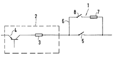
- the figure shows a protective circuit arrangement 1 in connection with a Brake chopper assembly 2 arranged in a DC circuit is.
- the brake chopper assembly 2 consists essentially of one Braking resistor 3 and one of them switching cyclically Power semiconductor 4. When the power semiconductor 4 is destroyed in one larger plant, the plant can continue to be operated. However, must the braking resistor 3 assigned to the defective power semiconductor 4 be switched off immediately, otherwise it could cause a fire can.
- Protective circuit arrangement 1 is provided for this.
- the Protective circuit arrangement 1 has a first AC switch 5, e.g. a GS contactor, which has one or more parallel contacts has the serial to the brake chopper assembly 2 are arranged.
- the first AC switch 5 is bypass-like from a current path 6 a fuse 7 and a second AC switch 8 bridges.
- the DC circuit must be opened, i.e. the first AC switch 5 is from the closed to the open Switch position moved.
- the switch current commutates to the parallel one Current path 6 with the fuse 7, so that no voltage on itself opening contact of the first AC switch 5 is induced and ultimately preventing the formation of an arc.
- the Fuse characteristic is chosen such that the melting time of the Fuse 7 is greater than the time that the first AC switch 5 needed for full opening. After the melting time is over Current path 6 separated. To be on the safe side, this will be Circuit breakage by the second AC switch 8 supported.
- This second AC switch 8 the rated current the fuse 7 is designed, the first AC switch 5 then operated when the AC switch 5 is fully opened and the fuse 7 has blown.
- the invention is not limited to the above Embodiment. Rather, a number of variants are possible which, even if the execution is fundamentally different, from the Make use of features of the invention.
Landscapes
- Engineering & Computer Science (AREA)
- Life Sciences & Earth Sciences (AREA)
- Sustainable Development (AREA)
- Sustainable Energy (AREA)
- Power Engineering (AREA)
- Transportation (AREA)
- Mechanical Engineering (AREA)
- Fuses (AREA)
- Emergency Protection Circuit Devices (AREA)
Abstract
Description
Die Erfindung betrifft eine Schutzschaltungsanordnung zum Auftrennen eines Gleichstromkreises. Gleichstromkreise, die nur zur Schutzzwecken , z.B. zur Verhinderung einer Brandgefahr bei einem defekten Bauelement, abgeschaltet werden müssen, sind dazu entweder mit einem entsprechenden Gleichstromschalter ausgestattet oder werden durch eine auf das gesamte Gerät- und nicht nur den defekten Gleichstromkreis - wirkende Sicherung abgeschaltet. Der Nachteil ersterer Lösung besteht darin, daß Gleichstromschaltgeräte sehr aufwendig und teuer sind, während bei letzterer Variante die Verfügbarkeit der Anlage sinkt, wobei eine Fehlerortung entsprechend schwierig ist.The invention relates to a protective circuit arrangement for disconnection a DC circuit. DC circuits used only for protection purposes, e.g. to prevent the risk of fire in the case of a defective component, must be switched off, either with a appropriate DC switch or are equipped with a on the entire device - and not just the defective DC circuit - active fuse switched off. The disadvantage of the former solution is in the fact that DC switching devices are very complex and expensive, while in the latter variant the availability of the system decreases, whereby fault location is correspondingly difficult.
Ein spezielles Einsatzgebiet einer solchen Schutzschaltung besteht bei einem Antrieb mehrachsiger Werkzeugmaschinen mittels einzelner Achssteller. Im Bremsbetrieb wird dabei Energie in einen Zwischenkreiskondensator geladen, so daß seine Spannung ansteigt. Um die Bauteile vor Überspannung zu schützen, wird parallel zum Zwischenkreis ein Widerstand geschaltet und dadurch ein Teil der Bremsenergie in Wärme umgesetzt. Der Widerstand wird immer dann zugeschaltet, wenn die Zwischenkreisspannung einen bestimmten Wert übersteigt, so daß sich eine bestimmte Schaltfrequenz ergibt. Man spricht deshalb auch von einem gepulsten Bremswiderstand oder von einem Brems-Chopper. Die Zuschaltung des Choppers erfolgt über einen Leistungshalbleiter, z.B. über einen IGBT. Ein Problem besteht bei defektem IGBT, weil dann wegen Brandgefahr eine unverzügliche Abschaltung des Gleichspannungszwischenkreises erfolgen muß.A special area of application for such a protective circuit is one Drive multi-axis machine tools by means of individual axis actuators. in the Braking is energy in an intermediate circuit capacitor charged so that its tension increases. To the components in front To protect overvoltage, a resistor becomes parallel to the intermediate circuit switched and thereby some of the braking energy is converted into heat. Of the Resistance is always switched on when the DC link voltage exceeds a certain value, so that a certain switching frequency results. One therefore speaks of one pulsed braking resistor or from a brake chopper. The The chopper is connected via a power semiconductor, e.g. about an IGBT. There is a problem with defective IGBT because it is because of Risk of fire if the DC voltage intermediate circuit must take place.
Im Hinblick auf den Massencharakter derartiger Schutzschaltungen und gestiegener Anforderungen an Sicherheitsstandards besteht die Aufgabe, einen kompakteren und preisgünstigeren Schaltungsaufbau für Schutzschaltungen universeller Anwendbarkeit anzugeben.With regard to the mass nature of such protective circuits and the increased requirements for security standards a more compact and less expensive circuit structure for Specify protection circuits of universal applicability.
Erfindungsgemäß erfolgt die Abschaltung des Gleichspannungskreises
gemäß den kennzeichnenden Merkmalen des Anspruchs 1, indem ein
erster Wechselstromschalter mit parallel geschalteter Sicherung als
Trennmittel verwendet wird.According to the invention, the DC voltage circuit is switched off
according to the characterizing features of
Wechselstromschalter, insbesondere Drehstromschütze, welche wesentlich kompakter und preisgünstiger sind als Gleichstromschalter, haben in der Regel nur ein sehr begrenztes Schaltvermögen für Gleichstrom. Die Ursache dafür liegt darin begründet, daß der beim Öffnen des Schaltkontaktes entstehende Lichtbogen nicht wie bei Wechselstrom im natürlichen Nulldurchgang des Stromes verlischt. Damit kein Lichtbogen entsteht, muß für die Zeitspanne, in der sich die Schaltkontakte aus der geschlossenen in die offene Schalterstellung bewegen, ein Bypass zum Schutzkontakt geschaffen werden, wobei eine Sicherung nach vollständigem Öffnen der Schutzkontakte den Strom selbsttätig unterbricht. Ein auf diese Weise geschalteter Drehstromschutz kann im Havariefall einen Gleichstromkreis abschalten. Der Nennstrom der Sicherung muß dem kleinsten im Stromkreis fließenden Gleichstrom entsprechen, um sicherzustellen, daß die Sicherung bereits bei kleinsten Strömen durchbrennt.AC switches, especially three-phase contactors, which are essential are more compact and cheaper than DC switches, have in the Usually only a very limited switching capacity for direct current. The cause the reason for this is that when the switch contact opens arcing does not occur as with alternating current in the natural Zero crossing of the current goes out. So that no arc arises, must for the period of time in which the switching contacts move from the closed in move the open switch position, a bypass to the protective contact be created, with a backup after fully opening the Protective contacts interrupt the current automatically. One this way switched three-phase current protection can a direct current circuit in the event of an accident switch off. The nominal current of the fuse must be the smallest in the circuit flowing direct current to ensure that the fuse blows even with the smallest currents.
Zusätzlich kann in Reihe zur Sicherung ein auf den Nennstrom der Sicherung ausgelegter zweiter Wechselstromschalter vorgesehen sein. Ein solcher als Trenner ohne Abschaltvermögen wirkender Wechselstromschalter bewirkt eine Trennung der Last bei abgeschaltetem Hauptschütz von dem Stromkreis. Der zweite Wechselstromschalter wird von dem ersten Wechselstromschalter (Hauptschütz) erst dann geöffnet, wenn dieser geöffnet ist und die Sicherung durchgebrannt ist.In addition, a fuse can be connected to the nominal current of the Fuse designed second AC switch may be provided. A such as a separator without breaking capacity AC switch disconnects the load when switched off Main contactor from the circuit. The second AC switch is from the first AC switch (main contactor) only opens when it is open and the fuse has blown.
Nachfolgend wird die Erfindung anhand eines figürlich dargestellten Ausführungsbeispiels näher erläutert.The invention is illustrated below with reference to a figure Embodiment explained in more detail.
Die Figur zeigt eine Schutzschaltungsanordnung 1 in Verbindung mit einer
Brems-Chopper-Baugruppe 2, die in einem Gleichstromkreis angeordnet
ist. Die Brems-Chopper-Baugruppe 2 besteht im wesentlichen aus einem
Bremswiderstand 3 und einem diesen taktweise schaltenden
Leistungshalbleiter 4. Bei Zerstörung des Leistungshalbleiters 4 in einer
größeren Anlage kann die Anlage weiter betrieben werden. Jedoch muß
der dem defekten Leistungshalbleiter 4 zugeordnete Bremswiderstand 3
unverzüglich abgeschaltet werden, da er sonst einen Brand hervorrufen
kann. Dazu ist die Schutzschaltungsanordnung 1 vorgesehen. Die
Schutzschaltungsanordnung 1 weist einen ersten Wechselstromschalter 5,
z.B. ein GS-Schütz auf, welches einen oder mehrere parallele Kontakte
besitzt die seriell zur Brems-Chopper-Baugruppe 2 angeordnet sind. Der
erste Wechselstromschalter 5 ist bypassartig von einem Strompfad 6 mit
einer Sicherung 7 und einem zweiten Wechselstromschalter 8 überbrückt. In
einem Havariefall muß der Gleichstromkreis geöffnet werden, d.h. der erste
Wechselstromschalter 5 wird aus der geschlossenen in die offene
Schalterstellung bewegt. Der Schalterstrom kommutiert auf den parallelen
Strompfad 6 mit der Sicherung 7, so daß keine Spannung am sich
öffnenden Kontakt des ersten Wechselstromschalters 5 induziert wird und
letztlich die Entstehung eines Lichtbogen verhindert wird. Die
Sicherungscharakteristik ist derart gewählt, daß die Schmelzzeit der
Sicherung 7 größer ist als die Zeit, die der erste Wechselstromschalter 5
zum vollständigen Öffnen benötigt. Nach Ablauf der Schmelzzeit ist der
Strompfad 6 aufgetrennt. Sicherheitshalber wird diese
Stromkreisunterbrechung durch den zweiten Wechselstromschalter 8
unterstützt. Dieser zweite Wechselstromschalter 8, der auf den Nennstrom
der Sicherung 7 ausgelegt ist, wird von dem ersten Wechselstromschalter 5
dann betätigt, wenn der Wechselstromschalter 5 vollständig geöffnet und
die Sicherung 7 durchgebrannt ist.The figure shows a
Die Erfindung beschränkt sich nicht auf das vorstehend angegebene Ausführungsbeispiel. Vielmehr ist eine Anzahl von Varianten möglich, welche auch bei grundsätzlich anders gearteter Ausführung von den Merkmalen der Erfindung Gebrauch machen.The invention is not limited to the above Embodiment. Rather, a number of variants are possible which, even if the execution is fundamentally different, from the Make use of features of the invention.
Claims (3)
Applications Claiming Priority (2)
| Application Number | Priority Date | Filing Date | Title |
|---|---|---|---|
| DE1998124269 DE19824269A1 (en) | 1998-05-29 | 1998-05-29 | Protective circuit arrangement for disconnecting a direct current circuit |
| DE19824269 | 1998-05-29 |
Publications (2)
| Publication Number | Publication Date |
|---|---|
| EP0961380A2 true EP0961380A2 (en) | 1999-12-01 |
| EP0961380A3 EP0961380A3 (en) | 2000-10-18 |
Family
ID=7869431
Family Applications (1)
| Application Number | Title | Priority Date | Filing Date |
|---|---|---|---|
| EP99107487A Withdrawn EP0961380A3 (en) | 1998-05-29 | 1999-04-29 | Protection circuit arrangement for disconnecting a direct current circuit |
Country Status (2)
| Country | Link |
|---|---|
| EP (1) | EP0961380A3 (en) |
| DE (1) | DE19824269A1 (en) |
Cited By (2)
| Publication number | Priority date | Publication date | Assignee | Title |
|---|---|---|---|---|
| EP1300919A1 (en) * | 2001-10-08 | 2003-04-09 | LEONI Bordnetz-Systeme GmbH & Co KG | Electrical network and method for protecting the network against electrical arcs |
| WO2019115714A1 (en) * | 2017-12-15 | 2019-06-20 | Bayerische Motoren Werke Aktiengesellschaft | Separating device for a high-voltage electrical system of a motor vehicle, high-voltage electrical system, and motor vehicle |
Families Citing this family (1)
| Publication number | Priority date | Publication date | Assignee | Title |
|---|---|---|---|---|
| DE102013012578B4 (en) * | 2013-07-30 | 2023-10-05 | Lisa Dräxlmaier GmbH | Device for securing an electrical line and method for operating a device arranged on an electrical line |
Family Cites Families (5)
| Publication number | Priority date | Publication date | Assignee | Title |
|---|---|---|---|---|
| US3544843A (en) * | 1967-12-19 | 1970-12-01 | Westinghouse Electric Corp | High-voltage direct current circuit interrupter |
| DE2906556C2 (en) * | 1979-02-17 | 1984-04-26 | Licentia Patent-Verwaltungs-Gmbh, 6000 Frankfurt | Overcurrent protection arrangement in the event of incorrect summing of a thyristor inverter of a crossover converter |
| JPH03135385A (en) * | 1989-10-18 | 1991-06-10 | Fuji Electric Co Ltd | Method of protecting overheat of damping resistor |
| EP0450126B1 (en) * | 1990-04-06 | 1994-02-16 | Siemens Aktiengesellschaft | Protection and monitoring device for a pulse resistor of a voltage intermediate circuit converter |
| AT397003B (en) * | 1992-01-16 | 1994-01-25 | Holly Rudolf | DEVICE FOR DISCONNECTING A HIGH VOLTAGE CIRCUIT |
-
1998
- 1998-05-29 DE DE1998124269 patent/DE19824269A1/en not_active Ceased
-
1999
- 1999-04-29 EP EP99107487A patent/EP0961380A3/en not_active Withdrawn
Cited By (5)
| Publication number | Priority date | Publication date | Assignee | Title |
|---|---|---|---|---|
| EP1300919A1 (en) * | 2001-10-08 | 2003-04-09 | LEONI Bordnetz-Systeme GmbH & Co KG | Electrical network and method for protecting the network against electrical arcs |
| US6912110B2 (en) | 2001-10-08 | 2005-06-28 | Leoni Bordnetz-Systeme | Cable network and method for protecting the cable network against a serial arc |
| WO2019115714A1 (en) * | 2017-12-15 | 2019-06-20 | Bayerische Motoren Werke Aktiengesellschaft | Separating device for a high-voltage electrical system of a motor vehicle, high-voltage electrical system, and motor vehicle |
| CN111201687A (en) * | 2017-12-15 | 2020-05-26 | 宝马股份公司 | Disconnecting device for high-voltage on-board electrical system of a motor vehicle, high-voltage on-board electrical system and motor vehicle |
| US11440412B2 (en) | 2017-12-15 | 2022-09-13 | Bayerische Motoren Werke Aktiengesellschaft | Disconnection device for a high-voltage electrical system of a motor vehicle, high-voltage electrical system, and motor vehicle |
Also Published As
| Publication number | Publication date |
|---|---|
| DE19824269A1 (en) | 1999-12-02 |
| EP0961380A3 (en) | 2000-10-18 |
Similar Documents
| Publication | Publication Date | Title |
|---|---|---|
| EP3987559B1 (en) | Protective switching device, protective interrupting system and method therefor | |
| EP2048679B1 (en) | Circuit breaker assembly | |
| DE2710159C2 (en) | ||
| EP3091550A1 (en) | Hybrid switching device | |
| DE102015226475A1 (en) | switching device | |
| DE2612922C2 (en) | Diverter switch for step transformers, each with a pair of anti-parallel connected thyristors in each of the two load branches | |
| DE19711622C1 (en) | Method of running an electrical load, such as contactor or load-relay, connected into a circuit | |
| EP0453776B1 (en) | Switchgear with a circuit breaker or a load break switch and a fuse | |
| EP0961380A2 (en) | Protection circuit arrangement for disconnecting a direct current circuit | |
| EP3771053A1 (en) | Arcing fault monitoring device, particularly for low-voltage switchgear | |
| DE4005532A1 (en) | Generator load switch for power plant - uses standard vacuum breaker switches controlled via zero transition relay | |
| EP0126882A2 (en) | Switchgear equipment for electrical energy distribution, and method to operate the switchgear equipment | |
| DE2702181C3 (en) | Short-circuit protection circuit for devices that can be switched on or off via semiconductor switches, in particular for light control devices | |
| DE102019213390A1 (en) | Method for controlling an electrical switch | |
| LU505555B1 (en) | Disconnector | |
| EP0613427B1 (en) | Circuitry for rectifier substations | |
| DE3926990C2 (en) | Network switching facility | |
| DE4023238A1 (en) | CIRCUIT ARRANGEMENT WITH A TRANSFORMER | |
| DE745234C (en) | High voltage switchgear | |
| DE19528020A1 (en) | Self-monitoring residual current circuit breaker | |
| EP0844632A2 (en) | Contact arrangement for ground fault circuit interrupter | |
| DE1640053A1 (en) | Fuse monitoring for fuse disconnector | |
| DD144844A1 (en) | METHOD AND DEVICE FOR SHUT-OFF OF SHORT-TERM STREAMS | |
| DE2925109A1 (en) | METHOD FOR SHUTDING OFF SHORT CIRCUIT CURRENTS IN ELECTRIC HIGH VOLTAGE SYSTEMS AND DEVICE FOR CARRYING OUT THIS | |
| DE3709107A1 (en) | ARRANGEMENT FOR CONTROLLING A STAR TRIANGLE PROTECTION COMBINATION |
Legal Events
| Date | Code | Title | Description |
|---|---|---|---|
| PUAI | Public reference made under article 153(3) epc to a published international application that has entered the european phase |
Free format text: ORIGINAL CODE: 0009012 |
|
| AK | Designated contracting states |
Kind code of ref document: A2 Designated state(s): CH DE FR GB LI |
|
| AX | Request for extension of the european patent |
Free format text: AL;LT;LV;MK;RO;SI |
|
| PUAL | Search report despatched |
Free format text: ORIGINAL CODE: 0009013 |
|
| AK | Designated contracting states |
Kind code of ref document: A3 Designated state(s): AT BE CH CY DE DK ES FI FR GB GR IE IT LI LU MC NL PT SE |
|
| AX | Request for extension of the european patent |
Free format text: AL;LT;LV;MK;RO;SI |
|
| RIC1 | Information provided on ipc code assigned before grant |
Free format text: 7H 02H 3/087 A, 7B 60L 3/00 B |
|
| RAP1 | Party data changed (applicant data changed or rights of an application transferred) |
Owner name: ALSTOM POWER CONVERSION GMBH |
|
| 17P | Request for examination filed |
Effective date: 20001215 |
|
| AKX | Designation fees paid |
Free format text: CH DE FR GB LI |
|
| STAA | Information on the status of an ep patent application or granted ep patent |
Free format text: STATUS: THE APPLICATION HAS BEEN WITHDRAWN |
|
| 18W | Application withdrawn |
Effective date: 20040403 |