EP0961099A2 - Zündeinrichtung für Penetratoren - Google Patents
Zündeinrichtung für Penetratoren Download PDFInfo
- Publication number
- EP0961099A2 EP0961099A2 EP99110091A EP99110091A EP0961099A2 EP 0961099 A2 EP0961099 A2 EP 0961099A2 EP 99110091 A EP99110091 A EP 99110091A EP 99110091 A EP99110091 A EP 99110091A EP 0961099 A2 EP0961099 A2 EP 0961099A2
- Authority
- EP
- European Patent Office
- Prior art keywords
- signal
- time
- evaluation
- signals
- ignition
- Prior art date
- Legal status (The legal status is an assumption and is not a legal conclusion. Google has not performed a legal analysis and makes no representation as to the accuracy of the status listed.)
- Granted
Links
- 238000011156 evaluation Methods 0.000 claims abstract description 27
- 238000012545 processing Methods 0.000 claims abstract description 11
- 238000012935 Averaging Methods 0.000 claims abstract description 9
- 230000001133 acceleration Effects 0.000 claims abstract description 8
- 230000015572 biosynthetic process Effects 0.000 claims description 6
- 230000010354 integration Effects 0.000 claims 1
- 238000005259 measurement Methods 0.000 abstract description 2
- 230000004913 activation Effects 0.000 abstract 1
- 238000012854 evaluation process Methods 0.000 abstract 1
- 238000004519 manufacturing process Methods 0.000 abstract 1
- 238000010586 diagram Methods 0.000 description 6
- 230000003044 adaptive effect Effects 0.000 description 2
- 230000035515 penetration Effects 0.000 description 2
- 230000009286 beneficial effect Effects 0.000 description 1
- 239000003795 chemical substances by application Substances 0.000 description 1
- 230000000694 effects Effects 0.000 description 1
- 239000002360 explosive Substances 0.000 description 1
- 238000001914 filtration Methods 0.000 description 1
- 238000013517 stratification Methods 0.000 description 1
- 238000012360 testing method Methods 0.000 description 1
- 230000001960 triggered effect Effects 0.000 description 1
Images


Classifications
-
- F—MECHANICAL ENGINEERING; LIGHTING; HEATING; WEAPONS; BLASTING
- F42—AMMUNITION; BLASTING
- F42C—AMMUNITION FUZES; ARMING OR SAFETY MEANS THEREFOR
- F42C11/00—Electric fuzes
- F42C11/06—Electric fuzes with time delay by electric circuitry
Definitions
- the invention relates to an ignition device for penetrators, which Transducers for acceleration forces, as well as an evaluation circuit for Processing of the pickup signals, with the evaluation Signals are compared with signal thresholds and where at their Output signals are exceeded.
- the invention has for its object a device the adaptive ignition of a penetrator to create penetration evaluates different layers of coverage of a target and one Triggering within a certain shift or after passing through made possible by a particular layer, with the target under another soft layer can be arranged.
- a circuit can be generated with little effort that are versatile to different applications with known Stratifications can be adjusted. Possibly existing soft Layers that serve, for example, to camouflage the target do not lead to Release. If the layer structure is not known, it can reliable in a particular shift or after going through them all Layers are triggered. The zero point error of the Accelerometer and its time drift are in the chosen type of assessment largely uncritical. Interference signals, especially those caused by body vibrations of the penetrator caused, affect the evaluation result due to the Averaging of the signals only insignificant.
- the signal curve 1 in FIG. 1 shows a typical course of the output signal of the accelerometer B from FIG. 2 after filtering by means of the bandpass filter BP.
- the two successive impulses come from the penetration of the penetrator through two hard layers of target coverage. In between a weak signal can be seen, which comes from the passage through a soft layer.
- On the time axis, which is arranged below the signal curve two time windows t 1 ... t 2 and t 3 ... t 4 can be seen, which have a time interval t 2 ... t 3 .
- the signal curve 1 runs through the two time windows, the signal contents of the two time windows are each evaluated at successive times.
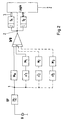
- FIG. 2 shows a simplified schematic block diagram of a signal evaluation according to the invention.
- the ignition device is started up with the occurrence of certain events, such as the start of the penetrator or when it hits a target, the start-up not having to take place exactly when the event occurs, but also before or after it.
- the output signal of the accelerometer B is first filtered in the bandpass filter BP in order to eliminate the undesired low and high frequency components of the signal.
- the resulting sensor signal is shown in FIG. 1 and FIG. 3 as signal curve 1.
- This signal 1 is then fed to at least two signal processing branches M 0 and ⁇ T 1 , M 1 .
- ⁇ T 1 t 3rd - t 1 .
- Averaging takes place in the first branch M 0 during the time window t 1 ... t 2 .
- the averaging in the time window t 3 ... t 4 is only carried out after a selectable delay time ⁇ T 1 .
- the signal curve 2 in FIG. 3 shows the typical course of a signal averaged in this way.
- the curve shape is the result of the summation of the signal contents of the signal curve 1 within the time window t 1 ... t 2 and t 3 ... t 4 in the summer S / D.
- the signal curve was limited to a certain maximum signal level.
- the length of the time window and the time difference between the start times are set in each case from the data of the airspeed known before the start and the layer structure of the destination. Typical values of a test arrangement are in the range from 1 to 10 ms.
- additional branches ⁇ T 2 , M 2 and ⁇ T 3 , M 3 are optionally provided.
- additional time windows for averaging the pickup signal 1 can additionally be provided, which begin one after the other at different times.
- the time windows can be spaced apart or even partially overlap. The position of the time window is set depending on the previously known conditions of the application.
- the evaluated signals 2 are then compared with signal thresholds S 1 and S 2 , the output signals of which are fed to a logic for evaluation.
- signal 2 can also be made available directly to the logic.
- the signal arrows pointing in both directions between the signal thresholds S 1 , S 2 and the logic indicate that the signal thresholds can also be influenced by the logic. It is also conceivable to use multi-level sleepers. From this, the signal amplitudes can be distinguished and evaluated more precisely. This also separates the soft from the hard layers of a target cover.
- the incoming signals of a time and / or subjected to event-related assessment This means that the signals both with regard to their position with regard to the time of impact with the Goal, as well as regarding the relative position of the impulses to each other and be evaluated with regard to the sign of the impulses.
- the Signal curve 3 in FIG. 3 shows an example of such a pulse train, which consists of the averaged signal (curve 2 in FIG. 3) by means of the evaluation by the Thresholds 4 and 5 have arisen and are then evaluated in the logic. It can be seen here that both the type of acceleration or Delay on the sign of the pulses can be evaluated, as well Position of the impulses with regard to the time of impact and the position of the impulses among themselves as a representation of entry and exit different layers of the target.
- the logic finally gives depending on the given logical link the timing or event-related signals an ignition signal Z to the Agents of the penetrator.
- the type of logical link can be used for the case that the layers to be penetrated are known accordingly to get voted. In other cases, the link is chosen so that the greatest possible effect can be achieved.
- FIG. 4 shows a block diagram of a schematically simplified diagram digital signal evaluation according to the invention.
- the analog and i.a. prefiltered output signal of the accelerometer B first by means of an analog / digital converter A / D into digital pulses converted.
- the digitized signal is in a shift register SR headed.
- the shift register SR is in the drawing in three blocks divided, which symbolically stand for periods in which older or younger signal components can be selected. So that includes Shift register block, which is directly connected to the analog / digital converter A / D follows the most recent portion of the pickup signal, while that block, closest to the signal processing circuit ALU, the oldest Contains part of the transducer signal.
- the averaging and the summation or difference formation takes place in a signal processing circuit ALU, for example as Microcomputer can be realized.
- ALU signal processing circuit
- the output signal of the Signal processing circuit is fed to the comparators K, whose Output signals of a logic are provided as input variables become. There these signals are time and / or event related logically linked. This in turn becomes an ignition signal Z generated.
- the processing of the output signals of the accelerometer B can alternatively also be carried out by integrating the signals within the time segments t 1 ... t 2 and t 3 ... t 4 instead of averaging.
- the determined contents of the integrals are then subjected to an evaluation (S / D, ALU) in that the differences of successive integral contents are formed in each case.
- the further signal processing is carried out analogously to that with averaging, so that a detailed description can be dispensed with here.
Landscapes
- Engineering & Computer Science (AREA)
- General Engineering & Computer Science (AREA)
- Geophysics And Detection Of Objects (AREA)
- Ignition Installations For Internal Combustion Engines (AREA)
- Aiming, Guidance, Guns With A Light Source, Armor, Camouflage, And Targets (AREA)
Abstract
Description
- Fig. 1
- das Ausgangssignal des Beschleunigungsaufnehmers
- Fig. 2
- ein Blockschaltbild zur analogen Auswertung des Aufnehmersignals
- Fig. 3
- typische Signalverläufe im Blockschaltbild gemäß Fig. 2
- Fig. 4
- ein Blockschaltbild zur digitalen Auswertung des Aufnehmersignals
Claims (20)
- Zündeinrichtung für Penetratoren, welche Aufnehmer für Beschleunigungskräfte, sowie eine Auswerteschaltung zur Verarbeitung der Aufnehmersignale aufweist, wobei bei der Bewertung Signale mit Signalschwellen verglichen werden und wobei bei deren Überschreitung Ausgangssignale erzeugt werden,
gekennzeichnet durch folgende Merkmale:nach erfolgter Inbetriebnahme der Zündeinrichtung des Penetrators beginnen Meßzyklen, die sich fortlaufend wiederholen,innerhalb jedes der Meßzyklen wird das Ausgangssignal des Beschleunigungsaufnehmers (B) in mindestens zwei Zeitabschnitten (t1 ... t2; t3 ... t4), die zeitlich zueinander versetzt beginnen, einer Mittelwertbildung (M) unterzogen,die in den Zeitabschnitten (t1 ... t2; t3 ... t4) gemessenen Mittelwerte werden anschließend einer Bewertung (S/D, ALU) unterworfen,die Ausgangsgrößen (2) der Bewertung (S/D, ALU) werden zeit- und/oder ereignisbezogen logisch miteinander verknüpft, wobei aus der Verknüpfung (LOGIK) ein Zündsignal (Z) abgeleitet wird. - Einrichtung nach Anspruch 1, dadurch gekennzeichnet, daß das Aufnehmerausgangssignal über einen Bandpaß (BP) geführt wird.
- Einrichtung nach Anspruch 1 oder 2, dadurch gekennzeichnet, daß die Zeitabschnitte (t1 ... t2; t3 ... t4) eine Länge aufweisen, die in Abhängigkeit von der Geschwindigkeit und/oder den zu durchdringenden Schichtdicken einstellbar ist.
- Einrichtung nach Anspruch 3, dadurch gekennzeichnet, daß die Zeitabschnitte (t1 ... t2, t3 t4) eine Länge von wenigen Millisekunden aufweisen.
- Einrichtung nach wenigstens einem der Ansprüche 1 bis 4, dadurch gekennzeichnet, daß die Zeitdifferenz zwischen den Startzeitpunkten (t1, t3) eine Länge aufweist, die in Abhängigkeit von der Geschwindigkeit und/oder den zu durchdringenden Schichtdicken einstellbar ist.
- Einrichtung nach Anspruch 5, dadurch gekennzeichnet, daß die Zeitdifferenz zwischen den Startzeitpunkten (t1; t3) zweier aufeinander folgender Zeitintervalle wenige Millisekunden beträgt.
- Einrichtung nach wenigstens einem der Ansprüche 1 bis 6, dadurch gekennzeichnet, daß die Bewertung der Mittelwerte (M) mittels Summation und/oder Differenzbildung der den jeweiligen Zeitabschnitten zugeordneten Mittelwerte erfolgt.
- Einrichtung nach Anspruch 7, dadurch gekennzeichnet, daß die Bewertung der Ergebnisse der Summation bzw. Differenzbildung mittels Signalschwellen (S1, S2) oder Komparatoren (K) erfolgt.
- Einrichtung nach Anspruch 7, dadurch gekennzeichnet, daß die Ergebnisse der Summation bzw. Differenzbildung einer Gewichtung unterzogen werden.
- Einrichtung nach Anspruch 9, dadurch gekennzeichnet, daß die Gewichtung mittels jeweils einer Verstärkerstufe mit einstellbarer Verstärkung erfolgt.
- Zündeinrichtung für Penetratoren, welche Aufnehmer für Beschleunigungskräfte, sowie eine Auswerteschaltung zur Verarbeitung der Aufnehmersignale aufweist, wobei bei der Bewertung Signale mit Signalschwellen verglichen werden und wobei bei deren Überschreitung Ausgangssignale erzeugt werden,
gekennzeichnet durch folgende Merkmale:nach erfolgter Inbetriebnahme der Zündeinrichtung des Penetrators beginnen Meßzyklen, die sich fortlaufend wiederholen,innerhalb jedes der Meßzyklen wird das Ausgangssignal des Beschleunigungsaufnehmers (B) in mindestens zwei Zeitabschnitten (t1 ... t2; t3 ... t4), die zeitlich zueinander versetzt beginnen, einer Integration unterzogen,die in den Zeitabschnitten (t1 ... t2; t3 ... t4) ermittelten Integrale werden anschließend einer Bewertung (S/D, ALU) unterworfen,die Ausgangsgrößen (2) der Bewertung (S/D, ALU) werden zeit- und/oder ereignisbezogen logisch miteinander verknüpft, wobei aus der Verknüpfung (LOGIK) ein Zündsignal (Z) abgeleitet wird. - Einrichtung nach Anspruch 11, dadurch gekennzeichnet, daß das Aufnehmerausgangssignal über einen Bandpaß (BP) geführt wird.
- Einrichtung nach Anspruch 11 oder 12, dadurch gekennzeichnet, daß die Zeitabschnitte (t1 ... t2; t3 ... t4) eine Länge aufweisen, die in Abhängigkeit von der Geschwindigkeit und/oder den zu durchdringenden Schichtdicken einstellbar ist.
- Einrichtung nach Anspruch 13, dadurch gekennzeichnet, daß die Zeitabschnitte (t1 ... t2, t3 ... t4) eine Länge von wenigen Millisekunden aufweisen.
- Einrichtung nach wenigstens einem der Ansprüche 11 bis 14, dadurch gekennzeichnet, daß die Zeitdifferenz zwischen den Startzeitpunkten (t1, t3) eine Länge aufweist, die in Abhängigkeit von der Geschwindigkeit und/oder den zu durchdringenden Schichtdicken einstellbar ist.
- Einrichtung nach Anspruch 15, dadurch gekennzeichnet, daß die Zeitdifferenz zwischen den Startzeitpunkten (t1; t3) zweier aufeinander folgender Zeitintervalle wenige Millisekunden beträgt.
- Einrichtung nach wenigstens einem der Ansprüche 11 bis 16, dadurch gekennzeichnet, daß die Bewertung der Integrale mittels Differenzbildung der den jeweiligen Zeitabschnitten zugeordneten Integralinhalte erfolgt.
- Einrichtung nach Anspruch 17, dadurch gekennzeichnet, daß die Bewertung der Ergebnisse der Differenzbildung mittels Signalschwellen (S1, S2) oder Komparatoren (K) erfolgt.
- Einrichtung nach Anspruch 17, dadurch gekennzeichnet, daß die Ergebnisse der Differenzbildung einer Gewichtung unterzogen werden.
- Einrichtung nach Anspruch 19, dadurch gekennzeichnet, daß die Gewichtung mittels jeweils einer Verstärkerstufe mit einstellbarer Verstärkung erfolgt.
Applications Claiming Priority (4)
| Application Number | Priority Date | Filing Date | Title |
|---|---|---|---|
| DE19823795 | 1998-05-28 | ||
| DE19823795 | 1998-05-28 | ||
| DE19854608A DE19854608C2 (de) | 1998-05-28 | 1998-11-26 | Zündeinrichtung für Penetratoren |
| DE19854608 | 1998-11-26 |
Publications (3)
| Publication Number | Publication Date |
|---|---|
| EP0961099A2 true EP0961099A2 (de) | 1999-12-01 |
| EP0961099A3 EP0961099A3 (de) | 2000-08-23 |
| EP0961099B1 EP0961099B1 (de) | 2003-03-19 |
Family
ID=26046462
Family Applications (1)
| Application Number | Title | Priority Date | Filing Date |
|---|---|---|---|
| EP19990110091 Expired - Lifetime EP0961099B1 (de) | 1998-05-28 | 1999-05-22 | Zündeinrichtung für Penetratoren |
Country Status (2)
| Country | Link |
|---|---|
| EP (1) | EP0961099B1 (de) |
| ES (1) | ES2190149T3 (de) |
Cited By (3)
| Publication number | Priority date | Publication date | Assignee | Title |
|---|---|---|---|---|
| EP2407748A2 (de) | 2010-07-15 | 2012-01-18 | TDW Gesellschaft für verteidigungstechnische Wirksysteme mbH | Messverfahren für einen Penetratorzünder |
| DE102010027191A1 (de) | 2010-07-15 | 2012-01-19 | TDW Gesellschaft für verteidigungstechnische Wirksysteme mbH | Verfahren zur Optimierung der Auslösegenauigkeit eines Penetratorzünders |
| WO2020246939A1 (en) * | 2019-06-01 | 2020-12-10 | Advanced Material Engineering Pte Ltd | Safe-and-arm fuzing method for a projectile |
Citations (1)
| Publication number | Priority date | Publication date | Assignee | Title |
|---|---|---|---|---|
| DE3426547C2 (de) | 1984-07-19 | 1987-10-22 | Messerschmitt-Boelkow-Blohm Gmbh, 8012 Ottobrunn, De |
Family Cites Families (5)
| Publication number | Priority date | Publication date | Assignee | Title |
|---|---|---|---|---|
| DE2528770A1 (de) * | 1975-06-27 | 1977-01-13 | Messerschmitt Boelkow Blohm | Einrichtung zur vorrohrsicherung eines zuenders |
| US4375192A (en) * | 1981-04-03 | 1983-03-01 | The United States Of America As Represented By The Secretary Of The Navy | Programmable fuze |
| FR2646504B1 (fr) * | 1989-04-28 | 1994-03-25 | Thomson Brandt Armements | Processeur d'impact pour munition |
| DE4025563C1 (en) * | 1990-08-11 | 1991-05-23 | Messerschmitt-Boelkow-Blohm Gmbh, 8012 Ottobrunn, De | Detonator for underwater projectile - has electrical circuit with acceleration sensor output signal fed to two threshold valve switches via band pass filter |
| US5255608A (en) * | 1992-12-16 | 1993-10-26 | The United States Of America As Represented By The Secretary Of The Air Force | Real-time identification of a medium for a high-speed penetrator |
-
1999
- 1999-05-22 ES ES99110091T patent/ES2190149T3/es not_active Expired - Lifetime
- 1999-05-22 EP EP19990110091 patent/EP0961099B1/de not_active Expired - Lifetime
Patent Citations (1)
| Publication number | Priority date | Publication date | Assignee | Title |
|---|---|---|---|---|
| DE3426547C2 (de) | 1984-07-19 | 1987-10-22 | Messerschmitt-Boelkow-Blohm Gmbh, 8012 Ottobrunn, De |
Cited By (6)
| Publication number | Priority date | Publication date | Assignee | Title |
|---|---|---|---|---|
| EP2407748A2 (de) | 2010-07-15 | 2012-01-18 | TDW Gesellschaft für verteidigungstechnische Wirksysteme mbH | Messverfahren für einen Penetratorzünder |
| DE102010027191A1 (de) | 2010-07-15 | 2012-01-19 | TDW Gesellschaft für verteidigungstechnische Wirksysteme mbH | Verfahren zur Optimierung der Auslösegenauigkeit eines Penetratorzünders |
| DE102010034464A1 (de) | 2010-07-15 | 2012-01-19 | TDW Gesellschaft für verteidigungstechnische Wirksysteme mbH | Messverfahren für einen Penetratorzünder |
| DE102010034464B4 (de) * | 2010-07-15 | 2012-04-19 | TDW Gesellschaft für verteidigungstechnische Wirksysteme mbH | Messverfahren für einen Penetratorzünder |
| DE102010027191B4 (de) * | 2010-07-15 | 2014-02-27 | TDW Gesellschaft für verteidigungstechnische Wirksysteme mbH | Verfahren zur Optimierung der Auslösegenauigkeit eines Penetratorzünders |
| WO2020246939A1 (en) * | 2019-06-01 | 2020-12-10 | Advanced Material Engineering Pte Ltd | Safe-and-arm fuzing method for a projectile |
Also Published As
| Publication number | Publication date |
|---|---|
| EP0961099B1 (de) | 2003-03-19 |
| EP0961099A3 (de) | 2000-08-23 |
| ES2190149T3 (es) | 2003-07-16 |
Similar Documents
| Publication | Publication Date | Title |
|---|---|---|
| DE4141468C2 (de) | Optische Sensoranordnung und Verfahren zu deren Betrieb | |
| DE4213673C2 (de) | Auslöseverfahren für ein Rückhaltesystem | |
| DE69829391T2 (de) | Verbindungsverfahren zwischen zielverfolgungsbahnen | |
| EP3084465B1 (de) | Verfahren zur verarbeitung eines echosignals eines ultraschallwandlers | |
| WO2014108300A1 (de) | Vorrichtung und verfahren zur umfeldsensorik | |
| DE2710877C2 (de) | Einbruch-Alarmsystem | |
| DE3020996C2 (de) | Einrichtung zur Bestimmung der Auslöseentfernung von einem sich auf ein Ziel zu bewegenden Flugkörper | |
| DE3606567A1 (de) | Pruefverfahren fuer airbag-system-ausloeseschaltungen | |
| DE19754220B4 (de) | Verfahren und Vorrichtung zur Erkennung einer bevorstehenden oder möglichen Kollision | |
| EP0128543A1 (de) | Puls-Doppler-Radargerät mit veränderbarer Pulsfolgefrequenz | |
| DE69427319T2 (de) | System zur Detektion von modulierten Lasersignalen | |
| DE2305917A1 (de) | Verfahren zum korrigieren zufaelliger laufzeitmessfehler einer akustischen welle in bohrlochdurchteuften erdformationen und anordnung zur durchfuehrung des verfahrens | |
| DE3004605A1 (de) | Verfahren zur messung des ventilspiels einer brennkraftmaschine | |
| EP0961099B1 (de) | Zündeinrichtung für Penetratoren | |
| EP0777130B1 (de) | Digitales Verfahren zur Detektion zeitlich kurzer Pulse und Anordnung zur Durchführung des Verfahrens | |
| DE19854608C2 (de) | Zündeinrichtung für Penetratoren | |
| DE3020853A1 (de) | Verfahren zur erkennung des klopfens einer brennkraftmaschine und vorrichtung zur durchfuehrung des verfahrens | |
| DE3622371C2 (de) | ||
| DE102004049380B4 (de) | Fahrzeugsensor | |
| DE4237721B4 (de) | Verfahren und Vorrichtung zur Identifizierung von Verkehrsteilnehmern | |
| EP0789252B1 (de) | Verfahren zur Unterdrückung von Störsignalen bei einem Pulsdopplerradar | |
| DE3502399C1 (de) | Elektronische Vorrichtung für Gegen-Gegenmaßnahmen bei einem Kohärent-Impuls-Radarempfänger | |
| DE4210797A1 (de) | Verfahren und Schaltungsanordnung zur Überwachung einer Leitung für ein impulsförmiges Signal | |
| EP2407748A2 (de) | Messverfahren für einen Penetratorzünder | |
| DE2801333A1 (de) | Schaltungsanordnung zum empfang von echosignalen in einer echolotanlage |
Legal Events
| Date | Code | Title | Description |
|---|---|---|---|
| PUAI | Public reference made under article 153(3) epc to a published international application that has entered the european phase |
Free format text: ORIGINAL CODE: 0009012 |
|
| AK | Designated contracting states |
Kind code of ref document: A2 Designated state(s): DE ES FR GB GR IT SE |
|
| AX | Request for extension of the european patent |
Free format text: AL;LT;LV;MK;RO;SI |
|
| PUAL | Search report despatched |
Free format text: ORIGINAL CODE: 0009013 |
|
| AK | Designated contracting states |
Kind code of ref document: A3 Designated state(s): AT BE CH CY DE DK ES FI FR GB GR IE IT LI LU MC NL PT SE |
|
| AX | Request for extension of the european patent |
Free format text: AL;LT;LV;MK;RO;SI |
|
| RAP1 | Party data changed (applicant data changed or rights of an application transferred) |
Owner name: EADS DEUTSCHLAND GMBH |
|
| AKX | Designation fees paid |
Free format text: DE ES FR GB GR IT SE |
|
| 17P | Request for examination filed |
Effective date: 20010113 |
|
| 17Q | First examination report despatched |
Effective date: 20020123 |
|
| GRAH | Despatch of communication of intention to grant a patent |
Free format text: ORIGINAL CODE: EPIDOS IGRA |
|
| GRAH | Despatch of communication of intention to grant a patent |
Free format text: ORIGINAL CODE: EPIDOS IGRA |
|
| RAP1 | Party data changed (applicant data changed or rights of an application transferred) |
Owner name: TDW GESELLSCHAFT FUER VERTEIDIGUNGSTECHNISCHE WIRK |
|
| GRAA | (expected) grant |
Free format text: ORIGINAL CODE: 0009210 |
|
| AK | Designated contracting states |
Designated state(s): DE ES FR GB GR IT SE |
|
| PG25 | Lapsed in a contracting state [announced via postgrant information from national office to epo] |
Ref country code: GR Free format text: LAPSE BECAUSE OF FAILURE TO SUBMIT A TRANSLATION OF THE DESCRIPTION OR TO PAY THE FEE WITHIN THE PRESCRIBED TIME-LIMIT Effective date: 20030319 |
|
| REG | Reference to a national code |
Ref country code: GB Ref legal event code: FG4D Free format text: NOT ENGLISH |
|
| PGFP | Annual fee paid to national office [announced via postgrant information from national office to epo] |
Ref country code: GR Payment date: 20030422 Year of fee payment: 5 |
|
| REF | Corresponds to: |
Ref document number: 59904591 Country of ref document: DE Date of ref document: 20030424 Kind code of ref document: P |
|
| REG | Reference to a national code |
Ref country code: SE Ref legal event code: TRGR |
|
| GBT | Gb: translation of ep patent filed (gb section 77(6)(a)/1977) | ||
| REG | Reference to a national code |
Ref country code: ES Ref legal event code: FG2A Ref document number: 2190149 Country of ref document: ES Kind code of ref document: T3 |
|
| ET | Fr: translation filed | ||
| PLBE | No opposition filed within time limit |
Free format text: ORIGINAL CODE: 0009261 |
|
| STAA | Information on the status of an ep patent application or granted ep patent |
Free format text: STATUS: NO OPPOSITION FILED WITHIN TIME LIMIT |
|
| 26N | No opposition filed |
Effective date: 20031222 |
|
| PGFP | Annual fee paid to national office [announced via postgrant information from national office to epo] |
Ref country code: ES Payment date: 20100525 Year of fee payment: 12 |
|
| PGFP | Annual fee paid to national office [announced via postgrant information from national office to epo] |
Ref country code: IT Payment date: 20100522 Year of fee payment: 12 |
|
| PGFP | Annual fee paid to national office [announced via postgrant information from national office to epo] |
Ref country code: SE Payment date: 20100517 Year of fee payment: 12 |
|
| REG | Reference to a national code |
Ref country code: SE Ref legal event code: EUG |
|
| PG25 | Lapsed in a contracting state [announced via postgrant information from national office to epo] |
Ref country code: IT Free format text: LAPSE BECAUSE OF NON-PAYMENT OF DUE FEES Effective date: 20110522 |
|
| PG25 | Lapsed in a contracting state [announced via postgrant information from national office to epo] |
Ref country code: SE Free format text: LAPSE BECAUSE OF NON-PAYMENT OF DUE FEES Effective date: 20110523 |
|
| REG | Reference to a national code |
Ref country code: ES Ref legal event code: FD2A Effective date: 20130606 |
|
| PG25 | Lapsed in a contracting state [announced via postgrant information from national office to epo] |
Ref country code: ES Free format text: LAPSE BECAUSE OF NON-PAYMENT OF DUE FEES Effective date: 20110523 |
|
| REG | Reference to a national code |
Ref country code: FR Ref legal event code: PLFP Year of fee payment: 18 |
|
| PGFP | Annual fee paid to national office [announced via postgrant information from national office to epo] |
Ref country code: DE Payment date: 20160520 Year of fee payment: 18 Ref country code: GB Payment date: 20160520 Year of fee payment: 18 |
|
| PGFP | Annual fee paid to national office [announced via postgrant information from national office to epo] |
Ref country code: FR Payment date: 20160520 Year of fee payment: 18 |
|
| REG | Reference to a national code |
Ref country code: DE Ref legal event code: R119 Ref document number: 59904591 Country of ref document: DE |
|
| GBPC | Gb: european patent ceased through non-payment of renewal fee |
Effective date: 20170522 |
|
| REG | Reference to a national code |
Ref country code: FR Ref legal event code: ST Effective date: 20180131 |
|
| PG25 | Lapsed in a contracting state [announced via postgrant information from national office to epo] |
Ref country code: DE Free format text: LAPSE BECAUSE OF NON-PAYMENT OF DUE FEES Effective date: 20171201 Ref country code: GB Free format text: LAPSE BECAUSE OF NON-PAYMENT OF DUE FEES Effective date: 20170522 |
|
| PG25 | Lapsed in a contracting state [announced via postgrant information from national office to epo] |
Ref country code: FR Free format text: LAPSE BECAUSE OF NON-PAYMENT OF DUE FEES Effective date: 20170531 |