EP0959803B1 - Lichthärtgerät - Google Patents
Lichthärtgerät Download PDFInfo
- Publication number
- EP0959803B1 EP0959803B1 EP97930269A EP97930269A EP0959803B1 EP 0959803 B1 EP0959803 B1 EP 0959803B1 EP 97930269 A EP97930269 A EP 97930269A EP 97930269 A EP97930269 A EP 97930269A EP 0959803 B1 EP0959803 B1 EP 0959803B1
- Authority
- EP
- European Patent Office
- Prior art keywords
- light
- concentrator
- chamber
- water
- reflector
- Prior art date
- Legal status (The legal status is an assumption and is not a legal conclusion. Google has not performed a legal analysis and makes no representation as to the accuracy of the status listed.)
- Expired - Lifetime
Links
- XLYOFNOQVPJJNP-UHFFFAOYSA-N water Substances O XLYOFNOQVPJJNP-UHFFFAOYSA-N 0.000 claims abstract description 45
- 239000000463 material Substances 0.000 claims abstract description 25
- 238000001816 cooling Methods 0.000 claims abstract description 6
- 239000007788 liquid Substances 0.000 claims description 14
- 239000011521 glass Substances 0.000 claims description 13
- 238000003384 imaging method Methods 0.000 claims description 5
- 239000007787 solid Substances 0.000 claims description 4
- 239000013077 target material Substances 0.000 claims description 3
- 239000000110 cooling liquid Substances 0.000 claims 3
- 238000001228 spectrum Methods 0.000 abstract description 4
- 238000001914 filtration Methods 0.000 abstract 1
- 238000000034 method Methods 0.000 description 6
- 229910052736 halogen Inorganic materials 0.000 description 5
- 150000002367 halogens Chemical class 0.000 description 5
- 230000003287 optical effect Effects 0.000 description 5
- 230000008569 process Effects 0.000 description 5
- 230000008901 benefit Effects 0.000 description 4
- UXVMQQNJUSDDNG-UHFFFAOYSA-L Calcium chloride Chemical compound [Cl-].[Cl-].[Ca+2] UXVMQQNJUSDDNG-UHFFFAOYSA-L 0.000 description 3
- NIXOWILDQLNWCW-UHFFFAOYSA-N acrylic acid group Chemical group C(C=C)(=O)O NIXOWILDQLNWCW-UHFFFAOYSA-N 0.000 description 3
- 230000005540 biological transmission Effects 0.000 description 3
- 239000005548 dental material Substances 0.000 description 3
- 238000013461 design Methods 0.000 description 3
- 230000000694 effects Effects 0.000 description 3
- 229920003229 poly(methyl methacrylate) Polymers 0.000 description 3
- 239000004926 polymethyl methacrylate Substances 0.000 description 3
- 239000000126 substance Substances 0.000 description 3
- VNQXSTWCDUXYEZ-UHFFFAOYSA-N 1,7,7-trimethylbicyclo[2.2.1]heptane-2,3-dione Chemical compound C1CC2(C)C(=O)C(=O)C1C2(C)C VNQXSTWCDUXYEZ-UHFFFAOYSA-N 0.000 description 2
- 230000004913 activation Effects 0.000 description 2
- 229930006711 bornane-2,3-dione Natural products 0.000 description 2
- 229910001628 calcium chloride Inorganic materials 0.000 description 2
- 239000001110 calcium chloride Substances 0.000 description 2
- ORTQZVOHEJQUHG-UHFFFAOYSA-L copper(II) chloride Chemical compound Cl[Cu]Cl ORTQZVOHEJQUHG-UHFFFAOYSA-L 0.000 description 2
- ARUVKPQLZAKDPS-UHFFFAOYSA-L copper(II) sulfate Chemical compound [Cu+2].[O-][S+2]([O-])([O-])[O-] ARUVKPQLZAKDPS-UHFFFAOYSA-L 0.000 description 2
- 230000003247 decreasing effect Effects 0.000 description 2
- 238000005286 illumination Methods 0.000 description 2
- 230000031700 light absorption Effects 0.000 description 2
- 238000013021 overheating Methods 0.000 description 2
- 239000004417 polycarbonate Substances 0.000 description 2
- 229920000515 polycarbonate Polymers 0.000 description 2
- 238000002834 transmittance Methods 0.000 description 2
- 206010034972 Photosensitivity reaction Diseases 0.000 description 1
- 238000010521 absorption reaction Methods 0.000 description 1
- 230000002411 adverse Effects 0.000 description 1
- 239000011248 coating agent Substances 0.000 description 1
- 238000000576 coating method Methods 0.000 description 1
- 239000000498 cooling water Substances 0.000 description 1
- 229910000365 copper sulfate Inorganic materials 0.000 description 1
- 229910000366 copper(II) sulfate Inorganic materials 0.000 description 1
- 230000000254 damaging effect Effects 0.000 description 1
- 238000011161 development Methods 0.000 description 1
- 238000010438 heat treatment Methods 0.000 description 1
- 230000014759 maintenance of location Effects 0.000 description 1
- 230000007246 mechanism Effects 0.000 description 1
- 238000012986 modification Methods 0.000 description 1
- 230000004048 modification Effects 0.000 description 1
- 230000036211 photosensitivity Effects 0.000 description 1
- 239000004033 plastic Substances 0.000 description 1
- 229920003023 plastic Polymers 0.000 description 1
- 238000006116 polymerization reaction Methods 0.000 description 1
- 230000005855 radiation Effects 0.000 description 1
- 150000003839 salts Chemical class 0.000 description 1
- 239000002195 soluble material Substances 0.000 description 1
- 238000012360 testing method Methods 0.000 description 1
- 238000012546 transfer Methods 0.000 description 1
- 239000012780 transparent material Substances 0.000 description 1
Images


Classifications
-
- G—PHYSICS
- G02—OPTICS
- G02B—OPTICAL ELEMENTS, SYSTEMS OR APPARATUS
- G02B5/00—Optical elements other than lenses
- G02B5/20—Filters
- G02B5/202—Filters comprising a gas or vapour
-
- A—HUMAN NECESSITIES
- A61—MEDICAL OR VETERINARY SCIENCE; HYGIENE
- A61C—DENTISTRY; APPARATUS OR METHODS FOR ORAL OR DENTAL HYGIENE
- A61C19/00—Dental auxiliary appliances
- A61C19/003—Apparatus for curing resins by radiation
- A61C19/004—Hand-held apparatus, e.g. guns
-
- G—PHYSICS
- G02—OPTICS
- G02B—OPTICAL ELEMENTS, SYSTEMS OR APPARATUS
- G02B5/00—Optical elements other than lenses
- G02B5/20—Filters
- G02B5/22—Absorbing filters
- G02B5/24—Liquid filters
-
- G—PHYSICS
- G02—OPTICS
- G02B—OPTICAL ELEMENTS, SYSTEMS OR APPARATUS
- G02B6/00—Light guides; Structural details of arrangements comprising light guides and other optical elements, e.g. couplings
- G02B6/24—Coupling light guides
- G02B6/42—Coupling light guides with opto-electronic elements
- G02B6/4298—Coupling light guides with opto-electronic elements coupling with non-coherent light sources and/or radiation detectors, e.g. lamps, incandescent bulbs, scintillation chambers
Definitions
- This invention relates generally to apparatus for light curing of materials that contain a photoactivator, for example dental filling materials.
- Advantages claimed for light curing included complete operator control of working time. In other words, the operator could spend as much time as was required to manipulate and sculpt the filling material; only when curing was desired, would the filling be exposed to the light. Reduced treatment time was also claimed as an advantage. Chemical activation would normally result in curing in three minutes after the components were mixed whereas light curing would take only about 40 seconds.
- the speed of curing dental materials can be increased by substantially raising the light output from a curing light.
- the average output of existing models is 500 - 600 mW/cm 2 , with the top models approaching 750 mW/cm 2 .
- the universal photoactivator in light cured dental materials is camphorquinone. Its peak absorption of light is at 468 nM. The absorption falls sharply below 450 nM and above 490 nM.
- Interferential filters employed in today's curing lights allow transmission at wavelengths in a range of 400-500 nM. Accordingly, the energy of light output is spread over this portion of the spectrum and a significant portion of the energy transmitted is ineffective in the curing process.
- the main impediment to increasing light output is the difficulty in collecting and transferring the light energy to the target without significant losses.
- Conventional optical designs use a halogen light bulb (typically 35-100 W), equipped with an elliptical reflector. The light is transmitted (via the interferential filter) to the input end of a fiberoptic light guide with a typical halfangle of ray acceptance of 30-40 degrees.
- Such designs are acceptable for point light sources (i.e. an extremely small filament).
- powerful lamps require large filaments and usually have large optical losses.
- EP-A-0581226 shows in Fig. 11 an apparatus for curing light curable materials comprising a light source, a non-imaging light concentrator having an input end for receiving light from the source and an output end through which a concentrated beam of light leaves the concentrator; and, at the output end of the light concentrator means, a light guide having an input end for receiving said concentrated . beam of light from the light concentrator and an output end for directing light to a target material to be cured.
- the light concentrator means includes a cell for containing a liquid that both cools the concentrator and acts as a filter for the light passing from the light source to the concentrator. This apparatus does not include any form of interference filter.
- DE-A-3534342 does include an interference filter disposed downstream of a light concentrator and between the concentrator and the input end of a light guide element.
- the Gonser patent (4,836,782) shows a proposal for a dental curing light that includes "light condensing means" in the form of a hollow truncated cone with a reflective inner surface for reducing the divergence of the light source.
- An object of the present invention is to provide an apparatus for curing light curable materials intended to allow the use of larger, more powerful light sources than have hitherto been practicable.
- the apparatus of the invention allows the use of more powerful light sources than have hitherto been practical.
- the liquid protects the concentrator from the damaging effects of a larger light source.
- the liquid also removes "surplus" light energy and increases light collection. Use of a more powerful light source is thereby justified in that the extra light energy is collected rather than being lost in transmission.
- the concentrator ensures that the useful light energy is properly directed for use in the curing process.
- water is the preferred liquid in that it has been found to filter out most of the infrared radiation in the spectrum (above about 1300 nM).
- Water has the further advantage that water soluble materials that are useful for modifying the characteristics of the filter can be used in the chamber.
- water soluble materials that are useful for modifying the characteristics of the filter can be used in the chamber.
- copper chloride solution, copper sulfate solution, calcium chloride solution or a combination of copper chloride and calcium chloride can be used.
- the light source may be provided with a cooling water jacket.
- Water used in the jacket can also be circulated through the chamber, for example, in a circulation circuit in which heat can be dissipated from the water during circulation.
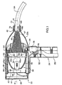
- a curing light "gun” for dental filling material is generally indicated by reference number 20 and includes a housing 22.
- the housing has a handle 24 which provides a “pistol” grip, and which incorporates a “trigger” switch 26.
- a flexible conduit 29 extends through and outwardly of the handle and encloses tubes 30 that are connected to an external water pump (not shown) and electrical cables 32 that are connected externally to a power supply (also not shown).
- Handle 24 allows the curing light to be held and manipulated by the dentist in use.
- Housing 22 includes a cylindrical body part 22a and a dome-shaped front part 22b that extends forwardly from the body part.
- a solid light guide 34 protrudes from the forward end of the housing.
- a light source 36 comprising a halogen bulb 38 and an elliptical reflector 40.
- Bulb 38 is a conventional halogen bulb and is mounted generally at the focal point of the reflector. The reflector is positioned to direct the light forwardly towards the light guide 34.
- Bulb 38 is plugged into a socket 39 which is supported by a removable retaining plate 42.
- Housing 22 has a removable end plate 44 for allowing access to the bulb.
- Bulb 38 and reflector 40 are disposed symmetrically with respect to a longitudinal axis A-A of housing 22.
- a sleeve 46 at the forward end of the housing receives the light guide and is also symmetrical about axis A-A so that the light guide 34 itself will be centered on that axis.
- the light guide has an input end 34a for receiving light from the light source, and an output end 34b for directing light to the target material to be cured.
- the curing gun includes non-imaging light concentrator means 47 between the light guide 34 and the light source 36, including a concentrator element 48 in the form of a solid of frusto-conical shape.
- the concentrator element is positioned symmetrically about axis A-A with its wide or base end 48a facing the light source 36 for receiving light from the source, and its narrower (output) end 48b remote from the light source and in "register" with the light guide 34.
- Light concentrator element 48 may be made of glass, or an appropriate plastic material such a polycarboriate, or polymethylmethacrylate.
- the light concentrator means 47 also includes a chamber 52 at the input end 48a of the concentrator element.
- Chamber 52 receives a liquid that is selected to cool the concentrator element and filter from the light passing from the light source to the concentrator element, light of a wavelength above a predetermined threshold, and to increase light collection from the source.
- chamber 52 is filled with water and forms a "water window”. Light above a wavelength of about 1300 nM is filtered by the water from the light that is transmitted to the concentrator element.
- chamber 52 is defined between a glass panel 54 that is held against an outer edge 40a of reflector 40 (at its point of largest diameter) and an annular extension 48c around the perimeter of the input end of concentrator element 48.
- An "O" ring seal 56 is provided between the glass panel 54 and the outer edge of extension 48c.
- the main body part 22a of housing 22 has a double wall for providing a water jacket around the light source 36.
- the inner wall is denoted 58 and the water jacket space is indicated at 60.
- Water is circulated through space 60 and through chamber 52 by way of tubes, two of which have previously been referred to and designated by reference numeral 30.
- the tubes are connected to chamber 52 by ports indicated at 62 and to the water jacket 60 by ports indicated at 64. While the precise direction of water flow is not believed critical, the water can, for example, flow first upwardly through chamber 52, then downwardly into the bottom of the water jacket, leaving through the top of the water jacket and flowing out via the conduit 29 to the external pump mentioned previously.
- Separate water flow circuits could of course be provided, as could a heat exchanger or reservoir for aiding dissipation of heat from the cooing water at a location remote from the curing gun itself.
- light rays from bulb 38 are directed by reflector 40 forwardly through chamber 52 where the "water window” removes heat and filters out light in the infrared range, i.e. above about 1300 nM.
- the light rays are refracted towards axis A-A in passing through the liquid, increasing light collection (as compared with a similar arrangement without the water window), are concentrated in concentrator element 48 and then delivered into the light guide 34.
- an interferential filter 66 of the type conventionally used in curing guns, but with a much narrower band of transmittance (460-490 nM).
- the filter is located at the inner end of the sleeve 46 on the front part 22b of housing 22 and is held in place by a tube 68 that is screw threaded into sleeve 46. This allows the filter to be replaced simply by removing tube 68.
- the light guide 34 is of course also replaceable. Normally, it will be “throw away” item that is discarded after each patient use.
- the inner end of the light guide is simply a sliding fit inside tube 68 and is held in place by "O" rings 70.
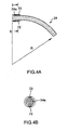
- Fig. 4 comprises views denoted a) and b) which show respectively a longitudinal sectional view and a transverse sectional view through a preferred form of light guide 34 for use in the curing gun of the invention. It is, however, to be understood that other forms of light guides can be used, including conventional guides.
- Light guide 34 originates as a straight cylindrical section 34a which is provided at its input end with two small flaps 72 for retention inside the tube 68 of the curing gun.
- the light guide then continues as a curved section 34b towards the output end of the light guide.
- the practically reasonable radius of curvature (R) of section 34(b) to minimize light losses and yet allow access to tooth surfaces inaccessible by a straight guide is determined by the index of refraction of the material from which the light guide is made and the diameter of the guide. Preferred ranges for the diameter of the light guide is 2-14 mm and for the radius of curvature (R) is 4-20 cm.
- the length of the straight section 34a may vary but the section extends at least to the outer ends of the flaps 72.
- suitable materials for the light guide are glass, polycarbonate, polymethylmethacrylate.
- the light guide can be made of other materials and in other sizes and curvatures or could be completely straight.
- a curing light in accordance with the invention allows the use of a bulb 38 of higher output than would otherwise be possible.
- This in turn allows the use of an interferential filter (filter 66) with a narrowly defined transmittance band (460-490 nM), which is at the peak of the light absorption capability of the camphorquinone material (470 nM) that is used as a photoactivator in light cured dental materials.
- filter 66 filters with a narrowly defined transmittance band
- 470 nM camphorquinone material
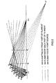
- Fig. 2 shows ray tracing for meridional rays emitted by a cylindrical bulb filament having a diameter of 3.5 mm and a length of 6 mm. Filaments of this type are used in 300-500 W halogen bulbs.
- the filament is shown situated at the first focal point of an elliptical reflector. The distance between two foci is 60 mm. The diameter of the reflector's outer edge is 42 mm.
- the solid lines represent rays emitted by a point source, placed at the focal point F1. These rays are projected by the reflector's elliptical surface (represented by points A, B, C, D, E, F, G) to the second focal point F2.
- the dashed lines and the chain-dotted lines represent rays emitted by the frontmost and rearmost points of the filament respectively. As is seen from the drawing, these rays arrive at points F' and F". Rays emitted by all other points of the filament surface are focused on the line joining F' and F". Therefore, there is no true focusing in this case.
- the beam's minimal radius (a perpendicular line joining F' with the optical axes at K) is about 15 mm. Therefore the light guide entrance should have a commensurate diameter i.e. 30 mm (which clearly is impractical in this application). A more reasonable size of guide will lead to inevitable power losses.
- a conventional light guide with an entrance diameter of 10 mm will decrease the light intensity up to 9 times, as compared with the ideal of 30 mm.
- the light beam diameter is decreased by the use of the non-imaging concentrator element 48; in the illustrated embodiment this is a solid transparent cone, employing the principle of total internal reflection.
- the second condition simply means that if, after a few reflections, the angle of incidence becomes lesser than the critical angle, light rays start to escape from the cone through side walls.
- Fig. 3 is a "developed" view of concentrator 48.
- the cone should be positioned in such a way that the most divergent ray AA' will strike the cone's wall at point P where the cone's diameter equals 21 mm (Fig. 3 - first condition -- see calculation for D in first condition). It is clear that some rays escape through the cone's walls or do not get into the "exit" aperture (48b).
- the performance of the concentrator will be adversely affected by overheating due to heat transfer from the light bulb. Without the "water window” 52 the cone will start to melt (or fracture in the case of glass) after 30 seconds of illumination.
- halogen light bulb reflectors have a multi-layer dichroic coating which reflects the blue part of the spectrum and transmits the red, only a few of them block reflection in the I.R. region (especially > 1200 nM). I.R. emission transferred by the light guide could cause unnecessary heating of tooth tissue.
- water is a very efficient I.R. filter.
- the thickness of the water layer preferably should be in a range of 5 - 21 mm.
- a 10 mm water layer is completely opaque for wavelengths higher than 1300 nM.
- Another useful feature of the water window 52 is that it provides the opportunity to use coloured water-soluble substances (e.g. CuSO 4 ) as an order separating filter in combination with a bandpass interferential filter. This can achieve a decrease in the heat load on the tooth without significant curing speed loss. Also the addition of various salts (example: CaCl 2 ) increases the refraction index of the window media and by this increases light collection.
- coloured water-soluble substances e.g. CuSO 4
- the loss due to reflection of light passing from air to glass is approximately 5% on each surface. Because of close values of refraction indices for water, glass and acrylic the relative refraction index for light passing from glass to water and from water to acrylic is very close to 1. Therefore the reflections on these boundaries are very low.
- a prototype curing gun as shown in Fig. 1 had a light output equal to 2,800 mW/cm 2 . This compares with an average power output of 500 - 600 mW/cm 2 for existing models.
- the prototype was equipped with a 9.5 degree cone having a diameter of 10 mm at the output end and 32 mm at the inner end, with a "water window” 8 mm thick and a 3 mm thick glass panel (54).
- the gun had an interferential filter with a band-pass of 100 nM (400-500 nM) and an acrylic light guide of a diameter of 10 mm and a curvature of 100 mm radius.
- the gun was fitted with a 340W bulb.
- Fig. 5 shows a concentrator of hollow truncated conical form. This form of concentrator will be transparent or with wall surfaces that are mirrored towards the interior. The concentrator can be liquid filled or used with a separate "water window”.
- Fig. 1 shows the interferential filter 66 to be located downstream of the concentrator element 48
- the interferential filter is positioned at the input end of the concentrator 48 between the concentrator element and the water window 52.
- the interferential filter is then directly cooled by the water, which may have some advantage in terms of avoiding heat damage to the filter.
- heat load on the concentrator element is then reduced because only the portions of the wavelengths of light that are passed by the interferential filter will then reach the concentrator element 48. In other words, the heat load on the concentrator element is reduced.
Landscapes
- Physics & Mathematics (AREA)
- Health & Medical Sciences (AREA)
- Optics & Photonics (AREA)
- General Physics & Mathematics (AREA)
- Veterinary Medicine (AREA)
- Animal Behavior & Ethology (AREA)
- General Health & Medical Sciences (AREA)
- Public Health (AREA)
- Life Sciences & Earth Sciences (AREA)
- Epidemiology (AREA)
- Dentistry (AREA)
- Oral & Maxillofacial Surgery (AREA)
- Dental Tools And Instruments Or Auxiliary Dental Instruments (AREA)
- Glass Compositions (AREA)
- Heating, Cooling, Or Curing Plastics Or The Like In General (AREA)
- Surface Treatment Of Glass Fibres Or Filaments (AREA)
Claims (6)
- Vorrichtung zum Härten von lichthärtbaren Materialien, die Folgendes umfasst:wobei der Lichtkonzentrator (47) eine Kammer (52) zur Aufnahme einer Flüssigkeit beinhaltet, die so gewählt wird, dass sie sowohl den Konzentrator kühlt als auch Licht mit einer Wellenlänge über einem vorbestimmten Schwellenwert aus dem von der Lichtquelle zum Konzentrator passierenden Licht filtert;eine Lichtquelle (38, 40);einen nicht bildgebenden Lichtkonzentrator (47) mit einem Eingangsende zum Empfangen von Licht von der Quelle und einem Ausgangsende, durch das ein konzentrierter Lichtstrahl den Konzentrator verlässt; undMittel (46, 48) am Ausgangsende des Lichtkonzentrators (47) zum Montieren eines Lichtleiters (34) mit einem Eingangsende zum Empfangen des genannten konzentrierten Lichtstrahls von dem Lichtkonzentrator (47) und einem Ausgangsende zum Richten von Licht auf ein zu härtendes Zielmaterial;
gekennzeichnet durch einen Interferenzfilter, der blaues Licht durchlässt und der am Eingangsende des Konzentrators (47) zwischen einem Konzentratorelement (48) und der Kammer (52) zum Kühlen durch die genannte Flüssigkeit angeordnet ist. - Vorrichtung nach Anspruch 1, bei der das Lichtkonzentratorelement (48) allgemein kegelstumpfförmig ist, über eine Längsachse verläuft und sich in Richtung auf das genannte Ausgangsende verjüngt, wobei das Element einen Halbkonuswinkel im Bereich von 7 bis 12 Grad hat und an seinem Eingangsende die genannte Kammer (52) zur Aufnahme der genannten Flüssigkeit aufweist, wobei die Kammer parallele Endflächen normal zu der genannten Achse und eine Dicke im Bereich von 5 bis 21 mm hat, so dass durch die Kammer strömendes Licht in Richtung auf die genannte Achse zum Konzentrieren des Lichtes gebeugt wird;
und wobei ein Körperteil eines Gehäuses der Vorrichtung einen Mantel (60) zum Kühlen von Flüssigkeit aufweist, wobei der genannte Mantel (60) um die Lichtquelle verläuft und mit der genannten Kammer (52) in Verbindung ist, damit Kühlflüssigkeit durch die Kammer (52) und den Mantel (60) zirkulieren kann. - Vorrichtung nach Anspruch 1, bei der die Lichtquelle (38) einen elliptischen Reflektor (40) und eine Glühbirne (38) am Brennpunkt des Reflektors (40) umfasst, wobei der Reflektor (40) eine Außenkante an einem maximalen Durchmesser des Reflektors hat und wobei die Kammer (52) eine Glasplatte (54) in Widerlagerbeziehung mit der genannten Außenkante des Reflektors (40) sowie einen ringförmigen Rand um den Umfang des Eingangsendes des Konzentratorelementes hat, der gegenüber der Glasplatte (54) abgedichtet ist, um die genannte Flüssigkeitsaufnahmekammer (52) zu definieren.
- Vorrichtung nach Anspruch 2 oder 3, bei der der genannte Kühlmantel (60) und die Kammer (52) über Kanäle (30) in Verbindung sind, die auch zur Außenseite des Gehäuses verlaufen, um es zuzulassen, dass die Kühlflüssigkeit von dem Gehäuse zum Abführen von Wärme zirkuliert wird, und um es zuzulassen, dass gekühltes Wasser durch den genannten Mantel (60) und die genannte Kammer (52) rezirkuliert wird.
- Vorrichtung nach Anspruch 1, 2, 3 oder 4 in Kombination mit einem Lichtleiter (34), der in den genannten Mitteln (46, 48) aufgenommen wird, um einen Lichtleiter zu empfangen, und umfassend einen massiven Stab, der als gerader zylindrischer Abschnitt beginnt und als gekrümmter Abschnitt in Richtung auf ein Ausgangsende des Lichtleiters fortfährt.
- Vorrichtung nach Anspruch 5, bei der der genannte Stab einen Durchmesser im Bereich von 2 bis 14 mm hat und der gekrümmte Abschnitt über einen Radius im Bereich von 4 bis 20 cm verläuft.
Applications Claiming Priority (3)
| Application Number | Priority Date | Filing Date | Title |
|---|---|---|---|
| US08/682,489 US5803729A (en) | 1996-07-17 | 1996-07-17 | Curing light |
| PCT/CA1997/000492 WO1998003132A1 (en) | 1996-07-17 | 1997-07-15 | Curing light |
| US682489 | 2001-09-07 |
Publications (2)
| Publication Number | Publication Date |
|---|---|
| EP0959803A1 EP0959803A1 (de) | 1999-12-01 |
| EP0959803B1 true EP0959803B1 (de) | 2003-05-21 |
Family
ID=24739933
Family Applications (1)
| Application Number | Title | Priority Date | Filing Date |
|---|---|---|---|
| EP97930269A Expired - Lifetime EP0959803B1 (de) | 1996-07-17 | 1997-07-15 | Lichthärtgerät |
Country Status (7)
| Country | Link |
|---|---|
| US (1) | US5803729A (de) |
| EP (1) | EP0959803B1 (de) |
| AT (1) | ATE240692T1 (de) |
| AU (1) | AU3430797A (de) |
| CA (1) | CA2276321C (de) |
| DE (1) | DE69722254T2 (de) |
| WO (1) | WO1998003132A1 (de) |
Cited By (7)
| Publication number | Priority date | Publication date | Assignee | Title |
|---|---|---|---|---|
| US7182597B2 (en) | 2002-08-08 | 2007-02-27 | Kerr Corporation | Curing light instrument |
| US7540634B2 (en) | 2004-06-15 | 2009-06-02 | Henkel Corporation | High power LED electro-optic assembly |
| US7989839B2 (en) | 2002-08-23 | 2011-08-02 | Koninklijke Philips Electronics, N.V. | Method and apparatus for using light emitting diodes |
| US8096691B2 (en) | 1997-09-25 | 2012-01-17 | Koninklijke Philips Electronics N V | Optical irradiation device |
| RU2472189C1 (ru) * | 2011-09-14 | 2013-01-10 | Федеральное государственное бюджетное учреждение науки Институт металлоорганической химии им. Г.А. Разуваева Российской академии наук (ИМХ РАН) | Применение фотополимеризующейся композиции для коннектирования световодов, способ коннектирования световодов и устройство для осуществления способа |
| US9066777B2 (en) | 2009-04-02 | 2015-06-30 | Kerr Corporation | Curing light device |
| US9726435B2 (en) | 2002-07-25 | 2017-08-08 | Jonathan S. Dahm | Method and apparatus for using light emitting diodes for curing |
Families Citing this family (113)
| Publication number | Priority date | Publication date | Assignee | Title |
|---|---|---|---|---|
| US6099520A (en) * | 1997-06-10 | 2000-08-08 | Shimoji; Yutaka | Method of using a cordless medical laser to cure composites and sterilize living tissue |
| US6200134B1 (en) | 1998-01-20 | 2001-03-13 | Kerr Corporation | Apparatus and method for curing materials with radiation |
| US6068474A (en) * | 1998-01-30 | 2000-05-30 | Ivoclar Ag | Light curing device |
| US6123545A (en) * | 1998-04-08 | 2000-09-26 | Ivoclar A.G. | Mains-operated device for curing by light a polymerizable dental material |
| US6439888B1 (en) * | 1999-05-03 | 2002-08-27 | Pls Liquidating Llc | Optical source and method |
| US6193510B1 (en) | 1999-07-28 | 2001-02-27 | Efraim Tsimerman | Medical device with time-out feature |
| US6345982B1 (en) | 1999-09-01 | 2002-02-12 | Darcy M. Dunaway | Dental light controller and concentrator |
| US6910886B2 (en) | 1999-09-24 | 2005-06-28 | Cao Group, Inc. | Curing light |
| US6974319B2 (en) * | 1999-09-24 | 2005-12-13 | Cao Group, Inc. | Curing light |
| US7294364B2 (en) * | 1999-09-24 | 2007-11-13 | Cao Group, Inc. | Method for curing composite materials |
| US7086858B2 (en) | 1999-09-24 | 2006-08-08 | Cao Group, Inc. | Semiconductor curing light system useful for curing light activated composite materials |
| US7077648B2 (en) * | 1999-09-24 | 2006-07-18 | Cao Group, Inc. | Curing light |
| US6755649B2 (en) | 1999-09-24 | 2004-06-29 | Cao Group, Inc. | Curing light |
| US6929472B2 (en) | 1999-09-24 | 2005-08-16 | Cao Group, Inc. | Curing light |
| US6971875B2 (en) * | 1999-09-24 | 2005-12-06 | Cao Group, Inc. | Dental curing light |
| US7066732B2 (en) * | 1999-09-24 | 2006-06-27 | Cao Group, Inc. | Method for curing light-curable materials |
| US6719559B2 (en) | 1999-09-24 | 2004-04-13 | Densen Cao | Curing light |
| US6932600B2 (en) * | 1999-09-24 | 2005-08-23 | Cao Group, Inc. | Curing light |
| US6780010B2 (en) | 1999-09-24 | 2004-08-24 | Cao Group, Inc. | Curing light |
| US6719558B2 (en) | 1999-09-24 | 2004-04-13 | Densen Cao | Curing light |
| US6981867B2 (en) | 1999-09-24 | 2006-01-03 | Cao Group, Inc. | Curing light |
| US6988891B2 (en) * | 1999-09-24 | 2006-01-24 | Cao Group, Inc. | Curing light |
| US6971876B2 (en) | 1999-09-24 | 2005-12-06 | Cao Group, Inc. | Curing light |
| US6953340B2 (en) * | 1999-09-24 | 2005-10-11 | Cao Group, Inc. | Light for use in activating light-activated materials, the light having a detachable light module containing a heat sink and a semiconductor chip |
| US6783362B2 (en) | 1999-09-24 | 2004-08-31 | Cao Group, Inc. | Dental curing light using primary and secondary heat sink combination |
| US6331111B1 (en) | 1999-09-24 | 2001-12-18 | Cao Group, Inc. | Curing light system useful for curing light activated composite materials |
| US7094054B2 (en) | 1999-09-24 | 2006-08-22 | Cao Group, Inc. | Dental curing light |
| US6988890B2 (en) | 1999-09-24 | 2006-01-24 | Cao Group, Inc. | Curing light |
| US6926524B2 (en) * | 1999-09-24 | 2005-08-09 | Cao Group, Inc. | Curing light |
| US6979193B2 (en) | 1999-09-24 | 2005-12-27 | Cao Group, Inc. | Curing light |
| WO2001056846A1 (en) * | 2000-02-04 | 2001-08-09 | Uegaki, Tateo | Repairing device for vehicles |
| US7049761B2 (en) | 2000-02-11 | 2006-05-23 | Altair Engineering, Inc. | Light tube and power supply circuit |
| US8093823B1 (en) | 2000-02-11 | 2012-01-10 | Altair Engineering, Inc. | Light sources incorporating light emitting diodes |
| US7320593B2 (en) | 2000-03-08 | 2008-01-22 | Tir Systems Ltd. | Light emitting diode light source for curing dental composites |
| US6520663B1 (en) | 2000-03-23 | 2003-02-18 | Henkel Loctite Corporation | UV curing lamp assembly |
| EP1138276A1 (de) | 2000-03-29 | 2001-10-04 | CMS-Dental ApS | Gerät zum Aushärten von Dentalwerkstoffen |
| US6638063B2 (en) * | 2000-05-02 | 2003-10-28 | Toei Electric Co., Ltd. | Optical apparatus and resin curing apparatus |
| CN1461205A (zh) * | 2000-08-04 | 2003-12-10 | 科尔公司 | 利用光辐射固化材料的设备和方法 |
| DE10040875C2 (de) * | 2000-08-18 | 2003-06-12 | 3M Espe Ag | Lichtsammeloptik mit einem kegelstumpfförmigen Element, diese enthaltendes Bestrahlungsgerät und deren bzw. dessen Verwendung |
| ATE463004T1 (de) * | 2000-11-06 | 2010-04-15 | Koninkl Philips Electronics Nv | Verfahren zur messung der bewegung eines eingabegeräts |
| WO2002071009A1 (en) * | 2001-03-01 | 2002-09-12 | Henkel Loctite Corporation | Integral filter support and shutter stop for uv curing system |
| US20040158300A1 (en) * | 2001-06-26 | 2004-08-12 | Allan Gardiner | Multiple wavelength illuminator having multiple clocked sources |
| WO2003002186A2 (en) * | 2001-06-26 | 2003-01-09 | Photomed Technologies, Inc. | Therapeutic methods using electromagnetic radiation |
| EP1409934B1 (de) * | 2001-07-23 | 2008-03-05 | Georg Ziemba | Verfahren zum gewinnen von kaltem licht aus sonneneinstrahlung, sowie solarkraftwerk |
| DE10138071A1 (de) * | 2001-08-03 | 2003-02-27 | Georg Knott | Bestrahlungsvorrichtung |
| US6692252B2 (en) | 2001-12-17 | 2004-02-17 | Ultradent Products, Inc. | Heat sink with geometric arrangement of LED surfaces |
| US7106523B2 (en) | 2002-01-11 | 2006-09-12 | Ultradent Products, Inc. | Optical lens used to focus led light |
| US6940659B2 (en) | 2002-01-11 | 2005-09-06 | Ultradent Products, Inc. | Cone-shaped lens having increased forward light intensity and kits incorporating such lenses |
| US6702576B2 (en) | 2002-02-22 | 2004-03-09 | Ultradent Products, Inc. | Light-curing device with detachably interconnecting light applicator |
| DE10222828B4 (de) * | 2002-05-21 | 2008-05-15 | 3M Espe Ag | Bestrahlungsgerät |
| FR2840414B1 (fr) * | 2002-06-04 | 2005-07-01 | Atmel Grenoble Sa | Composant de filtrage optique |
| EP1578295A4 (de) * | 2002-11-19 | 2008-02-20 | Dentaler lichtleiter | |
| US6890175B2 (en) | 2002-12-18 | 2005-05-10 | Ultradent Products, Inc. | Cooling system for hand-held curing light |
| US6994546B2 (en) | 2002-12-18 | 2006-02-07 | Ultradent Products, Inc. | Light curing device with detachable power supply |
| USD530013S1 (en) | 2003-02-18 | 2006-10-10 | Ultradent Products, Inc. | Dental illumination device |
| USD529613S1 (en) | 2003-02-18 | 2006-10-03 | Ultradent Products, Inc. | Dental illumination device |
| US7229201B2 (en) | 2003-03-26 | 2007-06-12 | Optim Inc. | Compact, high-efficiency, high-power solid state light source using a single solid state light-emitting device |
| US7798692B2 (en) * | 2003-03-26 | 2010-09-21 | Optim, Inc. | Illumination device |
| US20070020578A1 (en) * | 2005-07-19 | 2007-01-25 | Scott Robert R | Dental curing light having a short wavelength LED and a fluorescing lens for converting wavelength light to curing wavelengths and related method |
| US7192276B2 (en) | 2003-08-20 | 2007-03-20 | Ultradent Products, Inc. | Dental curing light adapted to emit light at a desired angle |
| US7144250B2 (en) | 2003-12-17 | 2006-12-05 | Ultradent Products, Inc. | Rechargeable dental curing light |
| US7195482B2 (en) | 2003-12-30 | 2007-03-27 | Ultradent Products, Inc. | Dental curing device having a heat sink for dissipating heat |
| US7074040B2 (en) | 2004-03-30 | 2006-07-11 | Ultradent Products, Inc. | Ball lens for use with a dental curing light |
| US7148498B1 (en) * | 2004-06-25 | 2006-12-12 | Henkel Corporation | Externally controlled electromagnetic energy spot curing system |
| US7056116B2 (en) | 2004-10-26 | 2006-06-06 | Ultradent Products, Inc. | Heat sink for dental curing light comprising a plurality of different materials |
| US8109981B2 (en) | 2005-01-25 | 2012-02-07 | Valam Corporation | Optical therapies and devices |
| US8113830B2 (en) | 2005-05-27 | 2012-02-14 | Kerr Corporation | Curing light instrument |
| US20070037114A1 (en) * | 2005-08-15 | 2007-02-15 | Shu-Lung Wang | Light directing apparatus for whitening |
| US8047686B2 (en) | 2006-09-01 | 2011-11-01 | Dahm Jonathan S | Multiple light-emitting element heat pipe assembly |
| US8118447B2 (en) | 2007-12-20 | 2012-02-21 | Altair Engineering, Inc. | LED lighting apparatus with swivel connection |
| US7712918B2 (en) | 2007-12-21 | 2010-05-11 | Altair Engineering , Inc. | Light distribution using a light emitting diode assembly |
| US8360599B2 (en) | 2008-05-23 | 2013-01-29 | Ilumisys, Inc. | Electric shock resistant L.E.D. based light |
| US7976196B2 (en) | 2008-07-09 | 2011-07-12 | Altair Engineering, Inc. | Method of forming LED-based light and resulting LED-based light |
| US7946729B2 (en) | 2008-07-31 | 2011-05-24 | Altair Engineering, Inc. | Fluorescent tube replacement having longitudinally oriented LEDs |
| US8674626B2 (en) | 2008-09-02 | 2014-03-18 | Ilumisys, Inc. | LED lamp failure alerting system |
| US8256924B2 (en) | 2008-09-15 | 2012-09-04 | Ilumisys, Inc. | LED-based light having rapidly oscillating LEDs |
| US8324817B2 (en) | 2008-10-24 | 2012-12-04 | Ilumisys, Inc. | Light and light sensor |
| US8214084B2 (en) | 2008-10-24 | 2012-07-03 | Ilumisys, Inc. | Integration of LED lighting with building controls |
| US8901823B2 (en) | 2008-10-24 | 2014-12-02 | Ilumisys, Inc. | Light and light sensor |
| US8653984B2 (en) | 2008-10-24 | 2014-02-18 | Ilumisys, Inc. | Integration of LED lighting control with emergency notification systems |
| US8444292B2 (en) | 2008-10-24 | 2013-05-21 | Ilumisys, Inc. | End cap substitute for LED-based tube replacement light |
| US7938562B2 (en) | 2008-10-24 | 2011-05-10 | Altair Engineering, Inc. | Lighting including integral communication apparatus |
| US8556452B2 (en) | 2009-01-15 | 2013-10-15 | Ilumisys, Inc. | LED lens |
| US8362710B2 (en) | 2009-01-21 | 2013-01-29 | Ilumisys, Inc. | Direct AC-to-DC converter for passive component minimization and universal operation of LED arrays |
| US8664880B2 (en) | 2009-01-21 | 2014-03-04 | Ilumisys, Inc. | Ballast/line detection circuit for fluorescent replacement lamps |
| US9072572B2 (en) | 2009-04-02 | 2015-07-07 | Kerr Corporation | Dental light device |
| US8330381B2 (en) | 2009-05-14 | 2012-12-11 | Ilumisys, Inc. | Electronic circuit for DC conversion of fluorescent lighting ballast |
| US8299695B2 (en) | 2009-06-02 | 2012-10-30 | Ilumisys, Inc. | Screw-in LED bulb comprising a base having outwardly projecting nodes |
| US8421366B2 (en) | 2009-06-23 | 2013-04-16 | Ilumisys, Inc. | Illumination device including LEDs and a switching power control system |
| US9057493B2 (en) | 2010-03-26 | 2015-06-16 | Ilumisys, Inc. | LED light tube with dual sided light distribution |
| WO2011119958A1 (en) | 2010-03-26 | 2011-09-29 | Altair Engineering, Inc. | Inside-out led bulb |
| CA2792940A1 (en) | 2010-03-26 | 2011-09-19 | Ilumisys, Inc. | Led light with thermoelectric generator |
| JP2011224042A (ja) * | 2010-04-15 | 2011-11-10 | Fujifilm Corp | 光源装置及びこれを用いた内視鏡装置 |
| US8454193B2 (en) | 2010-07-08 | 2013-06-04 | Ilumisys, Inc. | Independent modules for LED fluorescent light tube replacement |
| CA2803267A1 (en) | 2010-07-12 | 2012-01-19 | Ilumisys, Inc. | Circuit board mount for led light tube |
| WO2012058556A2 (en) | 2010-10-29 | 2012-05-03 | Altair Engineering, Inc. | Mechanisms for reducing risk of shock during installation of light tube |
| US8870415B2 (en) | 2010-12-09 | 2014-10-28 | Ilumisys, Inc. | LED fluorescent tube replacement light with reduced shock hazard |
| US9072171B2 (en) | 2011-08-24 | 2015-06-30 | Ilumisys, Inc. | Circuit board mount for LED light |
| EP2579075A1 (de) * | 2011-10-06 | 2013-04-10 | Ivoclar Vivadent AG | Stabförmiger Lichtleiter |
| US9500340B2 (en) | 2011-10-25 | 2016-11-22 | A-Dec, Inc. | Dental light using LEDs |
| ES2421408B1 (es) * | 2012-01-30 | 2014-12-18 | Daniel Enrique PEREZ RODRIGUEZ | Equipo de captación y distribución óptica, modular y adaptativo |
| WO2013131002A1 (en) | 2012-03-02 | 2013-09-06 | Ilumisys, Inc. | Electrical connector header for an led-based light |
| US9163794B2 (en) | 2012-07-06 | 2015-10-20 | Ilumisys, Inc. | Power supply assembly for LED-based light tube |
| US9271367B2 (en) | 2012-07-09 | 2016-02-23 | Ilumisys, Inc. | System and method for controlling operation of an LED-based light |
| US9285084B2 (en) | 2013-03-14 | 2016-03-15 | Ilumisys, Inc. | Diffusers for LED-based lights |
| US9267650B2 (en) | 2013-10-09 | 2016-02-23 | Ilumisys, Inc. | Lens for an LED-based light |
| WO2015112437A1 (en) | 2014-01-22 | 2015-07-30 | Ilumisys, Inc. | Led-based light with addressed leds |
| US9510400B2 (en) | 2014-05-13 | 2016-11-29 | Ilumisys, Inc. | User input systems for an LED-based light |
| US10159548B2 (en) | 2014-09-17 | 2018-12-25 | Garrison Dental Solutions, L.L.C. | Dental curing light |
| US10161568B2 (en) | 2015-06-01 | 2018-12-25 | Ilumisys, Inc. | LED-based light with canted outer walls |
| USD810293S1 (en) | 2017-01-20 | 2018-02-13 | Garrison Dental Solutions, Llc | Dental instrument |
| FR3089309A1 (fr) * | 2018-11-30 | 2020-06-05 | Commissariat A L'energie Atomique Et Aux Energies Alternatives | Coupleur optique |
| IT202100014150A1 (it) * | 2021-05-31 | 2022-12-01 | Vs Ortho Societa’ A Responsabilita’ Limitata | Lampada dentale foto-polimerizzante |
Family Cites Families (24)
| Publication number | Priority date | Publication date | Assignee | Title |
|---|---|---|---|---|
| US1550197A (en) * | 1923-06-06 | 1925-08-18 | Gen Electric | Radiation projector |
| US1590283A (en) * | 1924-10-20 | 1926-06-29 | De Forest B Catlin | Therapeutic device |
| US1677016A (en) * | 1926-07-01 | 1928-07-10 | Gen Electric | Quartz applicator |
| US2227422A (en) * | 1938-01-17 | 1941-01-07 | Edward W Boerstler | Applicator for use in treatment with therapeutic rays |
| US3596125A (en) | 1969-06-09 | 1971-07-27 | Wayne A Seigel | Liquid cooled radiation source with filter |
| US3712984A (en) * | 1971-03-15 | 1973-01-23 | Canrad Precision Ind Inc | Instrument for transmitting ultraviolet radiation to a limited area |
| AT355200B (de) | 1978-01-23 | 1980-02-25 | Espe Pharm Praep | Bestrahlungsgeraet zum aushaerten von durch strahlung haertbaren massen |
| DE2808045A1 (de) * | 1978-02-24 | 1979-09-06 | Nath Guenther | Bestrahlungsgeraet, insbesondere zur photopolymerisation von dentalkunststoffmassen |
| US4229658A (en) * | 1978-08-18 | 1980-10-21 | Dentsply Research & Development Corp. | Xenon light apparatus for supplying ultraviolet and visible spectra |
| DE7906381U1 (de) * | 1979-03-08 | 1979-07-12 | Richard Wolf Gmbh, 7134 Knittlingen | Beleuchtung fuer operations- und untersuchungsfelder |
| GB2070658B (en) | 1980-03-04 | 1984-02-29 | Boer Mueboer Es Cipoipari Kuta | Process for the production of chemically bonded non-woven sheet materials containing a binder of microheteroporous structure |
| US4836782A (en) | 1983-05-06 | 1989-06-06 | Dentsply Research & Development Corp. | Method for providing direct cool beam incident light on dental target |
| DE3424344A1 (de) * | 1984-07-03 | 1986-01-09 | Schuetz Dental Gmbh | Lichtbestrahlungsgeraet |
| US4729621A (en) * | 1985-03-11 | 1988-03-08 | Shiley Inc. | Integral optical fiber coupler |
| DE3523243C2 (de) * | 1985-06-28 | 2000-07-06 | Guenther Nath | Flüssigkeitslichtleiter zum Einsatz in einer Beleuchtungseinrichtung und Verwendung für medizinische Zwecke |
| DE3534342C1 (en) * | 1985-09-26 | 1987-03-12 | Kaltenbach & Voigt | Light transmitting dental hand-tool - for curing polymer based fillings |
| DE3611132A1 (de) | 1986-04-03 | 1987-10-08 | Espe Stiftung | Dentales bestrahlungsgeraet |
| CA2008515C (en) | 1990-01-24 | 1994-12-13 | Mohsen Kavenrad | Optical taper |
| US5184044A (en) * | 1990-08-13 | 1993-02-02 | Welch Allyn, Inc. | Dental curing lamp |
| US5147204A (en) | 1991-08-08 | 1992-09-15 | Minnesota Mining And Manufacturing Co. | Dental material curing apparatus |
| DE4211230C2 (de) | 1992-04-03 | 1997-06-26 | Ivoclar Ag | Wiederaufladbares Lichthärtgerät |
| EP0920840A3 (de) * | 1992-07-31 | 2000-03-29 | Molten Corporation | Kleines Lichtbestrahlungsgerät zum zahnärztlichen Gebrauch |
| CA2079698C (en) * | 1992-10-02 | 1999-08-10 | John Kennedy | An unbreakable disposable photocuring guide |
| US5290169A (en) * | 1992-11-02 | 1994-03-01 | Joshua Friedman | Optical light guide for dental light-curing lamps |
-
1996
- 1996-07-17 US US08/682,489 patent/US5803729A/en not_active Expired - Fee Related
-
1997
- 1997-07-15 WO PCT/CA1997/000492 patent/WO1998003132A1/en not_active Ceased
- 1997-07-15 AT AT97930269T patent/ATE240692T1/de not_active IP Right Cessation
- 1997-07-15 EP EP97930269A patent/EP0959803B1/de not_active Expired - Lifetime
- 1997-07-15 DE DE69722254T patent/DE69722254T2/de not_active Expired - Fee Related
- 1997-07-15 CA CA002276321A patent/CA2276321C/en not_active Expired - Fee Related
- 1997-07-15 AU AU34307/97A patent/AU3430797A/en not_active Abandoned
Cited By (7)
| Publication number | Priority date | Publication date | Assignee | Title |
|---|---|---|---|---|
| US8096691B2 (en) | 1997-09-25 | 2012-01-17 | Koninklijke Philips Electronics N V | Optical irradiation device |
| US9726435B2 (en) | 2002-07-25 | 2017-08-08 | Jonathan S. Dahm | Method and apparatus for using light emitting diodes for curing |
| US7182597B2 (en) | 2002-08-08 | 2007-02-27 | Kerr Corporation | Curing light instrument |
| US7989839B2 (en) | 2002-08-23 | 2011-08-02 | Koninklijke Philips Electronics, N.V. | Method and apparatus for using light emitting diodes |
| US7540634B2 (en) | 2004-06-15 | 2009-06-02 | Henkel Corporation | High power LED electro-optic assembly |
| US9066777B2 (en) | 2009-04-02 | 2015-06-30 | Kerr Corporation | Curing light device |
| RU2472189C1 (ru) * | 2011-09-14 | 2013-01-10 | Федеральное государственное бюджетное учреждение науки Институт металлоорганической химии им. Г.А. Разуваева Российской академии наук (ИМХ РАН) | Применение фотополимеризующейся композиции для коннектирования световодов, способ коннектирования световодов и устройство для осуществления способа |
Also Published As
| Publication number | Publication date |
|---|---|
| CA2276321C (en) | 2001-04-24 |
| HK1024847A1 (en) | 2000-10-27 |
| ATE240692T1 (de) | 2003-06-15 |
| DE69722254T2 (de) | 2003-11-27 |
| DE69722254D1 (de) | 2003-06-26 |
| AU3430797A (en) | 1998-02-10 |
| EP0959803A1 (de) | 1999-12-01 |
| WO1998003132A1 (en) | 1998-01-29 |
| US5803729A (en) | 1998-09-08 |
| CA2276321A1 (en) | 1998-01-29 |
Similar Documents
| Publication | Publication Date | Title |
|---|---|---|
| EP0959803B1 (de) | Lichthärtgerät | |
| US6102696A (en) | Apparatus for curing resin in dentistry | |
| JP5619689B2 (ja) | 光放射を用いて材料を硬化するための装置および方法 | |
| US5290169A (en) | Optical light guide for dental light-curing lamps | |
| US4948215A (en) | Dental light-curing lamp unit with interchangeable autofocus light guides | |
| US7106523B2 (en) | Optical lens used to focus led light | |
| US6554463B2 (en) | Optical waveguide concentrator and illuminating device | |
| US20030235800A1 (en) | LED curing light | |
| JP4393991B2 (ja) | 照射装置 | |
| US4836782A (en) | Method for providing direct cool beam incident light on dental target | |
| EP0920840A2 (de) | Kleines Lichtbestrahlungsgerät zum zahnärztlichen Gebrauch | |
| US5076660A (en) | Light source receptacle for fiberoptic illumination | |
| US20030215766A1 (en) | Light emitting systems and kits that include a light emitting device and one or more removable lenses | |
| US20050003322A1 (en) | Apparatus and method for curing materials with light radiation | |
| JPS5813214B2 (ja) | 輻射線によつて硬化させることのできる物質を照射するための装置 | |
| WO2004045445A1 (en) | Dental light guide | |
| JP2004065989A (ja) | 硬化用照光器具 | |
| WO1997036552A1 (en) | Apparatus and method for polymerising dental photopolymerisable compositions | |
| US6046460A (en) | Light curing device | |
| EP1138276A1 (de) | Gerät zum Aushärten von Dentalwerkstoffen | |
| HK1024847B (en) | Curing light | |
| US5658070A (en) | Method of varying luminous intensity of light in an illumination system | |
| CA2189498C (en) | Light curing device | |
| JP3091381B2 (ja) | 医療用照光ハンドピース | |
| CA2376608A1 (en) | Optical apparatus |
Legal Events
| Date | Code | Title | Description |
|---|---|---|---|
| PUAI | Public reference made under article 153(3) epc to a published international application that has entered the european phase |
Free format text: ORIGINAL CODE: 0009012 |
|
| 17P | Request for examination filed |
Effective date: 19990614 |
|
| AK | Designated contracting states |
Kind code of ref document: A1 Designated state(s): AT BE CH DE DK ES FI FR GB GR IE IT LI LU MC NL PT SE |
|
| 17Q | First examination report despatched |
Effective date: 20011113 |
|
| GRAG | Despatch of communication of intention to grant |
Free format text: ORIGINAL CODE: EPIDOS AGRA |
|
| GRAG | Despatch of communication of intention to grant |
Free format text: ORIGINAL CODE: EPIDOS AGRA |
|
| GRAG | Despatch of communication of intention to grant |
Free format text: ORIGINAL CODE: EPIDOS AGRA |
|
| GRAH | Despatch of communication of intention to grant a patent |
Free format text: ORIGINAL CODE: EPIDOS IGRA |
|
| GRAH | Despatch of communication of intention to grant a patent |
Free format text: ORIGINAL CODE: EPIDOS IGRA |
|
| GRAA | (expected) grant |
Free format text: ORIGINAL CODE: 0009210 |
|
| AK | Designated contracting states |
Designated state(s): AT BE CH DE DK ES FI FR GB GR IE IT LI LU MC NL PT SE |
|
| PG25 | Lapsed in a contracting state [announced via postgrant information from national office to epo] |
Ref country code: NL Free format text: LAPSE BECAUSE OF FAILURE TO SUBMIT A TRANSLATION OF THE DESCRIPTION OR TO PAY THE FEE WITHIN THE PRESCRIBED TIME-LIMIT Effective date: 20030521 Ref country code: FI Free format text: LAPSE BECAUSE OF FAILURE TO SUBMIT A TRANSLATION OF THE DESCRIPTION OR TO PAY THE FEE WITHIN THE PRESCRIBED TIME-LIMIT Effective date: 20030521 Ref country code: BE Free format text: LAPSE BECAUSE OF FAILURE TO SUBMIT A TRANSLATION OF THE DESCRIPTION OR TO PAY THE FEE WITHIN THE PRESCRIBED TIME-LIMIT Effective date: 20030521 Ref country code: AT Free format text: LAPSE BECAUSE OF FAILURE TO SUBMIT A TRANSLATION OF THE DESCRIPTION OR TO PAY THE FEE WITHIN THE PRESCRIBED TIME-LIMIT Effective date: 20030521 |
|
| REG | Reference to a national code |
Ref country code: GB Ref legal event code: FG4D |
|
| REG | Reference to a national code |
Ref country code: CH Ref legal event code: EP |
|
| REG | Reference to a national code |
Ref country code: IE Ref legal event code: FG4D |
|
| REF | Corresponds to: |
Ref document number: 69722254 Country of ref document: DE Date of ref document: 20030626 Kind code of ref document: P |
|
| PG25 | Lapsed in a contracting state [announced via postgrant information from national office to epo] |
Ref country code: LU Free format text: LAPSE BECAUSE OF NON-PAYMENT OF DUE FEES Effective date: 20030715 Ref country code: IE Free format text: LAPSE BECAUSE OF NON-PAYMENT OF DUE FEES Effective date: 20030715 |
|
| PG25 | Lapsed in a contracting state [announced via postgrant information from national office to epo] |
Ref country code: MC Free format text: LAPSE BECAUSE OF NON-PAYMENT OF DUE FEES Effective date: 20030731 |
|
| PG25 | Lapsed in a contracting state [announced via postgrant information from national office to epo] |
Ref country code: SE Free format text: LAPSE BECAUSE OF FAILURE TO SUBMIT A TRANSLATION OF THE DESCRIPTION OR TO PAY THE FEE WITHIN THE PRESCRIBED TIME-LIMIT Effective date: 20030821 Ref country code: PT Free format text: LAPSE BECAUSE OF FAILURE TO SUBMIT A TRANSLATION OF THE DESCRIPTION OR TO PAY THE FEE WITHIN THE PRESCRIBED TIME-LIMIT Effective date: 20030821 Ref country code: GR Free format text: LAPSE BECAUSE OF FAILURE TO SUBMIT A TRANSLATION OF THE DESCRIPTION OR TO PAY THE FEE WITHIN THE PRESCRIBED TIME-LIMIT Effective date: 20030821 Ref country code: DK Free format text: LAPSE BECAUSE OF FAILURE TO SUBMIT A TRANSLATION OF THE DESCRIPTION OR TO PAY THE FEE WITHIN THE PRESCRIBED TIME-LIMIT Effective date: 20030821 |
|
| PG25 | Lapsed in a contracting state [announced via postgrant information from national office to epo] |
Ref country code: ES Free format text: LAPSE BECAUSE OF FAILURE TO SUBMIT A TRANSLATION OF THE DESCRIPTION OR TO PAY THE FEE WITHIN THE PRESCRIBED TIME-LIMIT Effective date: 20030901 |
|
| REG | Reference to a national code |
Ref country code: CH Ref legal event code: NV Representative=s name: ISLER & PEDRAZZINI AG |
|
| NLV1 | Nl: lapsed or annulled due to failure to fulfill the requirements of art. 29p and 29m of the patents act | ||
| ET | Fr: translation filed | ||
| PLBE | No opposition filed within time limit |
Free format text: ORIGINAL CODE: 0009261 |
|
| STAA | Information on the status of an ep patent application or granted ep patent |
Free format text: STATUS: NO OPPOSITION FILED WITHIN TIME LIMIT |
|
| REG | Reference to a national code |
Ref country code: IE Ref legal event code: MM4A |
|
| 26N | No opposition filed |
Effective date: 20040224 |
|
| PG25 | Lapsed in a contracting state [announced via postgrant information from national office to epo] |
Ref country code: GB Free format text: LAPSE BECAUSE OF NON-PAYMENT OF DUE FEES Effective date: 20060715 |
|
| PGFP | Annual fee paid to national office [announced via postgrant information from national office to epo] |
Ref country code: IT Payment date: 20060731 Year of fee payment: 10 |
|
| PGFP | Annual fee paid to national office [announced via postgrant information from national office to epo] |
Ref country code: CH Payment date: 20070116 Year of fee payment: 10 |
|
| PGFP | Annual fee paid to national office [announced via postgrant information from national office to epo] |
Ref country code: DE Payment date: 20070130 Year of fee payment: 10 |
|
| GBPC | Gb: european patent ceased through non-payment of renewal fee |
Effective date: 20060715 |
|
| REG | Reference to a national code |
Ref country code: CH Ref legal event code: PCAR Free format text: ISLER & PEDRAZZINI AG;POSTFACH 1772;8027 ZUERICH (CH) |
|
| REG | Reference to a national code |
Ref country code: CH Ref legal event code: PL |
|
| PG25 | Lapsed in a contracting state [announced via postgrant information from national office to epo] |
Ref country code: LI Free format text: LAPSE BECAUSE OF NON-PAYMENT OF DUE FEES Effective date: 20070731 Ref country code: DE Free format text: LAPSE BECAUSE OF NON-PAYMENT OF DUE FEES Effective date: 20080201 Ref country code: CH Free format text: LAPSE BECAUSE OF NON-PAYMENT OF DUE FEES Effective date: 20070731 |
|
| PGFP | Annual fee paid to national office [announced via postgrant information from national office to epo] |
Ref country code: FR Payment date: 20070130 Year of fee payment: 10 |
|
| REG | Reference to a national code |
Ref country code: FR Ref legal event code: ST Effective date: 20080331 |
|
| PG25 | Lapsed in a contracting state [announced via postgrant information from national office to epo] |
Ref country code: FR Free format text: LAPSE BECAUSE OF NON-PAYMENT OF DUE FEES Effective date: 20070731 |
|
| PGFP | Annual fee paid to national office [announced via postgrant information from national office to epo] |
Ref country code: GB Payment date: 20060116 Year of fee payment: 9 |
|
| PG25 | Lapsed in a contracting state [announced via postgrant information from national office to epo] |
Ref country code: IT Free format text: LAPSE BECAUSE OF NON-PAYMENT OF DUE FEES Effective date: 20070715 |