EP0959720B1 - Systeme hydraulique de levage et d'abaissement pour une table de travail, un lit ou un meuble de repos ou un autre objet lourd - Google Patents
Systeme hydraulique de levage et d'abaissement pour une table de travail, un lit ou un meuble de repos ou un autre objet lourd Download PDFInfo
- Publication number
- EP0959720B1 EP0959720B1 EP97914169A EP97914169A EP0959720B1 EP 0959720 B1 EP0959720 B1 EP 0959720B1 EP 97914169 A EP97914169 A EP 97914169A EP 97914169 A EP97914169 A EP 97914169A EP 0959720 B1 EP0959720 B1 EP 0959720B1
- Authority
- EP
- European Patent Office
- Prior art keywords
- piston rod
- accumulator
- piston
- hydraulic
- cylinder
- Prior art date
- Legal status (The legal status is an assumption and is not a legal conclusion. Google has not performed a legal analysis and makes no representation as to the accuracy of the status listed.)
- Expired - Lifetime
Links
- 239000012530 fluid Substances 0.000 claims abstract description 33
- 238000007789 sealing Methods 0.000 claims abstract description 8
- 238000010276 construction Methods 0.000 claims abstract description 4
- 230000006835 compression Effects 0.000 claims description 10
- 238000007906 compression Methods 0.000 claims description 10
- 239000012528 membrane Substances 0.000 description 5
- 230000000740 bleeding effect Effects 0.000 description 4
- 238000005086 pumping Methods 0.000 description 2
- 239000007787 solid Substances 0.000 description 2
- 239000012190 activator Substances 0.000 description 1
- 230000005540 biological transmission Effects 0.000 description 1
- 238000009232 chiropractic Methods 0.000 description 1
- 230000000474 nursing effect Effects 0.000 description 1
- 238000000554 physical therapy Methods 0.000 description 1
- 230000001105 regulatory effect Effects 0.000 description 1
- 230000000284 resting effect Effects 0.000 description 1
Images

Classifications
-
- A—HUMAN NECESSITIES
- A47—FURNITURE; DOMESTIC ARTICLES OR APPLIANCES; COFFEE MILLS; SPICE MILLS; SUCTION CLEANERS IN GENERAL
- A47C—CHAIRS; SOFAS; BEDS
- A47C19/00—Bedsteads
- A47C19/04—Extensible bedsteads, e.g. with adjustment of length, width, height
- A47C19/045—Extensible bedsteads, e.g. with adjustment of length, width, height with entire frame height or inclination adjustments
-
- A—HUMAN NECESSITIES
- A47—FURNITURE; DOMESTIC ARTICLES OR APPLIANCES; COFFEE MILLS; SPICE MILLS; SUCTION CLEANERS IN GENERAL
- A47B—TABLES; DESKS; OFFICE FURNITURE; CABINETS; DRAWERS; GENERAL DETAILS OF FURNITURE
- A47B51/00—Cabinets with means for moving compartments up and down
-
- A—HUMAN NECESSITIES
- A47—FURNITURE; DOMESTIC ARTICLES OR APPLIANCES; COFFEE MILLS; SPICE MILLS; SUCTION CLEANERS IN GENERAL
- A47B—TABLES; DESKS; OFFICE FURNITURE; CABINETS; DRAWERS; GENERAL DETAILS OF FURNITURE
- A47B9/00—Tables with tops of variable height
- A47B9/02—Tables with tops of variable height with balancing device, e.g. by springs, by weight
-
- A—HUMAN NECESSITIES
- A47—FURNITURE; DOMESTIC ARTICLES OR APPLIANCES; COFFEE MILLS; SPICE MILLS; SUCTION CLEANERS IN GENERAL
- A47C—CHAIRS; SOFAS; BEDS
- A47C3/00—Chairs characterised by structural features; Chairs or stools with rotatable or vertically-adjustable seats
- A47C3/20—Chairs or stools with vertically-adjustable seats
- A47C3/30—Chairs or stools with vertically-adjustable seats with vertically-acting fluid cylinder
-
- B—PERFORMING OPERATIONS; TRANSPORTING
- B25—HAND TOOLS; PORTABLE POWER-DRIVEN TOOLS; MANIPULATORS
- B25H—WORKSHOP EQUIPMENT, e.g. FOR MARKING-OUT WORK; STORAGE MEANS FOR WORKSHOPS
- B25H1/00—Work benches; Portable stands or supports for positioning portable tools or work to be operated on thereby
- B25H1/14—Work benches; Portable stands or supports for positioning portable tools or work to be operated on thereby with provision for adjusting the bench top
- B25H1/16—Work benches; Portable stands or supports for positioning portable tools or work to be operated on thereby with provision for adjusting the bench top in height
Definitions
- the invention relates to a hydraulic lifting-lowering-system for a working table, a couch or lying furniture or another heavy object, the height level of which it is frequently desired to adjust or change, and said system comprising a predetermined amount of hydraulic fluid, a hydraulic fluid accumulator, the fluid pressure of which on the hydraulic fluid side is adjustable, a single acting hydraulic cylinder with two end caps, a piston pressure chamber and a piston rod which via a piston rod sealing ring extends sealingly out through the one end cap of the cylinder.
- a hydraulic system according to claim 1 which is special by the combination that the hydraulic cylinder is of the plunger piston type and that the piston rod is extending sealingly via a piston rod sealing ring out through the one end cap of the cylinder.
- the end caps of the hydraulic cylinder are connected via an inner telescopic tube carried telescopically in the cylindric guiding tube serving as an outer telescopic tube, which together with the plunger piston rod has been secured coaxially in a mounting block, and the outer telescopic tube via a slide bushing externally upon the inner telescopic tube at that end cap, through which the piston rod extends, together with a slide bushing in the outer end of the outer telescopic tube is adapted to guide the inner telescopic tube when it is displaced in the outer telescopic tube.
- An advantage connected thereto is that even though the operating pressure is rather high, typically 40-150 bar, a rugged and stable guiding can be achieved at low friction of the telescopic construction.
- the plunger piston rod advantageously may comprise a longitudinal bore forming a part of the pressure fluid connection between the piston pressure chamber and the hydraulic fluid side of the accumulator.
- the hydraulic fluid accumulator may e.g. be of the kind with a pressure fluid tight membrane separating the hydraulic fluid from a gaseous fluid serving as pneumatic spring. This permits the system to obtain very low friction losses in the accumulator and thus permits low manoeuvering forces for a user who desires to change said height adjustment. A possible adjustability of the gas pressure permits a change of the force of the supporting ability of the hydraulic cylinder.
- the accumulator may also be of the spring type whereby a compression spring exerts a force on a piston in an accumulator cylinder.
- a compression spring exerts a force on a piston in an accumulator cylinder.
- An embodiment, by which the hydraulic fluid accumulator is of the spring type, and a compression spring exerts a force against a piston in an accumulator cylinder, is characterized in that the wall of the accumulator cylinder is formed by that part off the plunger cylinder wall which is situated between a stop ring and one end cap, whereby the piston is arranged also in the hydraulic cylinder and is fluid proof sealed and displaceable on the plunger piston rod between said stop ring on said piston rod and said end cap into which the piston rod is displaceably arranged.
- the spring is thus fully built-in in the hydraulic cylinder, whereby a small outer diameter for the lifting-lowering-unit can be achieved at the expense of the fact that the spring should be dimensioned with the free length and spring characteristic demanded for the relevant and thus economical lifting-lowering-unit.
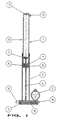
- Fig. 1 shows an inner telescopic tube 1, formed as a cylinder wall 1 in a hydraulic plunger cylinder 1, 6, 7, 10, 11, 12 and 17, said inner telescopic tube 1 being arranged in an outer telescopic tube 2 which in turn is secured in a mounting block 3.
- a pressure accumulator 5 of the membrane type which in the embodiment shown is a gas pressure accumulator which against its membrane has a predetermined but possibly adjustable nitrogene pressure corresponding to the highest working pressure in the piston pressure chamber 17 of the cylinder.
- the plunger piston rod 6 in the plunger cylinder is in the embodiment shown provided with a stop ring 7 at its one end and is at its other end fastened coaxially in the mounting block 3.
- slide bushings 8 On the outer end of the outer telescopic tube 2 and on the inner end of the inner telescopic tube 1 is arranged slide bushings 8 so that the outer tube 2 may guide the inner tube 1.
- the one end piece or cap 10 of the cylinder 1 with piston rod washer or sealing 11 and other end piece or cap 12 with bleeder valve 13 is connected via the inner telescopic tube 1.
- an air filter 14 for permitting the air from the inner of the tube 2 to escape or to be sucked in during the stroke of the plunger piston.
- a filling means 16 for hydraulic fluid under a predetermined pressure and possibly a quantity regulation valve 15 for adjustment of the flow rate between the accumulator 5 and the piston pressure chamber 17.
- the plunger cylinder is formed by the inner tube 1, the plunger piston rod 6, the stop ring 7, the end caps 10 and 12 and the piston pressure chamber 17.
- the piston pressure chamber 17 is enclosed by the inner tube 1 and of the end pieces 10 and 12 and is connected to the accumulator 5 with respect to the flow by a tube system, here formed by a longitudinal bore 18 in the piston rod 6 and a connection channel in the mounting block.
- the stop ring 7 may also be used as guide ring by providing it externally with a slide bushing not shown, which is adapted to slide on the inner wall of the inner tube 1.
- the stop ring 7 should be provided with axial flow openings or the channel 18 should have discharge openings to both sides of the stop ring 7 so that the pressure fluid is free to fill the chamber 17.
- the working table is ready for use when a load, e.g. a working table with tools or other equipment, is supported by the unit shown in Fig. 1 resting on its mounting block 3 and being under a fluid pressure corresponding to the vertical load on the unit, where the pressure in the chamber 17 against the cross sectional area of the plunger piston rod, provides the unit with enough force to support the load.
- a load e.g. a working table with tools or other equipment
- the table may with a relatively small manual pulling or pushing force be moved upwards or downwards to a new working height without the trouble hitherto being connected to such constructions, which implied pumping operations, start and stop of electromotors or manual rotation of crank handles in order to change the working height of the table.
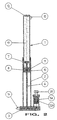
- Fig. 2 the hydraulic gas pressure accumulator has been replaced by a compression spring influenced hydraulic piston accumulator 5A which easily by means of an adjustment screw 20 may have amended the spring pressure of the compression spring 22A and thus the fluid pressure in the unit.
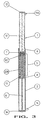
- Fig. 3 appears another unit with a hydraulic piston accumulator, the piston 10C forming an end cap for the piston pressure chamber 17, said cap being spring loaded by the accumulator spring 22B.
- the piston 10C is mounted slidably and as well sealed by sealings against the plunger piston rod 6A which is solid, as well as against the inner telescopic tube 1.
- This spring 22B of the piston accumulator is performed with a fixed free length and a certain spring characteristic which is adapted to the load and the height position range to which the unit of Fig. 3 should be exposed. The economy will be good by high piece numbers, but at the expense of adjustability of the unit.
- Figs. 4-6 an accumulator arranged coaxially to the plunger cylinder in stead of the accumulator shown in Fig. 2.
- the spring 22C of said accumulator is so arranged outside and around the outer tube 2 that the pressure range can be adjusted by screwing a threaded bushing 23 to tightening or slackening of the spring 22C by means of a control lever 25.
- Fig. 4-6 an accumulator arranged coaxially to the plunger cylinder in stead of the accumulator shown in Fig. 2.
- the spring 22C of said accumulator is so arranged outside and around the outer tube 2 that the pressure range can be adjusted by screwing a threaded bushing 23 to tightening or slackening of the spring 22C by means of a control lever 25.
- FIG. 4 shows a seeger circlip 27 for limitation of the setting range or setting movement, an upper supporting plate 26, a mechanical lock 28, an air bleeding and hydraulic fluid filling means 9A, three air bleeding holes 29, a stationary O-ring 30 and a dynamic sealing 31 in the end cap 10, a sliding sleeve or band 32, a dynamic sealing 33, a pressure regulating screw 34, an accumulating chamber 35 and a spring travel chamber 36, the air bleeding hole of which - along with the other air bleeding holes 29 - may be provided with an air filter.
Landscapes
- Engineering & Computer Science (AREA)
- Mechanical Engineering (AREA)
- Actuator (AREA)
- Forklifts And Lifting Vehicles (AREA)
- Chairs Characterized By Structure (AREA)
- Tables And Desks Characterized By Structural Shape (AREA)
Claims (4)
- Système hydraulique pour le levage et l'abaissement d'une table de travail, d'une couchette ou d'un meuble de repos ou tout autre objet lourd, dont on désire fréquemment ajuster ou modifier le niveau ou la position en hauteur, ce système comportant une quantité prédéterminée d'un fluide hydraulique, un accumulateur de fluide hydraulique (5) dont la pression fluidique sur le côté fluide hydraulique est ajustable, un cylindre hydraulique d'actionnement unique (1, 6, 7, 10, 11, 12, 17) comportant deux calottes terminales (10, 12), une chambre sous pression pour le piston (17) et une tige de piston (6), dans lequel la chambre de pression du piston (17) est connectée par pression fluidique au côté fluide hydraulique de l'accumulateur (5), la paroi du cylindre hydraulique étant coulissante et montée télescopiquement dans un tube de guidage cylindrique (2) entourant la tige de piston sur la totalité de sa longueur et fixée rigidement à une extrémité de la tige de piston par l'intermédiaire d'une plaque transversale (3A) ou un élément constructif semblable, caractérisé par la combinaison selon laquelle le cylindre hydraulique (1, 6, 7, 10, 11, 12, 17) est du type à piston plongeur, la tige de piston (6) se prolongeant hermétiquement par une bague d'étanchéisation de la tige de piston (11) à travers la calotte terminale (10) du cylindre.
- Système selon la revendication 1, caractérisé en ce que les calottes terminales (10, 12) du cylindre hydraulique (1, 6, 7, 10, 11, 12, 17) sont connectées par l'intermédiaire d'un cube télescopique inteme (1) qui est supporté télescopiquement dans le tube de guidage cylindrique (2) servant de tube télescopique externe, qui, en combinaison avec la tige du piston plongeur (6), est fixée coaxialement dans un bloc de montage (3) et en ce que le tube télescopique extérieur (2) s'étend par l'intermédiaire d'une garniture coulissante (8) extérieure au tube télescopique intérieur (11) à l'emplacement de la calotte terminale (10) que traverse la tige de piston, en même temps qu'une garniture coulissante (8) dans l'extrémité extérieure du tube télescopique extérieur (2) est destinée à guider le tube télescopique intérieur (1) quand il est déplacé à l'intérieur du tube télescopique extérieur (2).
- Système selon la revendication 1 ou 2, caractérisé en ce que la tige du piston plongeur (6) présente un alésage longitudinal (18) constituant un élément de la connexion fluidique sous pression entre la chambre sous pression du piston (17) et le côté fluide hydraulique de l'accumulateur (5).
- Système selon la revendication 1 ou 2, dans lequel l'accumulateur de fluide hydraulique est du type à ressort,et un ressort de compression (22B) exerce une force à l'encontre d'un piston (10C) dans un cylindre accumulateur (5), caractérisé en ce que la paroi du cylindre de l'accumulateur (5) est constituée par la partie de la paroi du cylindre plongeur (1) qui est située entre une bague d'arrêt (7) et une calotte terminale (10), le piston (10C) étant également disposé dans le cylindre hydraulique (1, 6, 7, 10, 11, 12, 17), et étant hermétiquement étanche au fluide et déplaçable sur la tige du piston plongeur (6) entre ladite bague d'arrêt (7) sur la tige de piston (6) et ladite calotte terminale (10) dans laquelle la tige de piston (6) est disposée de manière déplaçable.
Applications Claiming Priority (3)
| Application Number | Priority Date | Filing Date | Title |
|---|---|---|---|
| DK30096 | 1996-03-15 | ||
| DK030096A DK172403B1 (da) | 1996-03-15 | 1996-03-15 | Hydraulisk aktuatorkredsløb til et hæve-sænke-system for et arbejdsbord, et liggemøbel eller en anden tung genstand |
| PCT/DK1997/000117 WO1997034513A1 (fr) | 1996-03-15 | 1997-03-17 | Systeme hydraulique de levage et d'abaissement pour une table de travail, un lit ou un meuble de repos ou un autre objet lourd |
Publications (2)
| Publication Number | Publication Date |
|---|---|
| EP0959720A1 EP0959720A1 (fr) | 1999-12-01 |
| EP0959720B1 true EP0959720B1 (fr) | 2003-02-12 |
Family
ID=8091997
Family Applications (1)
| Application Number | Title | Priority Date | Filing Date |
|---|---|---|---|
| EP97914169A Expired - Lifetime EP0959720B1 (fr) | 1996-03-15 | 1997-03-17 | Systeme hydraulique de levage et d'abaissement pour une table de travail, un lit ou un meuble de repos ou un autre objet lourd |
Country Status (8)
| Country | Link |
|---|---|
| US (1) | US6272853B1 (fr) |
| EP (1) | EP0959720B1 (fr) |
| AT (1) | ATE232366T1 (fr) |
| AU (1) | AU2152197A (fr) |
| DE (1) | DE69719081T2 (fr) |
| DK (1) | DK172403B1 (fr) |
| ES (1) | ES2192673T3 (fr) |
| WO (1) | WO1997034513A1 (fr) |
Cited By (1)
| Publication number | Priority date | Publication date | Assignee | Title |
|---|---|---|---|---|
| CN107461587A (zh) * | 2017-07-25 | 2017-12-12 | 合肥红铭网络科技有限公司 | 一种个人计算机显示屏支撑结构 |
Families Citing this family (15)
| Publication number | Priority date | Publication date | Assignee | Title |
|---|---|---|---|---|
| GB0204861D0 (en) * | 2002-03-01 | 2002-04-17 | Maciever Ian | Access platform |
| US6817827B2 (en) | 2003-01-23 | 2004-11-16 | Frank Targonski | Lifting apparatus with stabilizer |
| AU2008100972B4 (en) * | 2004-08-16 | 2009-01-22 | Flat Pty Ltd | A support for supporting a structure on a surface |
| WO2006017891A1 (fr) | 2004-08-16 | 2006-02-23 | Flat Pty Ltd | Support pour tenir une structure sur une surface |
| TWI439709B (zh) * | 2006-12-29 | 2014-06-01 | Intest Corp | 用於使負載沿平移軸線平移之操縱器與負載定位系統 |
| CN101848692A (zh) * | 2007-09-20 | 2010-09-29 | 姿势校正工具公司 | 改进型整脊姿势矫正工具 |
| DE102008010249B4 (de) * | 2008-02-20 | 2022-08-25 | Stabilus Gmbh | Antriebseinrichtung |
| US20120153245A1 (en) * | 2010-12-20 | 2012-06-21 | Zloch David A | Furniture lifting device |
| US9612415B2 (en) | 2013-10-14 | 2017-04-04 | Hubbell Incorporated | Swing arm assemblies for utility vaults |
| CN105033971A (zh) * | 2015-08-04 | 2015-11-11 | 天威保变(合肥)变压器有限公司 | 线圈除漆放置架 |
| MX2017009908A (es) * | 2015-12-17 | 2018-06-20 | Flat Pty Ltd | Soporte hidraulico. |
| CN208114761U (zh) * | 2016-11-11 | 2018-11-20 | 通快医疗系统两合公司 | 用于手术台的密封装置 |
| CN110307291B (zh) * | 2019-06-28 | 2021-05-04 | 枞阳县白云生态园林有限责任公司 | 一种具有导向和防护双重功能的农业机械用支撑结构 |
| US20220322839A1 (en) * | 2021-04-08 | 2022-10-13 | Slope Sleep, LLC | Bed Inclining System |
| CN114618831B (zh) * | 2021-12-23 | 2023-04-11 | 山东科技职业学院 | 一种除雪杆 |
Family Cites Families (11)
| Publication number | Priority date | Publication date | Assignee | Title |
|---|---|---|---|---|
| US3168278A (en) * | 1962-05-02 | 1965-02-02 | Ralph P Ogden | Hydro-mechanical vehicle seat suspension |
| FR1490706A (fr) * | 1966-06-23 | 1967-08-04 | Fernand Couvreur S P R L Ets | Table à dessin |
| US3436048A (en) * | 1967-06-05 | 1969-04-01 | Greer Hydraulics Inc | Seat assembly for vehicles |
| US3486417A (en) * | 1968-03-04 | 1969-12-30 | Int Harvester Co | Seat suspension assembly |
| DE2164943C3 (de) * | 1971-12-28 | 1981-03-19 | Fritz Bauer + Söhne oHG, 8503 Altdorf | Hydraulisch blockierbare Hubvorrichtung |
| JPS5016247A (fr) * | 1973-06-18 | 1975-02-20 | ||
| US3865341A (en) * | 1973-08-08 | 1975-02-11 | Den Tal Ez Mfg Co | Dental stool for dentist and dental assistant |
| DE2528980C2 (de) * | 1975-06-28 | 1984-04-05 | Stabilus Gmbh, 5400 Koblenz | Blockierbares Hubaggregat mit Zusatzfeder |
| US4373334A (en) * | 1979-09-26 | 1983-02-15 | Carlander Lars Erik | Device for variable height adjustment of supports |
| GB2095364B (en) * | 1981-03-24 | 1985-07-24 | Wipac Group Sales | Adjustable fluid support devices for swivel chairs |
| SE446499B (sv) * | 1984-03-16 | 1986-09-22 | Lars Johansson | Anordning vid ett bord som innefattar en hoj- och senkbar bordsskiva |
-
1996
- 1996-03-15 DK DK030096A patent/DK172403B1/da not_active IP Right Cessation
- 1996-03-17 US US09/142,827 patent/US6272853B1/en not_active Expired - Fee Related
-
1997
- 1997-03-17 AU AU21521/97A patent/AU2152197A/en not_active Abandoned
- 1997-03-17 ES ES97914169T patent/ES2192673T3/es not_active Expired - Lifetime
- 1997-03-17 AT AT97914169T patent/ATE232366T1/de not_active IP Right Cessation
- 1997-03-17 EP EP97914169A patent/EP0959720B1/fr not_active Expired - Lifetime
- 1997-03-17 DE DE69719081T patent/DE69719081T2/de not_active Expired - Fee Related
- 1997-03-17 WO PCT/DK1997/000117 patent/WO1997034513A1/fr not_active Ceased
Cited By (1)
| Publication number | Priority date | Publication date | Assignee | Title |
|---|---|---|---|---|
| CN107461587A (zh) * | 2017-07-25 | 2017-12-12 | 合肥红铭网络科技有限公司 | 一种个人计算机显示屏支撑结构 |
Also Published As
| Publication number | Publication date |
|---|---|
| DE69719081D1 (de) | 2003-03-20 |
| ES2192673T3 (es) | 2003-10-16 |
| WO1997034513A1 (fr) | 1997-09-25 |
| AU2152197A (en) | 1997-10-10 |
| US6272853B1 (en) | 2001-08-14 |
| ATE232366T1 (de) | 2003-02-15 |
| DK172403B1 (da) | 1998-05-18 |
| DE69719081T2 (de) | 2003-12-11 |
| EP0959720A1 (fr) | 1999-12-01 |
| DK30096A (da) | 1997-09-16 |
Similar Documents
| Publication | Publication Date | Title |
|---|---|---|
| EP0959720B1 (fr) | Systeme hydraulique de levage et d'abaissement pour une table de travail, un lit ou un meuble de repos ou un autre objet lourd | |
| US4004836A (en) | Chair with tiltable spring biased back-rest | |
| EP0423828B1 (fr) | Dispositif de réglage | |
| US5447149A (en) | Adjustable position fixing apparatus for instrument and the like | |
| JPS60211138A (ja) | ばね力調節可能なガスばね | |
| US4830432A (en) | Positioning device | |
| EP0026526B1 (fr) | Dispositif pour l'ajustement en hauteur de supports | |
| EP1778946A1 (fr) | Support pour tenir une structure sur une surface | |
| SI1308594T1 (en) | Damping device for movable furniture parts | |
| US4800668A (en) | Adjustable tension fishing rod | |
| CA2248983C (fr) | Systeme hydraulique de levage et d'abaissement pour une table de travail, un lit ou un meuble de repos ou un autre objet lourd | |
| US20130223919A1 (en) | Connection device for adjustable connection of medical equipment to a stationary fixture | |
| WO1993004739A1 (fr) | Appareil de musculation utilisant la resistance d'un fluid | |
| US7673941B2 (en) | Delayed gas spring chair | |
| KR101588821B1 (ko) | 의료용 작업 테이블 암 | |
| US2819132A (en) | Chiropractic table with adjustable auxiliary table section | |
| WO1986000796A1 (fr) | Bequille, canne et analogues de longueur variable en continu | |
| KR100456220B1 (ko) | 의자 개스스프링 | |
| EP0414717B1 (fr) | Agencement de reduction d'une charge | |
| FR2287191A1 (fr) | Colonne reglable en hauteur, en particulier pour sieges | |
| KR0139076Y1 (ko) | 단전호흡운동구용 유압실린더 | |
| MX9605605A (es) | Mecanismo de ajuste de altura, hidraulico, para silla. | |
| WO1990012220A1 (fr) | Dipositif hydraulique pour chaises | |
| KR930008472B1 (ko) | 의자의 높이조절 장치 | |
| GB2033811A (en) | Swaging press |
Legal Events
| Date | Code | Title | Description |
|---|---|---|---|
| PUAI | Public reference made under article 153(3) epc to a published international application that has entered the european phase |
Free format text: ORIGINAL CODE: 0009012 |
|
| 17P | Request for examination filed |
Effective date: 19981002 |
|
| AK | Designated contracting states |
Kind code of ref document: A1 Designated state(s): AT BE CH DE ES FI FR GB IT LI NL SE |
|
| GRAG | Despatch of communication of intention to grant |
Free format text: ORIGINAL CODE: EPIDOS AGRA |
|
| 17Q | First examination report despatched |
Effective date: 20020409 |
|
| GRAG | Despatch of communication of intention to grant |
Free format text: ORIGINAL CODE: EPIDOS AGRA |
|
| GRAH | Despatch of communication of intention to grant a patent |
Free format text: ORIGINAL CODE: EPIDOS IGRA |
|
| GRAH | Despatch of communication of intention to grant a patent |
Free format text: ORIGINAL CODE: EPIDOS IGRA |
|
| GRAA | (expected) grant |
Free format text: ORIGINAL CODE: 0009210 |
|
| AK | Designated contracting states |
Designated state(s): AT BE CH DE ES FI FR GB IT LI NL SE |
|
| PG25 | Lapsed in a contracting state [announced via postgrant information from national office to epo] |
Ref country code: BE Free format text: LAPSE BECAUSE OF FAILURE TO SUBMIT A TRANSLATION OF THE DESCRIPTION OR TO PAY THE FEE WITHIN THE PRESCRIBED TIME-LIMIT Effective date: 20030212 |
|
| REG | Reference to a national code |
Ref country code: GB Ref legal event code: FG4D |
|
| REG | Reference to a national code |
Ref country code: CH Ref legal event code: EP |
|
| REF | Corresponds to: |
Ref document number: 69719081 Country of ref document: DE Date of ref document: 20030320 Kind code of ref document: P |
|
| REG | Reference to a national code |
Ref country code: SE Ref legal event code: TRGR |
|
| REG | Reference to a national code |
Ref country code: CH Ref legal event code: NV Representative=s name: ABREMA AGENCE BREVETS ET MARQUES GANGUILLET & HUMP |
|
| REG | Reference to a national code |
Ref country code: ES Ref legal event code: FG2A Ref document number: 2192673 Country of ref document: ES Kind code of ref document: T3 |
|
| ET | Fr: translation filed | ||
| PLBE | No opposition filed within time limit |
Free format text: ORIGINAL CODE: 0009261 |
|
| STAA | Information on the status of an ep patent application or granted ep patent |
Free format text: STATUS: NO OPPOSITION FILED WITHIN TIME LIMIT |
|
| PGFP | Annual fee paid to national office [announced via postgrant information from national office to epo] |
Ref country code: AT Payment date: 20040108 Year of fee payment: 8 |
|
| 26N | No opposition filed |
Effective date: 20031113 |
|
| PGFP | Annual fee paid to national office [announced via postgrant information from national office to epo] |
Ref country code: CH Payment date: 20040330 Year of fee payment: 8 |
|
| PGFP | Annual fee paid to national office [announced via postgrant information from national office to epo] |
Ref country code: FI Payment date: 20050311 Year of fee payment: 9 |
|
| PG25 | Lapsed in a contracting state [announced via postgrant information from national office to epo] |
Ref country code: AT Free format text: LAPSE BECAUSE OF NON-PAYMENT OF DUE FEES Effective date: 20050317 |
|
| PG25 | Lapsed in a contracting state [announced via postgrant information from national office to epo] |
Ref country code: LI Free format text: LAPSE BECAUSE OF NON-PAYMENT OF DUE FEES Effective date: 20050331 Ref country code: CH Free format text: LAPSE BECAUSE OF NON-PAYMENT OF DUE FEES Effective date: 20050331 |
|
| PGFP | Annual fee paid to national office [announced via postgrant information from national office to epo] |
Ref country code: ES Payment date: 20050331 Year of fee payment: 9 |
|
| REG | Reference to a national code |
Ref country code: CH Ref legal event code: PL |
|
| PGFP | Annual fee paid to national office [announced via postgrant information from national office to epo] |
Ref country code: NL Payment date: 20060316 Year of fee payment: 10 |
|
| PG25 | Lapsed in a contracting state [announced via postgrant information from national office to epo] |
Ref country code: FI Free format text: LAPSE BECAUSE OF NON-PAYMENT OF DUE FEES Effective date: 20060317 |
|
| PG25 | Lapsed in a contracting state [announced via postgrant information from national office to epo] |
Ref country code: ES Free format text: LAPSE BECAUSE OF NON-PAYMENT OF DUE FEES Effective date: 20060318 |
|
| PGFP | Annual fee paid to national office [announced via postgrant information from national office to epo] |
Ref country code: FR Payment date: 20060328 Year of fee payment: 10 |
|
| PGFP | Annual fee paid to national office [announced via postgrant information from national office to epo] |
Ref country code: DE Payment date: 20060329 Year of fee payment: 10 |
|
| PGFP | Annual fee paid to national office [announced via postgrant information from national office to epo] |
Ref country code: IT Payment date: 20060331 Year of fee payment: 10 |
|
| PG25 | Lapsed in a contracting state [announced via postgrant information from national office to epo] |
Ref country code: SE Free format text: LAPSE BECAUSE OF NON-PAYMENT OF DUE FEES Effective date: 20070318 |
|
| REG | Reference to a national code |
Ref country code: ES Ref legal event code: FD2A Effective date: 20060318 |
|
| EUG | Se: european patent has lapsed | ||
| GBPC | Gb: european patent ceased through non-payment of renewal fee |
Effective date: 20070317 |
|
| NLV4 | Nl: lapsed or anulled due to non-payment of the annual fee |
Effective date: 20071001 |
|
| REG | Reference to a national code |
Ref country code: FR Ref legal event code: ST Effective date: 20071130 |
|
| PG25 | Lapsed in a contracting state [announced via postgrant information from national office to epo] |
Ref country code: NL Free format text: LAPSE BECAUSE OF NON-PAYMENT OF DUE FEES Effective date: 20071001 Ref country code: DE Free format text: LAPSE BECAUSE OF NON-PAYMENT OF DUE FEES Effective date: 20071002 |
|
| PGFP | Annual fee paid to national office [announced via postgrant information from national office to epo] |
Ref country code: SE Payment date: 20060327 Year of fee payment: 10 |
|
| PG25 | Lapsed in a contracting state [announced via postgrant information from national office to epo] |
Ref country code: GB Free format text: LAPSE BECAUSE OF NON-PAYMENT OF DUE FEES Effective date: 20070317 |
|
| PG25 | Lapsed in a contracting state [announced via postgrant information from national office to epo] |
Ref country code: FR Free format text: LAPSE BECAUSE OF NON-PAYMENT OF DUE FEES Effective date: 20070402 |
|
| PGFP | Annual fee paid to national office [announced via postgrant information from national office to epo] |
Ref country code: GB Payment date: 20060317 Year of fee payment: 10 |
|
| PG25 | Lapsed in a contracting state [announced via postgrant information from national office to epo] |
Ref country code: IT Free format text: LAPSE BECAUSE OF NON-PAYMENT OF DUE FEES Effective date: 20070317 |