EP0959594A2 - Gewichtete lineare Prädiktion, insbesondere für Trägerrückgewinnung und Kanalschätzung - Google Patents
Gewichtete lineare Prädiktion, insbesondere für Trägerrückgewinnung und Kanalschätzung Download PDFInfo
- Publication number
- EP0959594A2 EP0959594A2 EP99108972A EP99108972A EP0959594A2 EP 0959594 A2 EP0959594 A2 EP 0959594A2 EP 99108972 A EP99108972 A EP 99108972A EP 99108972 A EP99108972 A EP 99108972A EP 0959594 A2 EP0959594 A2 EP 0959594A2
- Authority
- EP
- European Patent Office
- Prior art keywords
- likelihood
- values
- signals
- detecting
- linear
- Prior art date
- Legal status (The legal status is an assumption and is not a legal conclusion. Google has not performed a legal analysis and makes no representation as to the accuracy of the status listed.)
- Withdrawn
Links
Images


Classifications
-
- H—ELECTRICITY
- H04—ELECTRIC COMMUNICATION TECHNIQUE
- H04B—TRANSMISSION
- H04B7/00—Radio transmission systems, i.e. using radiation field
-
- H—ELECTRICITY
- H04—ELECTRIC COMMUNICATION TECHNIQUE
- H04L—TRANSMISSION OF DIGITAL INFORMATION, e.g. TELEGRAPHIC COMMUNICATION
- H04L25/00—Baseband systems
- H04L25/02—Details ; arrangements for supplying electrical power along data transmission lines
- H04L25/0202—Channel estimation
- H04L25/024—Channel estimation channel estimation algorithms
-
- H—ELECTRICITY
- H04—ELECTRIC COMMUNICATION TECHNIQUE
- H04L—TRANSMISSION OF DIGITAL INFORMATION, e.g. TELEGRAPHIC COMMUNICATION
- H04L27/00—Modulated-carrier systems
- H04L27/18—Phase-modulated carrier systems, i.e. using phase-shift keying
- H04L27/22—Demodulator circuits; Receiver circuits
- H04L27/227—Demodulator circuits; Receiver circuits using coherent demodulation
- H04L27/2271—Demodulator circuits; Receiver circuits using coherent demodulation wherein the carrier recovery circuit uses only the demodulated signals
- H04L27/2273—Demodulator circuits; Receiver circuits using coherent demodulation wherein the carrier recovery circuit uses only the demodulated signals associated with quadrature demodulation, e.g. Costas loop
-
- H—ELECTRICITY
- H04—ELECTRIC COMMUNICATION TECHNIQUE
- H04L—TRANSMISSION OF DIGITAL INFORMATION, e.g. TELEGRAPHIC COMMUNICATION
- H04L27/00—Modulated-carrier systems
- H04L27/0014—Carrier regulation
- H04L2027/0024—Carrier regulation at the receiver end
- H04L2027/0026—Correction of carrier offset
- H04L2027/0028—Correction of carrier offset at passband only
-
- H—ELECTRICITY
- H04—ELECTRIC COMMUNICATION TECHNIQUE
- H04L—TRANSMISSION OF DIGITAL INFORMATION, e.g. TELEGRAPHIC COMMUNICATION
- H04L27/00—Modulated-carrier systems
- H04L27/0014—Carrier regulation
- H04L2027/0044—Control loops for carrier regulation
- H04L2027/0046—Open loops
-
- H—ELECTRICITY
- H04—ELECTRIC COMMUNICATION TECHNIQUE
- H04L—TRANSMISSION OF DIGITAL INFORMATION, e.g. TELEGRAPHIC COMMUNICATION
- H04L27/00—Modulated-carrier systems
- H04L27/0014—Carrier regulation
- H04L2027/0044—Control loops for carrier regulation
- H04L2027/0053—Closed loops
Definitions
- the present invention relates to method and apparatus for linear predicting, particularly method for linear predicting on received signals in mobile communications and a receiver.
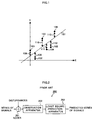
- FIG.1 is a graph showing the principle of the conventional least square method. This FIG.1 shows a case of applying six observation points which have regular intervals to the predicting.
- FIG.1 shows observed values 101 to 106, a predicted result 107, Euclidean distances 108 to 113, that is, margins of errors between predicted result 107 and each observed values.
- predicted result 107 Supposing predicted result 107 and Euclidean distances between observed values 101 to 106 and predicted result 107 as margins of errors 108 to 113, predicted result 107 that will minimize the sum of squares of margins of errors 108 to 113 can be calculated from expressions (1) and (2) below.
- the horizontal axis represents observation points and the vertical axis represents observed values at those observation points.
- “A” represents the gradient of estimation result 107 and "B” represents the intercept.
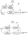
- FIG.2 is a block diagram showing a configuration of a first embodiment of a receiver which utilizes the conventional least square method as linear predicting.
- Receiver 200 shown in FIG.2 is one of examples of general receivers which utilize the conventional least square method to estimate a series of received signals.
- Receiver 200 shown in FIG.2 has observation apparatus 202 and least square prediction apparatus 203.
- Adder 201 which is not included in receiver 200, is described so as to express that received signals are added by disturbances before input into observation apparatus 202.
- a series of signals is input to adder 201, which is supposed to be such a series of signals that can be expressed by a linear expression.
- Least square prediction apparatus 203 estimates a prediction series by minimizing the square of the margin of error based on the aforementioned expressions (1) and (2). This allows a value close to the series of signals to be obtained as the prediction series even if disturbances exist.
- FIG.3 is a block diagram showing a configuration of a second embodiment of a receiver which utilizes the conventional least square method as linear predicting.
- Receiver 300 shown in FIG.3 has antenna 301, frequency offset compensator 302, demodulator 303, frequency offset detector 304 and least square prediction apparatus 305.
- Frequency offset detector 304 detects frequency offsets from received signals.
- Least square prediction apparatus 305 calculates the aforementioned expressions (1) and (2) with the detected frequency offsets to obtain probable frequency offsets, and frequency offset compensator 302 uses this prediction result to compensate received signals. By using the prediction result, demodulator 303 obtains demodulated data of better channel quality with its frequency offset compensated.
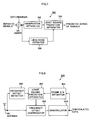
- FIG.4 is a block diagram showing a configuration of a third embodiment of a receiver which utilizes the conventional least square method as linear predicting.
- Receiver 400 shown in FIG.4 is one of examples of receivers in which the conventional least square method referred to FIG.2 is applied to phase estimation essential to detecting synchronization.
- the conventional least square method referred to FIG.2 is applied to phase estimation essential to detecting synchronization.
- This phase rotation can be expressed in a linear expression using time and phase, so the conventional least square method can be applied to compensate those phase rotation.
- Receiver 400 shown in FIG.4 has antenna 401, phase compensator 402, demodulator 403, phase error detector 404, and least square prediction apparatus 405.
- Phase compensator 402 compensates the phase shifts of the received signals based on the prediction result obtained from past received signals and demodulator 403 demodulates those result and obtains demodulated data.
- Phase error detector 404 detects phase shifts based on the received signals of which phase shifts have been compensated by phase compensator 402.
- Least square prediction apparatus 405 calculates the aforementioned expressions (1) and (2) with the detected phase errors to obtain probable frequency offsets, and phase compensator 302 uses this prediction result to compensate received signals. By using the prediction result, demodulator 403 obtains demodulated data of better channel quality with its phase shifts compensated.
- FIG.5 is a block diagram showing a configuration of a fourth embodiment of a receiver which utilizes the conventional least square method as linear predicting.
- Receiver 500 shown in FIG.5 is one of examples of receivers in which the conventional least square method referred to FIG.2 is applied to synchronization shift estimations. Synchronization shifts are originated due to differences in clock oscillation frequencies between transmission and reception.
- the least square method can be applied to the estimation of synchronization shifts because the relationship between the synchronization and the synchronization shifts can be expressed by a linear expression using time.
- Receiver 500 shown in FIG.5 has antenna 501, synchronization timing adjuster 502, demodulator 503, synchronization shift detector 504 and least square prediction apparatus 505.
- Synchronization shift detector 504 detects the synchronization shifts from the received signals between transmission and reception.
- Least square prediction apparatus 505 calculates the aforementioned expressions (1) and (2) with the estimated channel quality, obtains probable synchronization timing, and using this prediction result synchronization shift adjuster 502 corrects the received signals. Using this prediction result, demodulator 503 can obtain high reliability demodulated data with synchronization shifts corrected.
- FIG.6 is a block diagram showing a configuration of a fifth embodiment of a receiver which utilizes the conventional least square method as linear predicting.
- Receiver 600 shown in FIG.6 is one of examples of receivers in which the conventional least square method referred to FIG.2 is applied to channel estimations, presenting an example of diversity combined several reception.
- Diversity combination requires to estimate the coefficients weighted to the received signals from each antenna.
- the least square method can be applied to the estimation of the coefficients for the diversity combining because the quality of the channel can be expressed by a linear expression using time and phase in a short term.
- Receiver 600 shown in FIG.6 has antennas 601 and 602, combiner 603, demodulator 604, channel impulse response estimators 605 and 606, and least square prediction apparatuses 607 and 608.
- Channel impulse response estimator 605 estimates channel impulse responses to signals received by antenna 601.
- Least square prediction apparatus 607 calculates the aforementioned expressions (1) and (2) using the estimated channel quality, obtains probable channel impulse responses and gives this prediction result to combiner 603 and reflects the result in weighting processing on the signal received by antenna 601.
- Channel impulse response estimator 606 estimates channel impulse responses to a signal received by antenna 602.
- Least square prediction apparatus 608 calculates the aforementioned expressions (1) and (2) using the observed values, obtains probable channel impulse responses and gives this prediction result to combiner 603 and reflects the result in weighting processing on the signal received by antenna 602.
- Combiner 603 after the most appropriate coefficients weighted to the signals received by antennas 601 and 602, combines those received signals and obtains high reliability demodulated data through combined diversity.
- the least square method is a method to determine the "gradient" and "intercept,” parameters of a linear expression, that minimizes the Euclidean distance from every observation point, It is capable of predicting best when all the observation points have the same probability, but if the likelihood varies depending on the observation points, it is affected by less likely observed points, deteriorating its prediction accuracy.
- the main point of the present invention is that, it is after weighting every observed value with corresponding likelihood at every observation points that a least square method is utilized as a linear prediction to the observations, in order to improve the accuracy of the linear prediction by making the influence of the probable observed values to the prediction result larger.
- the present invention can improve the accuracy of received signal correction in a receiver, by making a linear prediction more reliable, which is applied for frequency offset compensation, phase shift compensation, synchronization shift adjustment, combined diversity and other signal values estimation.
- a receiver of the present embodiment weights all observed values with corresponding likelihood before utilizing a least square method for linear predicting to the observations.
- FIG.7 is a block diagram showing a configuration of the receiver of Embodiment 1 of the present invention.
- receiver 700 has observation apparatus 702, least square prediction apparatus 703 and likelihood detector 704.
- Adder 701, which is not included in receiver 700, is described so as to express that received signals are added by disturbances before input into observation apparatus 702.
- a series of signals is input to adder 701, which is supposed to be such a series of signals that can be expressed by a linear expression.
- observation apparatus 702. Since the observation result includes disturbances, the observation result contains a certain margin of error even if the series of signals is one that can be expressed by a linear expression.
- Least square prediction apparatus 703 estimates a prediction series by minimizing the square of the margin of error based on the following expressions (3) and (4). This allows a value close to the series of signals to be obtained as the prediction series even if disturbances exist.
- Likelihood detector 704 detects likelihood of received signals and fixes the detected likelihood as a likelihood used by least square prediction apparatus 703.
- the receiver of the present embodiment weights all observed values with corresponding likelihood before utilizing a least square method for linear predicting to the observations, thus the predicted series of signals reflected each probability of the observed values improves the accuracy of linear predicting and eliminates an influence of disturbances.
- a receiver of the present embodiment weights all detected frequency offsets with corresponding frame S/N before utilizing a least square method for linear predicting to the frequency offsets.
- FIG.8 is a block diagram showing a configuration of the receiver of Embodiment 2 of the present invention.
- Receiver 800 shown in FIG.8 has antenna 801, frequency offset compensator 802, demodulator 803, frequency offset detector 804, least square prediction apparatus 805 and frame S/N estimator 806.
- Frequency offset detector 804 detects frequency offsets between transmission and reception from received signals.
- Least square prediction apparatus 805 calculates the aforementioned expressions (3) and (4) with the detected frame S/N to obtain probable frequency offsets, and frequency offset compensator 802 uses this prediction result to compensate received signals. By using the prediction result, demodulator 803 obtains demodulated data of better channel quality with its frequency offset compensated.
- Frame S/N estimator 806 estimates values of frame S/N of received signals and fixes the estimated frame S/N as a likelihood used by least square prediction apparatus 805.
- the receiver of the present embodiment weights all detected frequency offsets with corresponding frame S/N before utilizing a least square method for linear predicting to the detected frequency offsets, thus the predicted series of signals reflected each probability of the detected frequency offsets improves the accuracy of linear predicting and eliminates an influence of disturbances.
- a receiver of the present embodiment weights all detected phase errors with corresponding amplitudes before utilizing a least square method for linear predicting to the phase shifts.
- FIG.9 is a block diagram showing a configuration of the receiver of Embodiment 3 of the present invention.
- Receiver 900 shown in FIG.9 has antenna 901, phase compensator 902, demodulator 903, phase error detector 904, least square prediction apparatus 905 and amplitude calculator 906.
- Phase compensator 902 compensates the phase shifts of the received signals based on the prediction result obtained from past received signals and demodulator 903 demodulates those result and obtains demodulated data.
- Phase error detector 404 detects phase shifts based on the received signals of which phase shifts have been compensated by phase compensator 902.
- Least square prediction apparatus 905 calculates the aforementioned expressions (3) and (4) with the detected amplitudes to obtain probable phase shifts, and phase compensator 902 uses this prediction result to compensate received signals. By using the prediction result, demodulator 903 obtains demodulated data of better channel quality with its phase shifts compensated.
- the receiver of the present embodiment weights all detected phases with corresponding phase errors before utilizing a least square method for linear predicting to the detected phases, thus the predicted series of signals reflected each probability of the detected phases improves the accuracy of linear predicting and eliminates an influence of disturbances.
- a receiver of the present embodiment weights all detected synchronization shifts with corresponding channel quality before utilizing a least square method for linear predicting to the synchronization shifts.
- FIG.10 is a block diagram showing a configuration of the receiver of Embodiment 4 of the present invention.
- Receiver 1000 shown in FIG.10 has antenna 1001, synchronization timing adjuster 1002, demodulator 1003, synchronization shift detector 1004, least square prediction apparatus 1005 and channel quality estimator 1006.
- Synchronization shift detector 1004 detects the synchronization shifts from the received signals between transmission and reception.
- Least square prediction apparatus 1005 calculates the aforementioned expressions (3) and (4) with the estimated channel quality, obtains probable synchronization timing, and using this prediction result synchronization shift adjuster 502 corrects the received signals. Using this prediction result, demodulator 1003 can obtain high reliability demodulated data with synchronization shifts corrected.
- the receiver of the present embodiment weights all detected synchronization shifts with corresponding channel quality before utilizing a least square method for linear predicting to the detected synchronization shifts, thus the predicted series of signals reflected each probability of the detected synchronization shifts improves the accuracy of linear predicting and eliminates an influence of disturbances.
- a receiver of the present embodiment weights all estimated channel impulse responses with corresponding channel quality before utilizing a least square method for linear predicting to the channel impulse responses.
- FIG.11 is a block diagram showing a configuration of the receiver of Embodiment 5 of the present invention.
- Receiver 1100 shown in FIG.11 has antennas 1101 and 1102, combiner 1103, demodulator 1104, channel impulse response estimators 1105 and 1106, least square prediction apparatuses 1107 and 1108 and channel quality estimator 1109.
- Channel impulse response estimator 1105 estimates channel impulse responses to signals received by antenna 1101.
- Least square prediction apparatus 1107 calculates the aforementioned expressions (3) and (4) using the estimated channel quality, obtains probable channel impulse responses and gives this prediction result to combiner 1103 and reflects the result in weighting processing on the signal received by antenna 1101.
- Channel impulse response estimator 1106 estimates channel impulse responses to a signal received by antenna 1102.
- Least square prediction apparatus 1108 calculates the aforementioned expressions (3) and (4) using the estimated channel quality, obtains probable channel impulse responses and gives this prediction result to combiner 1103 and reflects the result in weighting processing on the signal received by antenna 1102.
- Combiner 1103 after the most appropriate coefficients weighted to the signals received by antennas 1101 and 1102, combines those received signals and obtains high reliability demodulated data through combined diversity.
- the receiver of the present embodiment weights all estimated channel impulse responses with corresponding channel quality before utilizing a least square method for linear predicting to the estimated channel impulse responses, thus the predicted series of signals reflected each probability of the estimated channel impulse responses improves the accuracy of linear predicting and eliminates an influence of disturbances.
- the present invention can improve the accuracy of received signal correction in a receiver, by making a linear prediction more reliable, which is applied for frequency offset compensation, phase shift compensation, synchronization shift adjustment, combined diversity and other signal value estimation.
Landscapes
- Engineering & Computer Science (AREA)
- Computer Networks & Wireless Communication (AREA)
- Signal Processing (AREA)
- Power Engineering (AREA)
- Radio Transmission System (AREA)
- Cable Transmission Systems, Equalization Of Radio And Reduction Of Echo (AREA)
- Mobile Radio Communication Systems (AREA)
- Digital Transmission Methods That Use Modulated Carrier Waves (AREA)
Applications Claiming Priority (2)
| Application Number | Priority Date | Filing Date | Title |
|---|---|---|---|
| JP14123198 | 1998-05-22 | ||
| JP14123198A JP3437445B2 (ja) | 1998-05-22 | 1998-05-22 | 線形信号予測を用いた受信装置及び方法 |
Publications (2)
| Publication Number | Publication Date |
|---|---|
| EP0959594A2 true EP0959594A2 (de) | 1999-11-24 |
| EP0959594A3 EP0959594A3 (de) | 2002-11-27 |
Family
ID=15287168
Family Applications (1)
| Application Number | Title | Priority Date | Filing Date |
|---|---|---|---|
| EP99108972A Withdrawn EP0959594A3 (de) | 1998-05-22 | 1999-05-06 | Gewichtete lineare Prädiktion, insbesondere für Trägerrückgewinnung und Kanalschätzung |
Country Status (5)
| Country | Link |
|---|---|
| US (1) | US6404827B1 (de) |
| EP (1) | EP0959594A3 (de) |
| JP (1) | JP3437445B2 (de) |
| KR (1) | KR100335690B1 (de) |
| CN (1) | CN1116753C (de) |
Families Citing this family (21)
| Publication number | Priority date | Publication date | Assignee | Title |
|---|---|---|---|---|
| JP2001111462A (ja) * | 1999-10-06 | 2001-04-20 | Nec Corp | 遅延判定帰還型系列推定ダイバーシティ受信装置 |
| KR100425373B1 (ko) * | 2001-12-05 | 2004-03-30 | 한국과학기술원 | Ls 반송파 주파수오차 추정방법 및 추정기와 그를이용한 송신 다이버시티 시스템 및 3gpp 시스템의송수신기 |
| US7240001B2 (en) * | 2001-12-14 | 2007-07-03 | Microsoft Corporation | Quality improvement techniques in an audio encoder |
| US6934677B2 (en) | 2001-12-14 | 2005-08-23 | Microsoft Corporation | Quantization matrices based on critical band pattern information for digital audio wherein quantization bands differ from critical bands |
| KR100452619B1 (ko) * | 2002-05-15 | 2004-10-13 | 한국과학기술원 | I/q부정합의 추정 및 보상방법과 그 장치, i/q부정합과 dc옵셋의 추정 및 보상방법과 그 장치 |
| KR100453696B1 (ko) * | 2002-05-20 | 2004-10-20 | 전자부품연구원 | 무선 이동 디지털 통신 시스템에서의 개선된 주파수오프셋 추정 방법 |
| US7502743B2 (en) * | 2002-09-04 | 2009-03-10 | Microsoft Corporation | Multi-channel audio encoding and decoding with multi-channel transform selection |
| US7299190B2 (en) * | 2002-09-04 | 2007-11-20 | Microsoft Corporation | Quantization and inverse quantization for audio |
| JP4676140B2 (ja) | 2002-09-04 | 2011-04-27 | マイクロソフト コーポレーション | オーディオの量子化および逆量子化 |
| US7912490B2 (en) * | 2002-11-01 | 2011-03-22 | Interdigital Technology Corporation | Method for channel quality prediction for wireless communication systems |
| US7133457B2 (en) * | 2003-06-27 | 2006-11-07 | Texas Instruments Incorporated | Joint timing recovery for multiple signal channels |
| JP2009501353A (ja) * | 2005-07-14 | 2009-01-15 | コーニンクレッカ フィリップス エレクトロニクス エヌ ヴィ | オーディオ信号合成 |
| US7539612B2 (en) * | 2005-07-15 | 2009-05-26 | Microsoft Corporation | Coding and decoding scale factor information |
| KR100636372B1 (ko) | 2005-11-25 | 2006-10-19 | 한국전자통신연구원 | 위상 오차 추정 장치 및 그를 이용한 위상 오차 보정시스템 |
| CN102047582B (zh) * | 2008-06-20 | 2014-07-30 | 日本电信电话株式会社 | 接收装置、通信系统、以及接收方法 |
| EP2374239B1 (de) * | 2008-12-09 | 2013-02-20 | Telefonaktiebolaget L M Ericsson (PUBL) | Symbol-timing-wiederherstellungstechniken für mehrzweigempfänger |
| CN101959299B (zh) * | 2010-04-02 | 2014-03-12 | 展讯通信(上海)有限公司 | 自动频率控制方法及接收端 |
| CN206503190U (zh) | 2016-09-30 | 2017-09-19 | 林钧琦 | 金属水槽排水无缝接出结构 |
| CN109510791B (zh) * | 2017-09-15 | 2024-10-11 | 华为技术有限公司 | 传输方法和传输装置 |
| CN107966719B (zh) * | 2017-12-22 | 2021-11-19 | 中国交通通信信息中心 | 一种基于信号解码和概率筛选的单星定位增强系统及方法 |
| CN109270503A (zh) * | 2018-07-13 | 2019-01-25 | 中国船舶重工集团公司第七〇九研究所 | 一种频率补偿方法、功率检测装置及雷达系统 |
Family Cites Families (17)
| Publication number | Priority date | Publication date | Assignee | Title |
|---|---|---|---|---|
| US4870579A (en) | 1987-10-01 | 1989-09-26 | Neonics, Inc. | System and method of predicting subjective reactions |
| US5249200A (en) * | 1991-07-30 | 1993-09-28 | Codex Corporation | Device and method for combining precoding with symbol-rate spectral shaping |
| US5295136A (en) | 1992-04-13 | 1994-03-15 | Motorola, Inc. | Method of performing convergence in a, least mean square, adaptive filter, echo canceller |
| US5432821A (en) * | 1992-12-02 | 1995-07-11 | University Of Southern California | System and method for estimating data sequences in digital transmissions |
| JP3560991B2 (ja) | 1993-09-20 | 2004-09-02 | 株式会社東芝 | 適応型最尤系列推定装置 |
| WO1995017052A1 (en) | 1993-12-15 | 1995-06-22 | Ntt Mobile Communications Network Inc. | Adaptive equalizer |
| JP3180240B2 (ja) | 1993-12-27 | 2001-06-25 | 日本電信電話株式会社 | 適応等化器 |
| CA2162571C (en) * | 1994-05-07 | 2001-03-13 | Toshiro Kawahara | Echo canceler and method for learning for the same |
| JPH07336278A (ja) | 1994-06-06 | 1995-12-22 | Oki Electric Ind Co Ltd | 伝搬路推定器 |
| JPH088786A (ja) | 1994-06-16 | 1996-01-12 | Matsushita Electric Ind Co Ltd | 適応等化器 |
| JP3109710B2 (ja) | 1994-10-28 | 2000-11-20 | 株式会社エヌ・ティ・ティ・ドコモ | 予測形同期検波器 |
| US5546430A (en) * | 1995-05-01 | 1996-08-13 | Universite du Quebeca Hull | Detector for demodulating a received signal and producing an information data signal with reduced intersymbol interference |
| JP3256646B2 (ja) | 1995-06-05 | 2002-02-12 | 株式会社エヌ・ティ・ティ・ドコモ | 適応干渉キャンセル受信機 |
| US5677951A (en) | 1995-06-19 | 1997-10-14 | Lucent Technologies Inc. | Adaptive filter and method for implementing echo cancellation |
| JP3024524B2 (ja) * | 1995-09-25 | 2000-03-21 | 日本電気株式会社 | キャリア同期ユニット及び同期方法 |
| US5790596A (en) | 1996-03-15 | 1998-08-04 | Motorola, Inc. | Radiotelephone communication unit displaying chronological information |
| JPH09294095A (ja) | 1996-04-26 | 1997-11-11 | Oki Electric Ind Co Ltd | 適応等化器 |
-
1998
- 1998-05-22 JP JP14123198A patent/JP3437445B2/ja not_active Expired - Fee Related
-
1999
- 1999-05-06 EP EP99108972A patent/EP0959594A3/de not_active Withdrawn
- 1999-05-19 US US09/313,990 patent/US6404827B1/en not_active Expired - Fee Related
- 1999-05-19 KR KR1019990017961A patent/KR100335690B1/ko not_active Expired - Fee Related
- 1999-05-21 CN CN99107025A patent/CN1116753C/zh not_active Expired - Fee Related
Also Published As
| Publication number | Publication date |
|---|---|
| JP3437445B2 (ja) | 2003-08-18 |
| EP0959594A3 (de) | 2002-11-27 |
| KR100335690B1 (ko) | 2002-05-08 |
| KR19990088381A (ko) | 1999-12-27 |
| US6404827B1 (en) | 2002-06-11 |
| JPH11340883A (ja) | 1999-12-10 |
| CN1116753C (zh) | 2003-07-30 |
| CN1237054A (zh) | 1999-12-01 |
Similar Documents
| Publication | Publication Date | Title |
|---|---|---|
| US6404827B1 (en) | Method and apparatus for linear predicting | |
| US6940932B2 (en) | Diversity receiver | |
| KR100457987B1 (ko) | 심볼처리가향상된전송시스템및수신기 | |
| US7313086B2 (en) | OFDM receiver, semiconductor integrated circuit and OFDM method for receiving a signal | |
| US6219334B1 (en) | Receiving apparatus for receiving orthogonal frequency division multiplexing signal and receiving method thereof | |
| US7436906B2 (en) | Synchronous detector with high accuracy in detecting synchronization and a method therefor | |
| EP0854588A2 (de) | Leistungsregelung und Trägersynchronisierung in einem zellularen Mobil-Telefonsystem | |
| US20120201221A1 (en) | Wireless communication apparatus | |
| US8862065B2 (en) | Apparatus and method for frequency offset estimation in mobile communication system | |
| US8867570B2 (en) | Methods of transmitting pilot tones and data in spatial multiplexing transmission | |
| US8243858B2 (en) | Receiver and method for receiving | |
| US20100290356A1 (en) | Wimax communication system and method | |
| US6748026B1 (en) | Distortion estimation apparatus, frequency offset compensation apparatus and reception apparatus | |
| US7043680B2 (en) | Frequency division multiplex transmission signal receiving apparatus using a plurality of carriers | |
| US6970686B2 (en) | Diversity system and diversity method | |
| EP1047232A2 (de) | Verfahren zur Kanalschätzung | |
| EP0958666B1 (de) | Kompensation der dopplerverschiebung in einem mobilkommunikationssystem | |
| US6381290B1 (en) | Mobile unit for pilot symbol assisted wireless system and method of improving performance thereof | |
| US7925286B2 (en) | Method, a program and a module to estimate a doppler maximum frequency and an oscillator frequency offset, receiver including the module | |
| US20020136189A1 (en) | Radio communication system and apparatus | |
| EP1381173B1 (de) | Drahtlose Kommunikationsvorrichtung zur Empfangsrichtungserkennung | |
| EP2709329A1 (de) | Differentielle demodulationsvorrichtung und differentielles demodulationsverfahren | |
| JP2003332952A (ja) | 線形信号予測を用いた受信装置及び方法 | |
| JPWO2006093331A1 (ja) | 移動無線通信装置、及びチャネル推定値演算方法 | |
| US8787504B2 (en) | Enhancing channel estimates made in digital communications receivers |
Legal Events
| Date | Code | Title | Description |
|---|---|---|---|
| PUAI | Public reference made under article 153(3) epc to a published international application that has entered the european phase |
Free format text: ORIGINAL CODE: 0009012 |
|
| AK | Designated contracting states |
Kind code of ref document: A2 Designated state(s): AT BE CH CY DE DK ES FI FR GB GR IE IT LI LU MC NL PT SE |
|
| AX | Request for extension of the european patent |
Free format text: AL;LT;LV;MK;RO;SI |
|
| PUAL | Search report despatched |
Free format text: ORIGINAL CODE: 0009013 |
|
| AK | Designated contracting states |
Kind code of ref document: A3 Designated state(s): AT BE CH CY DE DK ES FI FR GB GR IE IT LI LU MC NL PT SE |
|
| AX | Request for extension of the european patent |
Free format text: AL;LT;LV;MK;RO;SI |
|
| RIC1 | Information provided on ipc code assigned before grant |
Free format text: 7H 04L 25/02 A, 7H 04L 27/227 B, 7H 04L 27/00 B |
|
| 17P | Request for examination filed |
Effective date: 20030103 |
|
| 17Q | First examination report despatched |
Effective date: 20030305 |
|
| AKX | Designation fees paid |
Designated state(s): DE ES FR GB IT SE |
|
| STAA | Information on the status of an ep patent application or granted ep patent |
Free format text: STATUS: THE APPLICATION IS DEEMED TO BE WITHDRAWN |
|
| 18D | Application deemed to be withdrawn |
Effective date: 20050111 |