EP0959408A2 - Acquisition d'information de configuration d'appareil pendant le démarrage d'un appareil de traitement d'information - Google Patents
Acquisition d'information de configuration d'appareil pendant le démarrage d'un appareil de traitement d'information Download PDFInfo
- Publication number
- EP0959408A2 EP0959408A2 EP99303905A EP99303905A EP0959408A2 EP 0959408 A2 EP0959408 A2 EP 0959408A2 EP 99303905 A EP99303905 A EP 99303905A EP 99303905 A EP99303905 A EP 99303905A EP 0959408 A2 EP0959408 A2 EP 0959408A2
- Authority
- EP
- European Patent Office
- Prior art keywords
- open
- information
- configuration
- housing
- configuration information
- Prior art date
- Legal status (The legal status is an assumption and is not a legal conclusion. Google has not performed a legal analysis and makes no representation as to the accuracy of the status listed.)
- Withdrawn
Links
Images


Classifications
-
- G—PHYSICS
- G06—COMPUTING OR CALCULATING; COUNTING
- G06F—ELECTRIC DIGITAL DATA PROCESSING
- G06F11/00—Error detection; Error correction; Monitoring
- G06F11/22—Detection or location of defective computer hardware by testing during standby operation or during idle time, e.g. start-up testing
- G06F11/2289—Detection or location of defective computer hardware by testing during standby operation or during idle time, e.g. start-up testing by configuration test
Definitions
- the present invention generally relates to a method of, an information processing device for, and a control circuit for obtaining device information as well as a computer-readable memory medium having a program recorded therein for performing the method of obtaining device information.
- the present invention particularly relates to a method of, an information processing device for, and a control circuit for obtaining information on a system configuration regarding connected peripherals as well as a computer-readable memory medium having a program embodied therein for performing the method of obtaining information on a system configuration regarding connected peripherals
- Fig.1 is an illustrative drawing showing an exemplary appearance of a related-art personal computer.
- a personal computer 1 includes a computer 2, a keyboard 3, a mouse 4, and a display 5.
- Fig.2 is a flowchart of an exemplary startup procedure of a related-art personal computer.
- BIOS basic input output system
- the BIOS accesses a ROM which is built in a device connected to IDE, a PCI bus, and a SCSI bus, and obtains device-configuration information regarding this device stored in the ROM. Then, the BIOS stores the device-configuration information "ATA3 IDENTIFY DEVICE" in a non-volatile RAM (step S1-3). After this, other processes which are part of the startup procedure are performed before the procedure ends (step S1-4).
- the device-configuration information obtained by the BIOS includes setting information such as a memory volume, a type of an access mode, etc., if the pertinent device is a hard drive, for example. This information is used for displaying of a used memory volume, access control, etc.
- the device-configuration information There are two different ways to obtain the device-configuration information. One is a manual mode and, the other is an automatic mode. In the manual mode, device-configuration information is input by manual operation. The device-configuration information is then stored in a non-volatile RAM.
- device-configuration information is obtained automatically from a memory of the device.
- the device-configuration information obtained in an automatic manner is stored in a system RAM.
- the information stored in the system RAM is also stored in a non-volatile RAM in order to insure consistency of the device-configuration information.
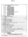
- Figs.3, 4, and 5 are illustrative drawings for explaining related-art device-configuration information obtained by a BIOS.
- the device-configuration information obtained by the BIOS includes 0-255 words shown in Figs.3 through 5.
- the contents of Figs.3 through 5 are shown in INFORMATION TECHNOLOGY AT Attachment-3 (ATA-3) Interface, 26. Oct. 1995, P.61-70, which is available at a T13 forum on Internet FTP://fission.dt.wdc.com/.
- the device-configuration information includes "General configuration bit-significant information" information in the O-th word, "Number of logical cylinders” information in the first word, “Number of logical heads” information in the third word, “Number of logical sectors per logical track” information in the sixth word, “Serial number” information in the tenth through nineteenth words, “Number of Vendor specific bytes” information in the twenty second word, “Firmware revision” information in the twenty third through twenty sixth words, "Model number” information in the twenty seventh through forty sixth words, “Capabilities” information in the forty ninth word, "PIO data transfer cycle timing mode” information in the fifty first word, “Number of current logical cylinders” information in the fifty fourth word, “Number of current logical heads” information in the fifty fifth word, “Number of current logical sectors per track” information the fifty sixth word, “Current capacity in sectors” information in the fifty seventh and fifty eighth words, "Total number of
- Numberer of logical cylinders information in the first word indicates the number of logical cylinders available to a user in a default translation mode.
- Numberer of logical heads information in the third word shows the number of logical heads with respect to logical cylinders available to a user in the default translation mode.
- Numberer of logical sectors per logical track information in the sixth word indicates the number of logical sectors with respect to logical tracks available to a user in the default translation mode.
- Serial number information in the tenth through nineteenth words represents a serial number of the device.
- Numberer of Vendor specific bytes information in the twenty second word indicates the number of bits which is specific to a vendor, and is allocated to the device.
- Model number information in the twenty seventh through forty sixth words represents a model number of the device.
- Capabilities information in the forty ninth word is an indication of a device capacity. For example, information indicative of whether a standby timer function is supported is stored in this word.
- PIO data transfer cycle timing mode information in the fifty first word is used for storing a transfer timing of a PIO (programmed input/output).
- Number of current logical cylinders information in the fifty fourth word indicates the number of logical cylinders in a current translation mode.
- Number of current logical heads information in the fifty fifth word represents the number of logical heads with respect to logical cylinders in the current translation mode.
- Number of current logical sectors per track information in the fifty sixth word signifies the number of logical sectors with respect to logical tracks in the current translation mode.
- Total number of user addressable sectors information in the sixtieth and sixty first words shows the total number of sectors available to the user.
- Multiword DMA transfer mode active information in the sixty third word indicates a valid/invalid status of the multi-word-DMA-transfer mode.
- Minimum multiword DMA transfer cycle time per word information in the sixty fifth word represents a minimum cycle time per word in the multi-word-DMA-transfer mode.
- Manufacturer's recommended multiword DMA cycle time information in the sixty sixth word specifies a cycle time recommended by a manufacturer during the multi-word-DRAM-transfer mode.
- Minimum PIO transfer cycle time without flow control information in the sixty seventh word indicates a minimum cycle time during a PIO transfer other than during a time period of flow control.
- Minimum PIO transfer cycle time with IORDY flow control indicates a minimum cycle time during the PIO transfer at the time of flow control.
- device-configuration information is obtained regardless of an actual change to a system configuration each time the BIOS operates at such times as during a power-on operation, an OS-restart operation, a personal-computer-reset operation. This is done in order to make sure that the device-configuration information is reliably obtained when a system configuration is changed during a power off of the computer. Because of the need for such an operation, a whole series of a startup procedure becomes undesirably lengthy.
- a method of obtaining device-configuration information includes the steps of a) detecting whether a case of a device is open, and b) obtaining device-configuration information regarding devices connected to the device when the step a) indicates that the case has been open.
- the device configuration has been changed when there is an indication that the case has been open, and, then, the device-configuration information is obtained. If the situation tells that there is no need to obtain the device-configuration information, no action is taken, thereby reducing a startup time of the device.
- the method as described above further includes a step of keeping in storage an open/closed status of the case detected by the step of detecting, wherein the step b) obtains the device-configuration information when the open/closed status of the case indicates that the case has been open.
- the device-configuration information is obtained based on a record of the past indicative of whether the case has been open.
- the device-configuration information is thus obtained when the case has ever been open.
- the method as described above is such that the step b) obtains the device-configuration information according to the open/closed status of the case when a device-information-acquirement flag is set to valid, and obtains the device-configuration information regardless of the open/closed status of the case when the device-information-acquirement flag is set to invalid.
- One is an operation in which the device-configuration information is obtained according to the open/closed status of the case which has been recorded, and the other is an operation in which the device-configuration information is obtained regardless of the open/closed status of the case.
- the method as described above is such that the step b) is performed at a time when the device is switched on or when a startup program of the device is executed.
- a startup procedure including obtaining the device-configuration information is simplified where the startup procedure is performed when a startup program is executed or when power is turned on in the device.
- a startup of the device can be quickly made.
- the objects presented earlier can also be achieved by a device having an information processing unit which operates based on device-configuration information obtained with regard to devices connected thereto.
- the device includes a case which houses the information processing unit, a case-open/closed-detection unit which detects whether the case is open, and a device-configuration-information obtaining unit which obtains device-configuration information regarding devices connected to the information processing unit when the case-open/closed-detection unit indicates that the case has been open.
- the device configuration has been changed when there is an indication that the case has been open, and, then, the device-configuration information is obtained. If the situation tells that there is no need to obtain the device-configuration information, no action is taken, thereby reducing a startup time of the device.
- the device as described above further includes a detection-result storing unit which keeps in storage a detection result obtained by the case-open/closed-detection unit, and supplies the detection result to the device-configuration-information obtaining unit.
- the device-configuration information is obtained based on a record of the past indicative of whether the case has been open.
- the device-configuration information is thus obtained when the case has ever been open.
- the device as described above further includes a setting unit which is set either to a valid status or to an invalid status, wherein if the setting unit holds the valid status, the device-configuration-information obtaining unit obtains the device-configuration information when the case-open/closed-detection unit indicates that the case has been open, whereas if the setting unit holds the invalid status, the device-configuration-information obtaining unit obtains the device-configuration information regardless of the detection result obtained by the case-open/closed-detection unit.
- the possibility that the device configuration has been changed is assessed based on whether the case has been open, and the device-configuration information is obtained only when there is a possibility that the device configuration has been changed.
- a process of obtaining the device-configuration information is not performed, thereby shortening a startup time of the device.
- the device as described above is such that the device-configuration-information obtaining unit obtains the device-configuration information at a time when the information processing unit is switched on or when a startup program of the information processing unit is executed.
- a startup procedure including obtaining the device-configuration information is simplified where the startup procedure is performed when a startup program is executed or when power is turned on in the device.
- a startup of the device can be quickly made.
- control circuit having an information processing unit which operates based on device-configuration information obtained with regard to devices connected thereto and having a case which houses the information processing unit.
- the control circuit includes a device-configuration-information obtaining unit which obtains device-configuration information regarding devices connected to the information processing unit when it is detected that the case has been open.
- the device configuration has been changed when there is an indication that the case has been open, and, then, the device-configuration information is obtained. If the situation tells that there is no need to obtain the device-configuration information, no action is taken, thereby reducing a startup time of the device.
- control circuit as described above further includes a detection unit which detects whether the case is open, wherein the device-configuration-information obtaining unit obtains the device-configuration information when the detection unit indicates that the case has been open.
- the device configuration has been changed when there is an indication that the case has been open, and, then, the device-configuration information is obtained. If the situation tells that there is no need to obtain the device-configuration information, no action is taken, thereby reducing a startup time of the device.
- control circuit as described above further includes a setting unit which is set either to a valid status or to an invalid status, wherein if the setting unit holds the valid status, the device-configuration-information obtaining unit obtains the device-configuration information when the detection unit indicates that the case has been open, whereas if the setting unit holds the invalid status, the device-configuration-information obtaining unit obtains the device-configuration information regardless of a detection result obtained by the detection unit.
- One is an operation in which the device-configuration information is obtained according to a detection result obtained by the detection unit, and the other is an operation in which the device-configuration information is obtained regardless of the detection result.
- control circuit as described above is such that the device-configuration-information obtaining unit obtains the device-configuration information at a time when the information processing unit is switched on or when a startup program of the information processing unit is executed.
- a startup procedure including obtaining the device-configuration information is simplified where the startup procedure is performed when a startup program is executed or when power is turned on in the device.
- a startup of the device can be quickly made.
- the objects presented earlier can also be achieved by a computer-readable memory medium having a program therein for causing a computer to obtain device-configuration information.
- the program includes a case-open/closed-detection unit configured to detect whether a case of the computer is open, and a device-configuration-information obtaining unit configured to obtain device-configuration information regarding devices connected to the computer when the case-open/closed-detection unit indicates that the case has been open.
- the computer-readable memory medium as described above is such that the device-configuration-information obtaining unit obtains the device-configuration information according to a detection result obtained by the case-open/closed-detection unit when a device-information-acquirement flag is set to valid, and obtains the device-configuration information regardless of the detection result when the device-information-acquirement flag is set to invalid.
- One is an operation in which the device-configuration information is obtained according to the detection result obtained by the case-open/closed-detection unit, and the other is an operation in which the device-configuration information is obtained regardless of the detection result.
- the computer-readable memory medium as described above is such that the program is a startup program of the computer.
- a startup procedure including obtaining the device-configuration information is simplified where the startup procedure is performed when a startup program is executed or when power is turned on in the device.
- a startup of the device can be quickly made.
- Fig.6 is an illustrative drawing showing a configuration of a personal computer according to a first embodiment of the present invention.
- the same elements as those of Fig.1 are referred to by the same numerals, and a description thereof will be omitted.
- a personal computer 100 of this embodiment differs from the personal computer 1 in a configuration of a computer 101 and a procedure of a startup program.
- the personal computer 100 includes the keyboard 3, the mouse 4, the display 5, and the computer 101.
- the keyboard 3, the mouse 4, and the display 5 are connected to the computer 101.
- the keyboard 3 and the mouse 4 are used for supplying instructions and data to the computer 101.
- the display 5 is used for displaying results of processing performed by the computer 101.
- the computer 101 performs a startup program at the time of power on, an OS restart, and a reset, and obtains device-configuration information on built-in devices such as a hard drive, a floppy-disk drive, a CD-ROM drive, and various extension boards. After the startup operation, the computer 101 attends to processing such as data transfer based on the device-configuration information obtained during the startup operation.
- Fig.7 is an isometric view of the computer according to the first embodiment of the present invention.
- the computer 101 includes a frame 102, a front panel 103, and a cover 104, all of which together make up a case. Inside the case, the computer 101 includes a power supply 105, a mother board 106, a riser card 107, a built-in hard drive 108, a built-in floppy-disk drive 109, a built-in-CD-ROM drive 110, a built-in card 111, and a cover-open/closed-detection switch 112.
- the frame 102 has the cover 104 attached thereto via screws 113, so that an opening is closed by the cover 104.
- On the frame 102 are fixedly mounted the mother board 106, the riser card 107, the built-in hard drive 108, the built-in floppy-disk drive 109, and the built-in-CD-ROM drive 110.
- the front panel 103 is fixed to the front of the frame 102.
- the front panel 103 has a power switch 113, a floppy-disk-insertion opening 114 for the built-in floppy-disk drive 109, and a disk-tray-ejection unit 115 for the built-in-CD-ROM drive 110.
- the cover 104 has a U shape, and covers the sides and the top of the frame 102.
- the power supply 105 is provided near the back of the frame 102.
- a power cord (not shown) is connected to the power supply 105 to supply utility power thereto.
- the power supply 105 regulates supplied utility power, and provides power for each part of the computer.
- the mother board 106 is provided in parallel to the bottom surface of the frame 102.
- the mother board 106 has a processor 116, a memory 117, a riser-card connector 118, etc., mounted thereon.
- the riser card 107 is connected to the riser-card connector 118 mounted on the mother board 106, and is situated in parallel to the side of the frame 102.
- the riser card 107 has the cover-open/closed-detection switch 112, a PCI-bus connector 119, and an ISA-bus connector 120 mounted thereon.
- the PCI-bus connector 119 and the ISA-bus connector 120 are connected to the built-in card 111, which is provided in parallel to the frame 102.
- the built-in card 111 is connected to the frame 102 via the riser card 107.
- the cover-open/closed-detection switch 112 is fixedly mounted at a top end of the riser card 107, such that the cover-open/closed-detection switch 112 is operated according to whether the cover 104 is open or closed.
- the cover-open/closed-detection switch 112 is switched on when the cover 104 is open, and is switched off when the cover 104 is closed, for example.
- An on/off status of the cover-open/closed-detection switch 112 indicates an open/closed status of the cover 104.
- the detection result of the cover-open/closed-detection switch 112 is supplied to the frame 102 via the riser card 107.
- Fig.8 is a block diagram of the computer according to the first embodiment of the present invention.
- the computer 101 mainly includes the mother board 106, the riser card 107, the built-in hard drive 108, the built-in floppy-disk drive 109, and the built-in-CD-ROM drive 110.
- the mother board 106 includes the microprocessor 116, the memory (system RAM) 117, bridge circuits 121 and 122, a ROM 123, a sensor chip 124, a PCI bus 125, an ISA bus 126, an IDE bus 127, and a non-volatile RAM 137.
- the processor 116 performs processes according to programs loaded in the system RAM 117.
- the bridge circuit 121 is situated between the processor 116, the memory 117, and the PCI bus 125 so as to attend to control of data transfer therebetween.
- the bridge circuit 122 is situated at an intersection between the PCI bus 125, the ISA bus 126, the IDE bus 127, the ROM 123, and the sensor chip 124.
- the bridge circuit 122 attends to control of data transfer between the PCI bus 125, the ISA bus 126, the IDE bus 127, the ROM 123, and the sensor chip 124.
- the system RAM 117 is comprised of DRAMs or the like, and is used as a work area by the microprocessor 116.
- the ROM 123 stores therein a BIOS (basic input output system) serving as a startup program.
- BIOS basic input output system
- the startup program stored in the ROM 123 is loaded to the system RAM 117 when power of the power supply 105 is turned on by operating the power switch 113. Also, the startup program is loaded when a restart instruction is issued by the OS operating on the computer 101 or when a reset operation is performed on the keyboard 3. The startup program loaded to the system RAM 117 is then executed.
- the startup program obtains device-configuration information regarding devices connected to the PCI bus 125, the ISA bus 126, or the IDE bus 127.
- the startup program then stores the obtained device-configuration information in the non-volatile RAM 137.
- the sensor chip 124 receives various sensor signals for monitoring purposes.
- the sensor chip 124 is connected to the riser card 107, and supplies a detection result to the mother board 106 when the detection result indicative of an open/closed status of the cover 104 is obtained by the cover-open/closed-detection switch 112.
- the sensor chip 124 has a RAM 124a built therein.
- the riser card 107 includes the PCI-bus connector 119, the ISA-bus connector 120, the cover-open/closed-detection switch 112, and a cover-open/closed-status latching circuit 128.
- the PCI-bus connector 119 is connected to the PCI bus 125, and receives the built-in card 111 therein when the built-in card 111 is PCI-bus compatible.
- the ISA-bus connector 120 is connected to the ISA bus 126, and receives the built-in card 111 when the built-in card 111 is ISA-bus compatible.
- a built-in-type hard drive is connected to a hard-drive-extension-placement unit 130, and is also connected to IDE-connection cable and a power cable.
- the sensor chip 124 is comprised of a commercially available sensor chip IC.
- LM80 manufactured by National Semiconductor may be used as the sensor chip 124.
- the sensor chip LM80 detects a plurality of sensor signals, and supplies them to he bridge circuit 122.
- the RAM 124a provided in the sensor chip 124 is used for setting a flag therein as an indication of what is detected.
- the sensor chip 124 receives power from a battery BATT, so that the contents of the RAM 124a are maintained even when power is turned off.
- the cover-open/closed-detection switch 112 is situated at the top end of the riser card 107.
- the cover-open/closed-detection switch 112 is turned on when the cover 104 is open, and is turned off when the cover 104 is closed.
- the cover-open/closed-detection switch 112 is connected to the sensor chip 124 via the cover-open/closed-status latching circuit 128.
- the cover-open/closed-status latching circuit 128 is driven by the battery BATT, and keeps operating even when the power switch 113 is turned off.
- the cover-open/closed-status latching circuit 128 holds therein an open/closed status obtained by the cover-open/closed-detection switch 112.
- the contents of the cover-open/closed-status latching circuit 128 are purged when a reset is instructed. When this happens, the contents of the cover-open/closed-status latching circuit 128 become invalid.
- the cover-open/closed-detection switch 112 is switched off, i.e., when the cover 104 is open, the contents become valid.
- the non-volatile RAM 137 stores the device-configuration information obtained by the BIOS at the time of a device startup.
- Fig.9 is a flowchart of the startup program of the personal computer according to the first embodiment of the present invention.
- the power switch is turned on by a user (step S2-1).
- the OS operating on the computer 101 issues a restart instruction, or a reset operation is performed on the keyboard 3.
- the BIOS starts operating (step S2-2).
- the BIOS is capable of operating in one of two different modes.
- the first mode is used when the BIOS obtains the device-configuration information based on a check on the cover-open/closed-status latching circuit 128, and the second mode is used when the BIOS makes an access to peripheral devices under any circumstances to obtain the device-configuration information.
- Switching between the first mode and the second mode is made at the time of BIOS operation by checking a cover-open/closed-detection-switch flag F of the RAM 124a provided in the sensor chip 124.
- the cover-open/closed-detection-switch flag F is set to either a valid status or an invalid status by a process performed in advance.
- the BIOS accesses the RAM 124a to check the status of the cover-open/closed-detection-switch flag F (step S2-3).
- step S2-3 If the cover-open/closed-detection-switch flag F is found to be invalid at the step S2-3, i.e., if the second mode is selected, a process of obtaining device-configuration information is performed regardless of whether the cover 104 has been opened, so that the device-configuration information (ATA-3 IDENTIFY DEVICE) is acquired from all the connected devices as described in connection with Figs.3 through 6.
- the device-configuration information is then stored in the non-volatile RAM 137 (step S2-4). After the device-configuration information is obtained and stored in the non-volatile RAM 137 at the step S2-4, other processes of the startup procedure are performed (step S2-5).
- cover-open/closed-detection-switch flag F is found to be valid at the step S2-3, i.e., if the first mode is selected, a check is made by accessing the cover-open/closed-status latching circuit 128 so as to determine whether the cover 104 has been opened (step S2-6).
- step S2-6 finds that the cover-open/closed-status latching circuit 128 is valid so as to indicate the open status of the cover, it is ascertained that the cover 104 was open before the power is on with an aim of adding, taking out, or replacing a device such as a hard-drive, a card, or the like.
- device-configuration information (ATA-3 IDENTIFY DEVICE) is obtained from all the devices connected to the PCI bus 125, the ISA bus 126, and the IDE bus 127 at the step S2-4.
- step S2-6 finds that the cover-open/closed-status latching circuit 128 holds an off status indicative of that the cover 104 has not been opened, it is ascertained that a change in a peripheral-device configuration such as adding, taking out, or replacing a hard-drive, a card, or the like has not been made. Accordingly, the startup program BIOS proceeds to perform other processes, and sets the computer to an initial state thereof (step S2-5).
- cover-open/closed-status latching circuit 128 After the cover-open/closed-status latching circuit 128 is accessed at the step S2-6, it is reset (steps S2-7, S2-8). Because of this reset operation, the cover-open/closed-status latching circuit 128 can latch a new status next time the cover is opened.
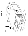
- Fig.10 is an illustrative drawing for explaining how to take out (open) the cover from the computer according to the first embodiment of the present invention.
- the cover 104 When there is a need to add, remove, or replace a device with respect to the computer 101, the cover 104 is removed.
- the screws 113 are taken out from the back of the computer 101 as shown in Fig.10.
- the cover 104 is slide toward the back as shown by arrows A. This sliding movement should fee the front end of the cover 104 from an engagement with the front panel 103, and, also, free the bottom ends of the cover 104 from an engagement with the frame 102. Then, the cover 104 is moved in a direction shown by arrows B to complete a removal operation.
- Fig.11 is an illustrative drawing for explaining how to add a device to the computer according to the first embodiment of the present invention.
- the hard-drive extension 129 When a hard-drive extension 129 is to be installed, the hard-drive extension 129 is connected to an IDE-connection cable 132 extending from the mother board 106, and is also connected to a power cable 133 extending from the power supply 105. Then, the hard-drive extension 129 is mounted on the hard-drive-extension-placement unit 130, and is fixed by means of screws 131.
- a built-in extension card 134 is inserted into either the PCI-bus connector 119 or the ISA-bus connector 120, whichever is available and compatible with a pertinent bus type, provided on the riser card 107.
- the built-in extension card 134 may be an SCSI card. Such an SCSI card may be connected to an external hard drive 136 via an SCSI cable 135.
- the cover 104 In order to install the hard-drive extension 129 and/or the built-in extension card 134 in the computer 101, the cover 104 needs to be removed as shown in Fig.10 and Fig.11. When the cover 104 is removed, the cover-open/closed-detection switch 112 is turned off, so that the cover-open/closed-status latching circuit 128 holds a status indicative of removal of the cover 104, i.e., holds a valid status.
- Fig.9 The procedure of Fig.9 is performed when the power switch 113 is turned on after the cover 104 is closed subsequent to installing the hard-drive extension 129 and/or the built-in extension card 134 in the computer 101. This is the case even when the power switch 113 is tuned on while the cover 104 is open.
- the cover-open/closed-status latching circuit 128 Since the cover-open/closed-status latching circuit 128 holds a valid status indicative of the fact that the cover 104 has been opened, a check of the valid status of the cover-open/closed-status latching circuit 128 at the step S2-6 leads to the operation of the step S2-4 for obtaining the device-configuration information (ATA-3 IDENTIFY DEVICE) regarding all the devices connected to the PCI bus 125, the ISA bus 126, or the IDE bus 127.
- the information latched by the cover-open/closed-status latching circuit 128 is reset after it is accessed. Because of the reset operation, the cover-open/closed-status latching circuit 128 can be set to a valid status when the cover 104 is opened next time.
- the startup operation is simplified, and is shorter when the user switches on the power switch 113 or either when the OS operating on the computer 101 issues a restart instruction or when a reset operation is performed on the keyboard 3 of the personal computer 100.
- the cover-open/closed-status latching circuit 128 is provided for the purpose of holding the detection result obtained by the cover-open/closed-detection switch 112, so that the device-configuration information is obtained based on whether the cover 104 has been opened as well as whether the cover 104 is being open.
- the present invention is not limited to this configuration, and the device-configuration information may be obtained only based on whether the cover 104 is being open.
- the first embodiment has been described mainly with reference to a case in which devices are added to the existing configuration. Since the device-configuration information is obtained based on whether the cover 104 has been opened, however, this embodiment is equally applicable to cases where devices are removed or replaced as long as such operation is conducted by opening the cover 104.
- Fig.12 is a block diagram of a computer according to a second embodiment of the present invention.
- the same elements as those of Fig.8 are referred to by the same numerals, and a description thereof will be omitted.
- a computer 200 of the second embodiment differs from the computer 101 of Fig.8 in that the cover-open/closed-detection switch 112 is connected to the sensor chip 124 without the cover-open/closed-status latching circuit 128 intervening therebetween. In the second embodiment, therefore, the detection result indicates that the cover 104 is open only when the power switch 113 is turned on while the cover 104 is being open.
- Fig.13 is a flowchart showing a procedure of a startup program according to the second embodiment of the present invention.
- the power switch 113 is turned on by a user (step S3-1).
- the OS operating on the computer 101 issues a restart instruction, or a reset operation is performed on the keyboard 3.
- the BIOS starts operating (step S3-2).
- the BIOS is capable of operating in one of two different modes.
- the first mode is used when the BIOS obtains the device-configuration information based on the status of the cover-open/closed-detection switch 112, and the second mode is used when the BIOS makes an access to peripheral devices under any circumstances to obtain the device-configuration information.
- Switching between the first mode and the second mode is made at the time of BIOS operation by checking the cover-open/closed-detection-switch flag F of the RAM 124a provided in the sensor chip 124.
- the cover-open/closed-detection-switch flag F is set to either a valid status or an invalid status by a process performed in advance.
- the BIOS accesses the RAM 124a to check the status of the cover-open/closed-detection-switch flag F (step S3-3).
- step S3-3 If the cover-open/closed-detection-switch flag F is found to be invalid at the step S3-3, a process of obtaining device-configuration information is performed regardless of whether the cover 104 is open, so that the device-configuration information (ATA-3 IDENTIFY DEVICE) is acquired from all the connected devices as described in connection with Figs.3 through 6.
- the device-configuration information is then stored in the non-volatile RAM 137 (step S3-4). After the device-configuration information is obtained and stored in the non-volatile RAM 137 at the step S3-4, other processes of the startup procedure are performed (step S3-5).
- cover-open/closed-detection-switch flag F is found to be valid at the step S3-3, a status of the cover-open/closed-detection switch 112 is checked by using the sensor chip 124 so as to determine whether the cover 104 is open (step S3-6).
- step S3-6 finds that the cover 104 is open, it is ascertained that a device such as a hard-drive extension or a card is added, removed, or replaced.
- device-configuration information (ATA-3 IDENTIFY DEVICE) is obtained from all the devices connected to the PCI bus 125, the ISA bus 126, and the IDE bus 127 (step S3-4).
- the startup program BIOS proceeds to perform other processes to set the computer to an initial state thereof (step S3-5).
- step S3-6 finds that the result obtained from the cover-open/closed-detection switch 112 via the sensor chip 124 indicates that the cover 104 is not open, it is ascertained that a change in a device configuration such as adding, taking out, or replacing a hard-drive, a card, or the like has not been made. Without obtaining the device-configuration information (ATA-3 IDENTIFY DEVICE) from devices connected to the PCI bus 125, the ISA bus 126, or the IDE bus 127, the procedure goes to the step S3-5, where other processes are performed.
- ATA-3 IDENTIFY DEVICE ATA-3 IDENTIFY DEVICE
Landscapes
- Engineering & Computer Science (AREA)
- General Engineering & Computer Science (AREA)
- Theoretical Computer Science (AREA)
- Computer Hardware Design (AREA)
- Quality & Reliability (AREA)
- Physics & Mathematics (AREA)
- General Physics & Mathematics (AREA)
- Stored Programmes (AREA)
Applications Claiming Priority (2)
| Application Number | Priority Date | Filing Date | Title |
|---|---|---|---|
| JP15537398A JP3573960B2 (ja) | 1998-05-20 | 1998-05-20 | 機器情報取得方法及び情報処理装置、制御回路並びに機器情報取得方法を実行するプログラムを記憶したコンピュータで読み取り可能な記憶媒体 |
| JP15537398 | 1998-05-20 |
Publications (2)
| Publication Number | Publication Date |
|---|---|
| EP0959408A2 true EP0959408A2 (fr) | 1999-11-24 |
| EP0959408A3 EP0959408A3 (fr) | 2000-08-09 |
Family
ID=15604525
Family Applications (1)
| Application Number | Title | Priority Date | Filing Date |
|---|---|---|---|
| EP99303905A Withdrawn EP0959408A3 (fr) | 1998-05-20 | 1999-05-19 | Acquisition d'information de configuration d'appareil pendant le démarrage d'un appareil de traitement d'information |
Country Status (2)
| Country | Link |
|---|---|
| EP (1) | EP0959408A3 (fr) |
| JP (1) | JP3573960B2 (fr) |
Cited By (2)
| Publication number | Priority date | Publication date | Assignee | Title |
|---|---|---|---|---|
| FR2825879A1 (fr) * | 2001-06-07 | 2002-12-13 | Dell Products Lp | Systeme et procede pour afficher une information de l'etat d'un systeme d'ordinateur |
| US7653897B2 (en) * | 2003-07-21 | 2010-01-26 | Autodesk, Inc. | Displaying user operation data |
Families Citing this family (2)
| Publication number | Priority date | Publication date | Assignee | Title |
|---|---|---|---|---|
| JP4647248B2 (ja) * | 2004-06-09 | 2011-03-09 | 富士通株式会社 | 保守部品管理プログラムおよび保守部品管理装置 |
| JP2009211170A (ja) * | 2008-02-29 | 2009-09-17 | Toshiba Corp | 情報処理装置および起動制御方法 |
Family Cites Families (1)
| Publication number | Priority date | Publication date | Assignee | Title |
|---|---|---|---|---|
| US5634137A (en) * | 1995-01-17 | 1997-05-27 | International Business Machines Corporation | Method and apparatus for updating system configuration based on open/closed state of computer housing cover |
-
1998
- 1998-05-20 JP JP15537398A patent/JP3573960B2/ja not_active Expired - Fee Related
-
1999
- 1999-05-19 EP EP99303905A patent/EP0959408A3/fr not_active Withdrawn
Cited By (2)
| Publication number | Priority date | Publication date | Assignee | Title |
|---|---|---|---|---|
| FR2825879A1 (fr) * | 2001-06-07 | 2002-12-13 | Dell Products Lp | Systeme et procede pour afficher une information de l'etat d'un systeme d'ordinateur |
| US7653897B2 (en) * | 2003-07-21 | 2010-01-26 | Autodesk, Inc. | Displaying user operation data |
Also Published As
| Publication number | Publication date |
|---|---|
| EP0959408A3 (fr) | 2000-08-09 |
| JPH11328094A (ja) | 1999-11-30 |
| JP3573960B2 (ja) | 2004-10-06 |
Similar Documents
| Publication | Publication Date | Title |
|---|---|---|
| US5471674A (en) | Computer system with plug-in override of system ROM | |
| KR100190736B1 (ko) | 컴퓨터 시스템 | |
| US5987536A (en) | Computer system having flash memory bios which can be accessed while protected mode operating system is running | |
| KR950007109B1 (ko) | 휴대형 컴퓨터 | |
| JP5681689B2 (ja) | 省電力状態からの復帰時間を短縮する方法およびコンピュータ | |
| US20070043889A1 (en) | Information processing apparatus and access method | |
| KR100816763B1 (ko) | 플래시 메모리 모듈을 주기억장치로 사용하는 전자 시스템및 그것의 부팅 방법 | |
| EP3889735A1 (fr) | Appareil de traitement d'informations et procédé de commande | |
| JP4886846B2 (ja) | 情報処理装置および不揮発性半導体メモリドライブ | |
| US20090228640A1 (en) | Information processing apparatus and non-volatile semiconductor memory drive | |
| US20100268863A1 (en) | Information processing apparatus | |
| US20090228641A1 (en) | Information processing apparatus and non-volatile semiconductor memory drive | |
| US20050223209A1 (en) | Apparatus for fast booting computer and method for the same | |
| US8364930B2 (en) | Information processing apparatus and storage drive adapted to perform fault analysis by maintenance of tracing information | |
| EP0959408A2 (fr) | Acquisition d'information de configuration d'appareil pendant le démarrage d'un appareil de traitement d'information | |
| US7640425B2 (en) | Disk apparatus and electronic apparatus | |
| US20070233995A1 (en) | Information processing apparatus and memory address space allocation method | |
| US20090228762A1 (en) | Inforamtion Precessing Apparatus and Non-Volatile Semiconductor Memory Drive | |
| US20210397231A1 (en) | Temperature control device, information processing apparatus, and temperature control method | |
| JP2006259903A (ja) | 情報処理装置および起動方法 | |
| US20090222614A1 (en) | Information processing apparatus and nonvolatile semiconductor memory drive | |
| KR100568246B1 (ko) | 컴퓨터 시스템 및 그 제어방법 | |
| US20070118717A1 (en) | Information processing apparatus and memory address space assignment method | |
| WO2009110141A1 (fr) | Appareil de traitement d'informations et lecteur de mémoire à semi-conducteurs non volatile | |
| JP5085493B2 (ja) | 情報処理装置及びそのブート制御方法 |
Legal Events
| Date | Code | Title | Description |
|---|---|---|---|
| PUAI | Public reference made under article 153(3) epc to a published international application that has entered the european phase |
Free format text: ORIGINAL CODE: 0009012 |
|
| AK | Designated contracting states |
Kind code of ref document: A2 Designated state(s): AT BE CH CY DE DK ES FI FR GB GR IE IT LI LU MC NL PT SE |
|
| AX | Request for extension of the european patent |
Free format text: AL;LT;LV;MK;RO;SI |
|
| PUAL | Search report despatched |
Free format text: ORIGINAL CODE: 0009013 |
|
| AK | Designated contracting states |
Kind code of ref document: A3 Designated state(s): AT BE CH CY DE DK ES FI FR GB GR IE IT LI LU MC NL PT SE |
|
| AX | Request for extension of the european patent |
Free format text: AL;LT;LV;MK;RO;SI |
|
| AKX | Designation fees paid | ||
| STAA | Information on the status of an ep patent application or granted ep patent |
Free format text: STATUS: THE APPLICATION IS DEEMED TO BE WITHDRAWN |
|
| 18D | Application deemed to be withdrawn |
Effective date: 20010210 |
|
| REG | Reference to a national code |
Ref country code: DE Ref legal event code: 8566 |